1
User Manual - GA-P135-024
5
Page 6
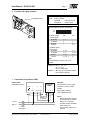
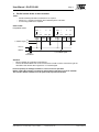
Wiring configuration
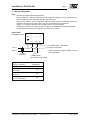
Notes:
• Actuators are provided with color coded wires.
• Observe polarity on secondary of transformers. All common and signal (-) must be connected in line.
Incorrect polarity can cause controller damage or operation error.
• Long wire runs requires a 4-wire configuration (connect common for power and control signal at the
actuator or close by). Greater than a 0.2 V drop must be avoided for any common wire.
• Always use a separate transformer when controller power is full-wave rectified.
• Controller and actuators must have separate transformers for paralleled multi-actuator application.
• Provide overload protection for line voltage and disconnect as required.
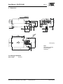
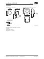
GA-P135-024
Proportional control
com
+
Y
U
~
blk
red
wht grn
(+) U, Feedback signal*, (0)2-10 VDC
(-) or supply of 10/15 VDC
Line L2
Volts L1
24 VAC
Transformer
Multiple actuators
(maximum quantities)
(-) (+)
* Signal can provide position indication or masterslave applications.
Y, Control signal
(0)2-10 VDC, or (0)4-20 mA
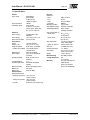
GA-P135-024
Proportional
Stacking (torque is additive)
4
Parallel connection
(0)2-10 VDC
20
Parallel connection
(0)4-20 mA
10
Master-slave
via U, feedback signal
10
Phone (858) 578-7887 & (888) GO INTEC
Fax (858) 578-4633 & (888) FX INTEC
INTEC Controls, Inc., P.O. Box 12506, La Jolla, CA 92039
www.inteccontrols.com
Specification subject to change without notice
Printed in Germany