1
Document TypeError! Reference source not found.
EDMS ID Number Error! Reference source not found.
Date
9 Nov. 2012
1. INTRODUTION
The ESS Linac will include in total about 20 Beam Current Monitors (BCMs). These devices
are primarily used to measure the beam current and charge, but they will also provide input
for the MPS (Machine Protection System) and may also be used for the synchronization of
the target wheel to the beam arrival time [1].
It is planned to install most of the BCMs in the low energy end of the Linac (i.e. from the
source to the DTL) where there are fewer BLMs (Beam Loss Monitors). In addition to the
absolute current measurement, these BCMs will be used to measure the differential beam
current (i.e. current difference between two subsequent BCMs) and act on the BIS (Beam
Interlock System) if beam losses exceed certain thresholds.
It is planned to use commercial ACCTs (AC Current Transformers) for most of the BCMs.
These devices can be used to measure the pulse profile with a measurement rise/fall time of
a few hundred ns. In addition to the ACCTs, it is planned to use a few FCTs (Fast Current
Transformers) wherever shorter response times are required. The FCT has a bandwidth in
the order of a few GHz and can be used, for example, to measure the performance of the
MEBT (Medium Energy Beam Transport) choppers with a very short pulse rise/fall time.
2. ACCT OPERATING PRINCIPLE
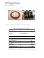
The ACCT is basically a high permeability toroid core with about 10-100 winding turns. The
ACCT is mounted on the beam pipe at a location where the beam current has to be
measured. The beam goes through the ACCT and generates a voltage across the windings
(similar to a one-turn primary winding). This voltage basically has the same profile as the
beam pulse, but it does not include the very fast beam variations due to its limited
bandwidth. For example, one cannot normally see the individual bunches, but just the
envelope of the beam current. Also, there will be a droop of a few % per ms during the
pulse flat top. This is because the ACCT lower cut-off frequency normally goes down to a
few Hz but does not include 0 Hz. Therefore the ACCT cannot measure DC currents.
The output voltage of the ACCT is then transferred by some cables to the analogue ACCT
electronics, where the signal is filtered and conditioned. This electronics is normally supplied
by the toroid manufacturer and it is installed out of tunnel to minimize the risk of damage
due to excessive radiation from the beam. The output signal of the electronics can then be
seen on an oscilloscope or a voltmeter (in case of CW beams).
At ESS, it is planned to integrate the BCMs into the ICS (Integrated Control System).
Therefore, the analogue signal from the ACCT electronics has to be digitized, processed and
sent to the user interface via the control network as described in the following sections.
3