1
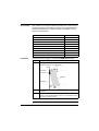
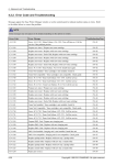
0RGLFRQ
)DFWRU\&DVW+0,
1:0
,QVWUXFWLRQ6KHHW
31004691 04 Version 1.0
)DFWRU\&DVW+0,1:0,QVWUXFWLRQ6KHHW
5HDG0H)LUVW
Before you can use your 1:0module, you must configure
it with an Internet Protocol (IP) address. Configure your module by
using either one of the two following methods.
z
z
Create a new user-configured IP address
Use the derived default address
Note: Operating on a Corporate Network
Before placing the 140 NWM 100 00 on a corporate network,
Schneider Electric recommends that you discuss the installation with
your MIS department.
3DWHQW
5HJLVWUDWLRQ
Quantum Automation Series equipment is protected by U.S. Patent
number 5,302,136 and by European Patent number 93202982.0The NWM is protected by U.S. Patent numbers 4897777, 4992926,
4969083, 5131092, 5151978, 5159673, 5245704, 5251302, 5805442,
5975737, 5982362, 6061603, 6151625, 6285454.
Other patents pending.
8VHU
&RQILJXUHG,3
$GGUHVV
A user-configured IP address requires you to assign the IP address.
Therefore, if a new IP address must be assigned, obtain it from your
system administrator. Assign the new IP address using your Concept
Programming Panel.
Record the IP network address on the space located on the front panel
of the module behind the door.
For more information refer to the latest version of the Concept for
Quantum User Manual (840USE42800).
31004691 03 September 2003
1
'HULYHG
'HIDXOW,3
$GGUHVV
If you choose not to assign the module an IP address from a DHCP or
BOOTP server, you may connect the module using its default IP
Address, which is derived from its Mac address. To do this proceed as
follows.
1. Locate the global address label on
the front panel of the module.
2. Note the right most eight digits.
3. Convert the digits from hexadecimal
to decimal. Each pair of hexadecimal
numbers will result in a decimal
number between 0 and 255. This is the
default IP address.
,(((*/2%$/$''5(66
0000540B72A8
5 4 0 B 7 2 A 8
84.11.114.168
The hexadecimal conversion can be done with a scientific calculator or
a computer-based calculator program.
Record the IP network address on the writable label located on the
front panel of the module.
2WKHU7RROV
BootP Lite and the EthCfg tool (included in Concept).
IRU,3$GGUHVV
$VVLJQPHQW
$&KDQQHO
'HYLFHV
The 140 NWM 100 00 module is capable of communicating over either:
z
z
10 Base-T or 100 Base -T network
100 Base-FX Ethernet network at any given time, but not both networks at
the same time.
Note: Do not attempt to connect module directly to another
device.The cable for each device must be routed through an Ethernet
hub switch for the network to function properly.
2
31004691 03 September 2003
,OOXVWUDWLRQ
This illustration depicts the 140 NWM 100 00.
Model Number
Module Description
Color Code
1:0
)DFWRU\&DVW+0,
$FWLYH
5HDG\
)DXOW
5XQ
&ROO
/LQN
LED Display
7[$FW
5[$FW
0%
Removable Door
0%)GXSOH[
.HUQHO$SSO
WRITE ASSIGNED IP ADDRESS ABOVE
Do Not Duplicate Address
Use Permanent Felt-tip Pen
IP Address
Area
Global Address Label
100 Base Fx
MT-RJ Cable Connector
%DVH
)[
10/100 Base-T
RJ-45 Cable Connector
31004691 03 September 2003
7
3
Module
Specification
Table
Key specifications for the Quantum 140 NWM100 00 module are:
z
z
Communication
Ports
One auto-sensing 10/100Base-T shielded twisted pair (RJ-45 connector) port
One 100Base-FX (MT-RJ connector) port
Both ports work in the same way but only one at a time.
LED Indicators
Label
Color
Description
Active
Green
Indicates that the backplane is operating.
Ready
Green
Indicates that the module is healthy.
Fault
Red
Indicates when the NWM is in a crash state.
Run
Green
Flashes to indicate diagnostic code, as described in the Run
LED Status table below.
Coll
Red
Flashes when Ethernet collisions occur.
Link
Green
On when Ethernet link is active.
TxAct
Green
Flashes to indicate Ethernet transmission.
RxAct
Green
Flashes to indicate Ethernet reception.
Kernel
Amber
On when in Kernel mode.
Flashing while in download mode.
10MB
Green
On when the module is connected to a 10 Megabit network.
100MB
Green
On when the module is connected to a 100 Megabit
network.
Fduplex
Green
On when Ethernet is operating in the full duplex mode.
Appl
Green
On when crash log entry exists.
Bus Current
Required
900 mA
Power
Dissipation
4.5 W
Fuse
None
Programming Software
Type and Version
Concept, Ver. 2.6 with SR2. Please also see the “Concept V2.6 Configuration for
NWM 100 00 Module” section of this document.
Firmware
NOE Upgradable
4
Field upgradable via FTP or Programming Panel.
31004691 03 September 2003
Run LED
Status
The state of the Run LED indicator is either steady or flashing. Thus, the
Run LED indicator provides diagnostic information. The following table
lists each available state of the Run LED indicator:
Indicator State
Status
On (steady)
Normal operation: The NWM module is ready for network communication.
Number of Flashes in sequence
One
Not used
Two
Not used
Three
No Link: The network cable is not connected or is defective.
Four
Duplicate IP address
Five
No IP address: The module is attempting to obtain an IP address from a
BOOTP server.
Six
Using default IP address
Seven
No valid executive NWM present
Eight
Invalid IP configuration (Likely cause: Default gateway is not on the same
subnet mask as the module.)
Nine
Flash file system is corrupted
FactoryCast
Web Server
This module contains an enhanced embedded Web server, called the
FactoryCast Web server, which you may customize.
This Web server allows the following browser functions.
z
z
z
z
z
z
z
z
Display controller’s configuration, real time register values, and
personality
Display Ethernet statistics for the node
Display status, configuration, and register values of any remote /
distributed I/O
Create and view graphic real time templates using Java beans
Create and view real time templates in spreadsheet format
Create custom Web pages
Use Concept symbols or direct addresses
Use SNMP with private MIB
Note: The embedded Web site must be viewed using Internet
Explorer, Version 4.0 with SP2 (or higher).
Once the module has been installed, these pages can be viewed across
the World Wide Web. Obtain the IP address or URL from you system
administrator. Then type the address into your browser.
For more information on the FactoryCast Web server, obtain a copy of
the latest version of the FactoryCast User’s Guide (31001229) from
your distributor or local sales office.
31004691 03 September 2003
5
Key Features
Installation
This module is a FactoryCast HMI that provides a PLC with access to
an Ethernet network. The module can plug into any available slot in a
Quantum backplane and is capable of being hot swapped. The key
features are listed below.
Feature
140 NWM 100 00
HTTP Server
yes
SNMP V2 Agent
yes
Flash File System
yes
FTP Server
yes
Modbus Messaging
yes
Schneider Private MIB
yes
FactoryCast Application
yes
User Programmable Webpages
yes
Java Virtual Machine
yes
Perform the following steps to install a 140 NWM 100 00 module..
Step
Action
1
Holding the module at an angle, mount it on to the two hooks
located near the top of the backplane.
Hook
Backplane
Connector
Module
Backplane
6
2
Swing the module down so its connector engages the backplane
connector.
3
Using a Phillips head screw driver, tighten the screw at the
bottom of the module between 2 and 4 in-lbs. or between .22 and
.45 Newton meters of torque.
31004691 03 September 2003
Concept V2.6
Configuration
for
NWM 100 00
Module
As the first step of configuring this module, you need to use the
ModConnect tool once. This tool is supplied with Concept V2.6 and will
install the supplied NWM 100.mdc file. This process will import the
140 NWM 100 00 module into the Concept moduledatabase and will
copy the associated help file (NWM100.hlp) into the Concept directory.
Additional
Information
For complete information concerning the 140 NWM 100 00 modules,
please obtain a copy of the FactoryCast HMI User Guide from your
distributor or local sales office. A copy of this manual can also be
obtained from the Schneider Electric web site.
31004691 03 September 2003
7
31004691 04
04
Visit http://www.schneider-electric.com for your nearest Schneider Electric affiliate.
Printed in
8‘
September 2003
31004691 04 Septiembre 2003