1
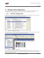
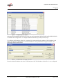
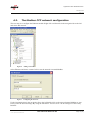
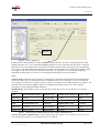
Application Note ModbusTCP.doc
SCM-7032-025
Rev 1.03
How to configure an Anybus Modbus-TCP
slave module with Unity Pro L
Saved: 2008-03-05
Filename: Application Note ModbusTCP.doc
HMS Industrial Networks AB
Page 1 (25)
Application Note ModbusTCP.doc
SCM-7032-025
Rev 1.03
Document history
Revision
1.00
Date
2007-06-20
Description
Created
Author
Thorbjörn Palm
1.01
2007-07-18
Minor revision
Thorbjörn Palm
1.02
2007-07-20
Minor correction
Thorbjörn Palm
1.03
2008-03-05
Updated layout
Thorbjörn Palm
More information about the network and products
The latest manuals and EDS-files can be found on the HMS homepage, www.anybus.com
The Modbus user organisation has a homepage on the Internet, http://www.modbus.org/. Several technical
guides are available in or via this page.
Saved: 2008-03-05
Filename: Application Note ModbusTCP.doc
HMS Industrial Networks AB
Page 2 (25)
Application Note ModbusTCP.doc
SCM-7032-025
Rev 1.03
Contents
1.
Applicable Anybus products ...................................................................................................................4
2.
Requirements ............................................................................................................................................4
3.
Solution overview .....................................................................................................................................5
4.
Modbus TCP configuration.....................................................................................................................6
4.1.
The PLC configuration .....................................................................................................................6
4.2.
The Modbus-TCP network configuration .........................................................................................8
4.3.
The PLC program ...........................................................................................................................12
5.
Anybus configuration.............................................................................................................................16
5.1.
IP settings........................................................................................................................................16
5.2.
I/O configuration.............................................................................................................................17
5.3.
Communicator configuration ..........................................................................................................18
5.4.
X-gateway configuration ................................................................................................................20
6.
Testing .....................................................................................................................................................22
Appendix .........................................................................................................................................................24
Modbus-TCP addresses................................................................................................................................24
Saved: 2008-03-05
Filename: Application Note ModbusTCP.doc
HMS Industrial Networks AB
Page 3 (25)
Application Note ModbusTCP.doc
SCM-7032-025
Rev 1.03
1.
Applicable Anybus products
Description
Name / Type
Anybus X-gateway
Modbus-TCP
Anybus Communicator
Modbus-TCP
Anybus-Slave
Modbus-TCP
Anybus-PCI
Modbus-TCP
Anybus-CompactCom
Modbus-TCP
Anybus-IC
EtherNet/IP (supporting Modbus-TCP)
Note: The configuration of the X-gateway and the Anybus Communicator is described in this document. In
the case with the remaining Anybus products this document is applicable, but the configuration is depending
on the type of application.
2.
Requirements
Description
Name / Type
Version
Schneider Premium PLC
TSX P571634 with ETY Port master
Modbus-TCP card
n.a.
PLC software
Unity Pro L
2.1
Anybus IPconfig tool
Anybus IPconfig
1.3.1.1
X-gateway Network Interface Addendum
Anybus X-gateway Ethernet Slave
Interface, Network Interface
Addendum
1.02
X-gateway User Manual
X-gateway Generic User Manual
1.02
Communicator User Manual
Anybus Communicator for Ethernet,
User Manual
2.01
Slave Field bus Appendix
Anybus-S Ethernet, Field bus
Appendix
1.42
IC Field bus Appendix
Anybus-IC Ethernet/IP, Field bus
Appendix
1.52
PCI Interface Design Guide
Anybus-S Slave & Master, Parallel
Interface Design Guide
2.0
CompactCom Network Interface Appendix
CompactCom Modbus-TCP, Network
Interface Appendix
2.02
Power supply 24VDC
n.a.
n.a
Configuration cables
n.a.
n.a.
Null modem cable (Supplied with the
Anybus X-gateway)
n.a.
n.a.
Saved: 2008-03-05
Filename: Application Note ModbusTCP.doc
HMS Industrial Networks AB
Page 4 (25)
Application Note ModbusTCP.doc
SCM-7032-025
Rev 1.03
3.
Solution overview
This application note describes how to configure an Anybus Modbus-TCP Slave product with a Schneider
PLC. Below you can find an overview of the system described in this document. Other nodes may be
attached to the network, but are not necessary
Note: This document is valid for all Anybus Modbus TCP products, however sections written in italics
describe the configuration of a specific product.
The contents describe step by step how a configuration is done. This document assumes the reader is familiar
with industrial communication, Modbus-TCP networks and HMS Communicator and X-gateway.
PLC
PLC
Master
Master
Modbus-TCP
Modbus-TCP
Modbus Slave
Anybus Communicator
Example of
Serial Network
Modbus-TCP
Slave
Anybus X-gateway
Other network
i.e. Ethernet
Ethernet
PC
Client
Figure 1
Hardware connection overview.
Saved: 2008-03-05
Filename: Application Note ModbusTCP.doc
HMS Industrial Networks AB
Page 5 (25)
Application Note ModbusTCP.doc
SCM-7032-025
Rev 1.03
4.
Modbus TCP configuration
To configure the PLC and the Modbus network the tool Unity Pro L is used. Firstly the PLC needs to be
configured and secondly the Modbus network. Start the program and follow the steps below.
4.1.
The PLC configuration
Start the Unity Pro L program and open the file menu and select new. In the window seen below, select the
relevant PLC from the list, in this case the TSX P571634 model.
Figure 2
Configuring the type of PLC.
Press OK and the PLC with predefined modules is configured. Double click on the X-bus in the navigation
list to the left and the window seen below will appear in a new window.
Figure 3
Configuring the PLC modules.
Double click on the modules 2, 3 etcetera for configuring additional modules. In this case two discrete I/O
modules are used, one for input and one for output data. After double clicking on one of the extra modules
the list seen below will be shown.
Saved: 2008-03-05
Filename: Application Note ModbusTCP.doc
HMS Industrial Networks AB
Page 6 (25)
Application Note ModbusTCP.doc
SCM-7032-025
Rev 1.03
Figure 4
Configuring the I/O modules.
Select the desired module and click OK. In this case the I/O modules TSX DEY16D2 AND TSX DSY16T2
are added to the configuration. To configure additional modules repeat the previous steps.
To configure the IP settings of the PLC, open the PLC menu and select Set Address. The IP address is the
address to which the configuration is to be downloaded to if using TCP/IP for the project transfer. The
following window will be visible.
Figure 5
Configuring the IP settings of the PLC.
Enter the desired IP address and select TCPIP and press OK. The IP address for the PLC is now configured.
Saved: 2008-03-05
Filename: Application Note ModbusTCP.doc
HMS Industrial Networks AB
Page 7 (25)
Application Note ModbusTCP.doc
SCM-7032-025
Rev 1.03
4.2.
The Modbus-TCP network configuration
The next step is to configure the Ethernet module. Right click on Networks in the navigation list to the left
and select add network.
Figure 6
Adding a network.
Select Ethernet and choose a name. In this case the network is named Modbus.
Figure 7
Configuring the network.
Under Communication in the navigation list to the left double click on the network named Modbus as seen
below. Enter the desired settings. By using the alternative “From a server” the IP settings are retrieved by
BOOTP.
Saved: 2008-03-05
Filename: Application Note ModbusTCP.doc
HMS Industrial Networks AB
Page 8 (25)
Application Note ModbusTCP.doc
SCM-7032-025
Rev 1.03
BOOTP
Figure 8
The IP configuration.
Enable the I/O scanning tab by selecting YES in the module utilities. The I/O scanning function uses the
Modbus function 0x17, 23dec, Read/Write Multiple Registers to access the data from the nodes. Using this
function the user can configure data and transfer it between network nodes without specific programming.
To be able to scan both Input and Output data the Anybus module needs to be configured for Anybus mode.
The registers and coils can also be accessed in other ways, by commands. In each case the mapping is
depending on what mode is selected. For a more detailed description see the note below.
Note:
Anybus mode: When the Anybus product is configured for Anybus mode both the Input and Output data
can be accessed by the I/O scanning function. In Anybus mode it is also possible to access coils with the
same memory location as of a register. In other words it is possible to access individual bits of a register. See
the table below showing the Modbus addresses in Modbus and Anybus mode. For a more detailed
description see the Appendix Modbus addresses.
Modbus mode: If the Modbus mode is used only the Output data can be accessed by the I/O scanning
function.
Data
Anybus mode, Register
Register type
Modbus mode, Register
Register type
Input data
1-1024
Input/Holding
1-1024
Input
Output data
1025-2048
Input/Holding
1-1024
Holding
Data
Anybus mode, Coil
Coil type
Modbus mode, Coil
Coil type
Input coil
1-16384
Input/Output
1-16384
Input
Output coil
16385-32768
Input/Output
1-16384
Output
Figure 9
Table showing the Modbus addresses used in Anybus and Modbus mode.
Note for the Anybus Communicator: In the Communicator the registers 257 to 1024 are reserved. For a
more detailed description see the Communicator User Manual.
Saved: 2008-03-05
Filename: Application Note ModbusTCP.doc
HMS Industrial Networks AB
Page 9 (25)
Application Note ModbusTCP.doc
SCM-7032-025
Rev 1.03
Note for the Anybus CompactCom: Also note the Anybus and Modbus mode is not supported by the Anybus
CompactCom. The module has a complete different I/O configuration and the maximum data exchange is
256 bytes in each direction refer to the CompactCom Software Design Guide.
Then open the I/O scanning tile as shown below.
Figure 10 Configuring the I/O scanning.
In this case the PLC is reading the Slave index 0 and writing to the index 1024 using the “zero notation”. In
the PLC the words with address 0 and 10 are used. The repetitive rate can be set to less than 500 ms as used
in this example.
The next step is to double click on the Ethernet module and configure the network the PLC module is to be
connected to. In this case the network named Modbus previously configured is selected. Open the
configuration in the left navigation list and double click on the Ethernet module as seen below. Select the
desired network and close the tile.
Saved: 2008-03-05
Filename: Application Note ModbusTCP.doc
HMS Industrial Networks AB
Page 10 (25)
Application Note ModbusTCP.doc
SCM-7032-025
Rev 1.03
Figure 11 Configuring the PLC Ethernet module.
Saved: 2008-03-05
Filename: Application Note ModbusTCP.doc
HMS Industrial Networks AB
Page 11 (25)
Application Note ModbusTCP.doc
SCM-7032-025
Rev 1.03
4.3.
The PLC program
To test the communication between the slave and the master PLC a simple PLC program is used. The first
step is to define the variables. Open the elementary variables and add the variables as seen below.
Figure 12 Defining the variables.
The second step is to put together a PLC program. The program is depending on the application; in this case
a test program is used. Insert a new task of the FAST type and add a new section to the section folder. This is
done by right clicking the Tasks folder under the Program folder and select add new task. Then right click on
sections to add the program.
Figure 13 Adding a new program.
The program is built in the ladder language and named test in this case.
An ADD-function, ADD_INT, is used in this case. The easiest way to insert the function is to use the
Function Input Assistant.
Saved: 2008-03-05
Filename: Application Note ModbusTCP.doc
HMS Industrial Networks AB
Page 12 (25)
Application Note ModbusTCP.doc
SCM-7032-025
Rev 1.03
Function Input Asisstent
Figure 14 Adding the ADD function.
Click on the Function Input Assistant button and then on the browse button to the right in the row called FFB
type.
Browse button
Figure 15 Browsing the Function library.
Double click on the Libset as seen below to expand the library. Select the ADD_INT function and press OK.
Then click with the mouse on the working space to the right.
Saved: 2008-03-05
Filename: Application Note ModbusTCP.doc
HMS Industrial Networks AB
Page 13 (25)
Application Note ModbusTCP.doc
SCM-7032-025
Rev 1.03
Figure 16 Inserting the ADD function.
The start condition is controlled by the Boolean named Start. To insert the start condition mark the EN
connector and click on the normally open contact button, the button is found in the top left corner. See the
window below.
The next step is to connect the defined variables to the ADD function. Double click on the respective
connector and select the variables as seen in the picture below. The Out variable is connected to the IN1
connector and the constant to the IN2 connector. The Out variable is also connected to the OUT connector.
Figure 17 Configuring the ADD function.
The next step is to insert a new animation table to monitor the variables. Right click on the Animation Tables
in the navigation list to the left and select add a new Animation Table. Double click in the name column and
add the desired variables.
Saved: 2008-03-05
Filename: Application Note ModbusTCP.doc
HMS Industrial Networks AB
Page 14 (25)
Application Note ModbusTCP.doc
SCM-7032-025
Rev 1.03
Figure 18 The animation table.
To be able to monitor the variables the program needs to be transferred to the PLC. Firstly the project needs
to be compiled and saved. Press the rebuild all button and then save the project. After that open the PLC
menu and select Transfer project to the PLC. Press the transfer button.
Figure 19 Downloading the program.
Saved: 2008-03-05
Filename: Application Note ModbusTCP.doc
HMS Industrial Networks AB
Page 15 (25)
Application Note ModbusTCP.doc
SCM-7032-025
Rev 1.03
5.
Anybus configuration
5.1.
IP settings
Make sure each node on the network has a unique IP address. The IP settings of the Anybus Modbus-TCP
modules can be configured in various ways. It is recommended to use the Anybus IPconfig tool for
configuring the IP-settings. The Anybus IPconfig tool can be used to configure the IP settings of all Anybus
Modbus-TCP modules. The program can be downloaded at HMS 1 website. Start the program and the main
window will be opened.
Figure 20 The Anybus IPconfig tool.
The program scans the network for Anybus Ethernet modules. By double clicking on the desired module the
IP-settings can be entered. The settings can be configured manually or the DHCP function can be used.
DHCP is activated by default.
Figure 21 Configuring the IP settings.
1
www.anybus.com
Saved: 2008-03-05
Filename: Application Note ModbusTCP.doc
HMS Industrial Networks AB
Page 16 (25)
Application Note ModbusTCP.doc
SCM-7032-025
Rev 1.03
As mentioned before there are other ways to configure the IP settings. See the notes below for more
information.
Note for the Anybus-S Slave, and Communicator:
DIP switches 1-8 set the last part of the IP address, 192.168.0.xxx. The switches will be found next to the
indication LEDs on the Communicator and the Slave Interface. The modules can also be configured by
mailbox commands or by the ethcfg.cfg configuration file.
Note for the X-gateway:
The X-gateway can be configured by the DIP switches as described above or by the ethcfg.cfg configuration
file.
Note for the Anybus PCI card:
The module can be configured by mailbox commands or by the ethcfg.cfg configuration file.
Note for the Anybus-IC:
For the Anybus–IC for Modbus-TCP the configuration is depending on the application. The IP address is set
by the IP configuration parameters if the NA-bit is 1 or, if mounted, by switches if the NA-bit is 0. The IP
address can also be configured by the network via EtherNet/IP via the TCP/IP Interface Object.
Note for the Anybus CompactCom:
The Anybus CompactCom can be configured by the network configuration object
For further instructions see the respective manual or appendix.
5.2.
I/O configuration
The Anybus product has to be configured for the same I/O sizes as set up in the Modbus scanner
configuration. The configuration procedure is depending on the type of module. See the notes below.
Note: The I/O sizes are depending on the application, the configured I/O sizes in this chapter are just
examples.
Note for the Anybus-S Slave Interface and the Anybus PCI card:
The Anybus Slave Interface and the Anybus PCI card are configured by mailbox commands. Refer to the
respective Fieldbus Appendix for details.
Note for the Anybus CompactCom and the Anybus-IC:
The Anybus CompactCom and the Anybus-IC are configured by messages send by the application. Refer to
the respective Design Appendix for details.
Note for the Anybus Communicator and the Anybus X-gateway:
The configuration of the Anybus Communicator and the Anybus X-gateway is described in separate sections
below.
Saved: 2008-03-05
Filename: Application Note ModbusTCP.doc
HMS Industrial Networks AB
Page 17 (25)
Application Note ModbusTCP.doc
SCM-7032-025
Rev 1.03
5.3.
Communicator configuration
To configure the Communicator start the ABC Config Tool and start a new project. Select the field bus
Modbus-TCP and the desired I/O data size.
Figure 22 Configuring the Field bus.
In this case 8 bytes are configured and the Modbus addressing mode is disabled. This means that the Anybus
mode is enabled, see the chapter 4.2 and the Communicator User Manual.
In this case a loop back dongle at the serial connection of the Communicator is connected. To loop data the
generic data mode is selected; all other values are left at their defaults.
Figure 23 Configuring the Communicator.
The next step is to configure the sub-network.
Saved: 2008-03-05
Filename: Application Note ModbusTCP.doc
HMS Industrial Networks AB
Page 18 (25)
Application Note ModbusTCP.doc
SCM-7032-025
Rev 1.03
Figure 24 Configuring the sub network.
Right click on new node and add a consume and a produce transaction as shown above. Change the Offline
timeout time to 200 ms and leave the settings for the produce transaction at the defaults. Right click on the
produce and consume transaction respectively and select add data. In this case 8 bytes of data is used.
Note: The update time for the produce transaction is to be set to less than the offline timeout time for the
consume transaction; in this case the update time is set to 100 ms.
For a more detailed description see the Communicator user manual.
Saved: 2008-03-05
Filename: Application Note ModbusTCP.doc
HMS Industrial Networks AB
Page 19 (25)
Application Note ModbusTCP.doc
SCM-7032-025
Rev 1.03
5.4.
X-gateway configuration
Use the HyperTerminal on a PC and configure the X-gateway. Connect a serial cable between the PC and
the config port on the X-gateway. Open the “File” menu and click on new, choose the desired COM port and
then click on OK. The following window will appear.
Figure 25 Configuring the connection in the HyperTerminal.
Make sure the settings are identical to those shown in the window above. Alternatively download a
HyperTerminal session file from the HMS website 2 , double click on it and select COM port.
Connect and press ESC and the following menu will appear.
Figure 26 Anybus X-gateway Main menu.
Press 6 and enter the desired configuration. The figure below shows an example; in this case an Ethernet
Modbus-TCP/Modbus Plus X-gateway is used and 8 bytes of I/O data is configured. The Modbus addressing
mode is disabled. This means that the Anybus mode is enabled. See the chapter 4.2 and also the X-gateway
Ethernet Slave Interface Adapter Interface, Network Interface Addendum for a more detailed description.
2
www.anybus.com
Saved: 2008-03-05
Filename: Application Note ModbusTCP.doc
HMS Industrial Networks AB
Page 20 (25)
Application Note ModbusTCP.doc
SCM-7032-025
Rev 1.03
Figure 27 The X-gateway configuration.
Saved: 2008-03-05
Filename: Application Note ModbusTCP.doc
HMS Industrial Networks AB
Page 21 (25)
Application Note ModbusTCP.doc
SCM-7032-025
Rev 1.03
6.
Testing
After the configuration the testing of the network can be done.
Open the PLC menu again and select the command connect. Then press the run button in the top navigation
list. In the animation window the variables can now be monitored. Open the animation table and press the
modification button and modify the variables.
Figure 28 Modifying the variables.
The constant used is set to five, in other words the variable OUT is increased by five for each program scan
cycle. To start the program set the value of the Boolean Start to one. The In variable will then obtain a new
value as seen above.
To see the data being transmitted on the Modbus network the tool Modscan32 is used. Open the connection
menu and select connect as seen below.
Figure 29 Configuring the connection.
Select Remote TCP/IP Server and enter the IP address for the slave, in this case 10.10.12.140. After pressing
OK, select 03 Holding Register and enter 401 in the address field as seen below.
Saved: 2008-03-05
Filename: Application Note ModbusTCP.doc
HMS Industrial Networks AB
Page 22 (25)
Application Note ModbusTCP.doc
SCM-7032-025
Rev 1.03
Figure 30 Scanning the Holding register.
The Register 401 Hex is 1025 in decimal format, in other words the register corresponds to the one written
by the PLC. The value seen is the same as of variable Out.
Note: In ModScan32 the starting address is 1 and not 0 as in the PLC.
In the same way the variable In can be monitored by scanning the register numbered 1. Change the Modbus
Point Type to 04 Input Register and enter 1 in the address field as seen below.
Figure 31 Scanning the Input register.
Saved: 2008-03-05
Filename: Application Note ModbusTCP.doc
HMS Industrial Networks AB
Page 23 (25)
Application Note ModbusTCP.doc
SCM-7032-025
Rev 1.03
Appendix
Modbus-TCP addresses
The two tables below describe the Modbus-TCP addresses when using respectively Modbus mode and
Anybus mode. HMS mode is analogue to Anybus mode as mentioned in the table below. The tables shows
the Register and Coil addresses, register type but also the offset address in the area and the DPRAM address
in the Anybus module.
Saved: 2008-03-05
Filename: Application Note ModbusTCP.doc
HMS Industrial Networks AB
Page 24 (25)
Application Note ModbusTCP.doc
SCM-7032-025
Rev 1.03
Saved: 2008-03-05
Filename: Application Note ModbusTCP.doc
HMS Industrial Networks AB
Page 25 (25)