1
USER MANUAL SUPPLEMENT
FOR
MATERIAL PROCESSING
WITH
…the Automated Template Manufacturing System.
U:\Manuals\TemplateMaker Manual\Material Processing w.TemplateMaker Manual Supplement.doc
Revised: June 30, 2006
Allen Datagraph Systems, Inc.
www.allendatagraph.com
1
Introduction:
Allen i-Tech series and TemplateMaker cutters are capable of cutting various materials to exact size dimensions. It
is important to note that the system's accuracy can be affected when processing heavy gauge materials such as
single-layer template material. Allen cutters are designed to easily adjust the operational settings and calibrate the
tracking parameters to achieve the desired performance objectives.
NOTE: Your Allen TemplateMaker System has been factory tested and calibrated to process Allen AT-Media
template material. Your units "default" settings for Acceleration, Move Speed, Cut Speed, and Knife Force have
been set at the factory.
Template Material Processing:
(It is assumed that the operator has installed the Allen Remote-Panel from the included CD, has read the Allen iTech User Manual and is familiar with material loading and system operation.)
Template material is a single-layer material, which will travel forward and backward through the template cutter
while being processed. The objective is to "score-cut" the Template Material and not cut completely through. The
depth of cut should be approximately 60% of the material thickness. This is easily accomplished by adjusting the
"Force" setting. When the job is fully processed, the template material is removed from the cutter and creased
along the cut line. The cut template design will easily snap away.
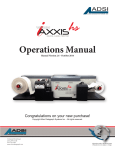
IMPORTANT: "Set" The Template Material
(Setting the material creates a stable track-path for processing
Template Material)
Once you have loaded the template material into the unit (matte
finish down), the material needs to be "Set". This is a quick
process that sets accurate tracking paths in the material. To set
the material, use the printer driver set unroll Media Before Plot
Count = 3, the automated process (#2. below) or the manual
process, (#3 below).
#1.
Using the set template material feature of the printer
driver. Select unroll media before plot, count = 6, send speed to
tool, set speed for tool #1, 2 (black, red), speed to pull media off
roll, speed to travel when the pen is up to 10%. To control the
speed from the driver you must also select cad override = off on
the Setup Settings menu of the remote panel.
U:\Manuals\TemplateMaker Manual\Material Processing w.TemplateMaker Manual Supplement.doc
Revised: June 30, 2006
Allen Datagraph Systems, Inc.
www.allendatagraph.com
2
#2.
Use the SetMedia6foot.plt (Web Site Copy / CD Copy) on or SetMedia12foot.plt (Web Site Copy / CD
Copy). These files are located on the CD that comes with the machine and can be copied to the “C:/Program
Files/Allen Datagraph/Sample” directory. Using the explorer you can copy the files from “<CD drive Letter>:\iTECH” directory to the sample directory.
A)
B)
C)
D)
E)
F)
G)
#3.
Open the Remote Panel Program
Click the "Action" drop down menu
Click on the "Send HPGL File"
Select the "SetMedia6foot.plt" or “SetMedia12foot.plt” file
Click, "Open"
Enter "1" as the number of copies
Click, "OK" (The unit will run a six or 12 foot path out and back six times.)
Using the joystick, manually move the material back and forth the length of your job two to three times.
Adjusting Operational Settings:
When you initially set-up to process your template material, you should perform test runs to verify your primary
settings are correct to deliver score-cut depth, length (X) and width (Y) accuracy you require. Although your unit
has been factory-set and calibrated for Allen AT-Media template material, you can adjust the Settings and recalibrate the tracking accuracy anytime.
Function Definitions:
Acceleration – The time it takes for tool movement to go from a standing position to the designated Move
Speed setting. Measured in "1/4 G" force increments.
Move Speed – The Speed at which the tool moves when not engaged with the material ("air time").
Measured in %.
Cut Speed
– Speed at which the tool moves when engaged with the material (cutting). Measured in %.
Force
– The amount of pressure applied to "force" the knife into the material. Measured in 5.5gram increments.
A: Function Settings for processing Allen AT-Media template material.
NOTE: Each Allen TemplateMaker is performance tested prior to shipment and calibrated to process Allen ATMedia template material. Factory systems are delivered with the settings below programmed as default settings.
When the unit is powered-up, the display will read: C 1 1 8. If desired, the operator has the option to change and
save any of these settings. (See the Allen i-Tech User Manual on the CD "Factory & Custom Set-ups").
Function TemplateMaker
Acceleration #
Move Speed
Cut Speed
Force %
Set-up Values
1
10%
10%
18%
B: Calibrating Length (X) and Width (Y) Travel Accuracy.
Recommended Template Material Calibration Test Procedure:
a) Load the AT-Media template material with the matte finish down.
b) "Set" the material.
c) Insert your Knife Tool and run a cut file at recommended settings.
Note:
-
-
Plot files are supplied within your Allen Remote-Panel (see "Automated Setting", above) for
use in calibration.
File - Tempcal.plt is a 144” X 4.5” plot with steps at 2,4,6,8 and 12 feet.
File - 20incal.plt is a 20” X20” plot.
U:\Manuals\TemplateMaker Manual\Material Processing w.TemplateMaker Manual Supplement.doc
Revised: June 30, 2006
Allen Datagraph Systems, Inc.
www.allendatagraph.com
3
-
Diagnostic Calibration Square Plot from i-TECH remote panel
Choose the one that best meets your accuracy needs. (Or you can create your own custom plot with your
design software.)
d) Remove the material from the cutter and lay on a flat surface. Using an accurate rule (precision steel
rule is recommended) measure the length (X) and width (Y). If the length (X) and width (Y) measures
exactly how the plot is constructed no further steps are required.
e) If there is a variance from the desired objective, record the exact ACTUAL LENGTH (X) and ACTUAL
WIDTH (Y) and perform the Diagnostic 07 calibration procedure.
General Information:
1) You will enter your X and Y axis measurements. It is important that you use the same number digits for each
entry. Accurate measurements are critical. Fractional measurements must be converted to decimal
equivalents. EXAMPLE: 96 1/4 inches will be entered as 96.25. (Conversion Table, below)
2) If an error is made, (new firmware will ignore the change, old firmware you will receive an "E37" error code in
the display). The only way to recover is to run Diagnostic 08, which resets the factory default calibration
constants. Following this Diagnostic 08 procedure, you will need to start your calibration test over from the
beginning. (Diagnostic 08 is described in detail further in this document) (E37 Error Code = "bad calibration
constants")
DIAGNOSTIC 07 CALIBRATION PROCEDURE:
Use the Allen Remote-Panel Program
a)
b)
c)
d)
Open the Remote-Panel Program
Click on the "Diagnostics" drop-down menu
Click on "Calibrate 07".
Enter your "X Drawn" (X Drawn = your desired Length Objective)
i.e. 96"
Enter: 96
e) Enter your "X Measured" (X Measured = your Actual measured Length)
i.e. 96 1/4"
Enter: 96.25
f) Enter your "Y Drawn" (Y Drawn = your desired Width Objective)
i.e. 28"
Enter: 28.
g) Enter your "Y Measured" (Y Measured = your Actual measured Width)
i.e. 28 1/4"
Enter: 28.25
h) Click "OK"
i) (Confirm Dialog Box appears) Click "yes". The percentage of change for the X and Y is displayed.
Tip: It is recommended that you repeat this test cut and re-measure to confirm the calibration has achieved
your objective.
After calibrating you can save your calibration to your hard drive from the i-TECH remote panel and clicking
on Action -> Save Calibration. This calibration can be restored with Action -> Restore Calibration.
DIAGNOSTIC 08 PROCEDURE:
You will need to run Diagnostic 08, if you received an E-37 error message during your calibration procedure. D-08
restores the cutter to the standard operating default settings.
Use the Remote-Panel Program:
a)
b)
c)
d)
Open the Remote-Panel Program
Click the "Action" drop down menu
Click on "Default Calibration 08"
Follow the on-screen directions.
Note: 1. Since D-08 restores to standard factory defaults you will want to replot your Calibration Square with the
default settings and remeasure the square prior to running diagnostic 7 again. Once you have calibrated your
machine you can save the calibration and settings to your hard drive so they can be restored at a later time.
4
U:\Manuals\TemplateMaker Manual\Material Processing w.TemplateMaker Manual Supplement.doc
Revised: June 30, 2006
Allen Datagraph Systems, Inc.
www.allendatagraph.com
Fraction to Decimal Conversion Chart
1/64
1/32
3/64
1/16
5/64
3/32
7/64
1/8
9/64
5/32
11/64
3/16
13/64
7/32
15/64
1/4
.016
.031
.046
.062
.078
.093
.109
.125
.140
.156
.172
.187
.203
.219
.234
.250
17/64
9/32
19/64
5/16
21/64
11/32
23/64
3/8
25/64
13/32
27/64
7/16
29/64
15/32
31/64
1/2
.266
.281
.297
.312
.328
.343
.359
.375
.391
.406
.422
.437
.453
.469
.484
.500
33/64
17/32
35/64
9/16
37/64
19/32
39/64
5/8
41/64
21/32
43/64
11/16
45/64
23/32
47/64
3/4
U:\Manuals\TemplateMaker Manual\Material Processing w.TemplateMaker Manual Supplement.doc
.516
.531
.547
.562
.578
.594
.609
.625
.641
.656
.672
.687
.703
.719
.734
.750
49/64
25/32
51/64
13/16
53/64
27/32
55/64
7/8
57/64
29/32
59/64
15/16
61/64
31/32
63/64
1.0
Revised: June 30, 2006
Allen Datagraph Systems, Inc.
www.allendatagraph.com
.766
.781
.797
.812
.828
.844
.859
.875
.891
.906
.922
.937
.953
.969
.984
1.000
5