1
µALFAT User Manual
Rev. 3.11
Date: October 1, 2009
User Manual
Document Information
Information
Description
Abstract
This document covers complete information about
µALFAT, specifications, tutorials, and references.
G H I
E l e c t r o n i c s
GHI Electronics,LLC
µALFAT User Manual
Table of Contents
Table of Contents
1.Introduction..........................................................................................................................3
1.1.µALFAT General Description:......................................................................................3
1.2.Example applications:..................................................................................................4
1.3.Key features.................................................................................................................4
1.4.OEM Circuit Boards.....................................................................................................4
1.5.μALFAT special firmware.............................................................................................5
2.µALFAT Architecture...........................................................................................................7
2.1.Block Diagram..............................................................................................................7
2.2.Commander.................................................................................................................8
2.3.FAT File System...........................................................................................................8
2.4.USB Hosting................................................................................................................8
2.5.What's new in μALFAT Version 3.................................................................................8
3.Pin-Out and Description....................................................................................................10
4.Commanding μALFAT.......................................................................................................12
4.1.Selecting an Interface................................................................................................12
4.2.UART Interface..........................................................................................................12
4.3.SPI Interface Mode....................................................................................................12
4.4.I2C Interface Mode....................................................................................................14
5.Getting Started with µALFAT.............................................................................................16
6.μALFAT™ Commands Set................................................................................................20
7.FAT and Long File Name Support.....................................................................................34
7.1.Short and Long File Names.......................................................................................34
7.2.Handling File Names and Licensing..........................................................................35
7.3.Using the FAT File System........................................................................................36
8.µALFAT Boot Loader.........................................................................................................39
8.1.General Description...................................................................................................39
8.2.Firmware Update.......................................................................................................39
8.3.Boot Loader Commands............................................................................................40
9.Power Modes....................................................................................................................41
10.Required μALFAT Components......................................................................................42
11.Error Codes.....................................................................................................................43
DISCLAIMER.......................................................................................................................48
GHI Electronics,LLC
µALFAT User Manual
Introduction
1. Introduction
1.1. µALFAT General Description:
Adding a file system, such as FAT, to products requires a lot of resources, not to forget the
work involved in licensing the patented technologies, such as LFN. USB Host drivers and
SD memory drivers are also other challenges. Thanks to μALFAT, companies can now
access files on SD cards and USB memories in a very short time with very little resources.
µALFAT chipset is a full FAT (FAT16/FAT32) file system and USB/SD drivers on-a-chip.
μALFAT requires very few external components to run. For communication, a simple
microcontroller (PIC, AVR, basic stamp…etc.) with UART, SPI or I2C can be used.
Basically, serial commands are sent to μALFAT to perform different tasks on the targeted
media. MMC and SD memory cards can be accessed directly. USB Mass Storage Devices
are accessed through a USB Host Controller (MAX3421E). Also, μALFAT supports Long
File Name technology and International Languages represented by UNICODE format. It is
licensed by Microsoft for the use of FAT File System and LFN (Long File Name) so it can
be commercially used without any worries about patents or licensing issues*.
The firmware in μALFAT is in-field upgradeable. Updates are available on GHI website
and can be loaded on μALFAT by simply placing the file on a media and issuing the update
command.
* See LFN support and licensing section for details
Rev. 3.11
Page 3 of 48
www.ghielectronics.com
GHI Electronics,LLC
µALFAT User Manual
Introduction
1.2. Example applications:
●
●
●
●
●
●
Digital cameras
Printers
Digital picture viewer
MP3 players
Data logger
Automated machines
1.3. Key features
●
●
●
●
●
●
●
●
●
●
●
●
●
●
●
●
●
●
●
●
Full FAT16 and FAT32
Files and Directories support
Licensed Long File Name support (V3.11 and above)*
Runs over UART, SPI or I2C
Programmable UART (serial port) baud-rate.
Up to 4 simultaneous file access
Fast startup and media reconnect, about a second
Fast file write and read. Average of 60 KBytes/Sec
Supports Secure Digital (SD)and Multi Media Card (MMC)
Supports SD High Capacity (SDHC) (Firmware Version 3)
Supports USB Mass Storage Devices like thumb drives and card readers
Field upgradeable firmware through a file on the connected media
Very few external components required
RTC (Real Clock Time) capable of running on external battery
Low power consumption, 12mA
Three power modes
All I/O pins are 5 volt tolerant
Small surface mount package, LQFP 48 pin
-40˚C to +85˚C temperature operating range
Lead free
* See LFN support and licensing section for details
1.4. OEM Circuit Boards
μALFAT-TF
Rev. 3.11
Page 4 of 48
www.ghielectronics.com
GHI Electronics,LLC
µALFAT User Manual
Introduction
μALFAT-TF is an OEM board of μALFAT™ chip with TransFlash (micro SD) card
connector. It has very small dimensions which makes it ideal for small data logger. This
OEM board is one of the smallest OEMs with high performance file system abilities ,
about 1" by 1.4"!
μALFAT-SD
μALFAT-SD is an OEM board of μALFAT™ chip. The low cost and the ease of use,
makes μALFAT-SD the ultimate solution for OEMs and hobbyists.
μALFAT-USB
Similar to μALFAT-SD but with USB connector
1.5. μALFAT special firmware
μALFAT chipset can handle different firmwares:
Rev. 3.11
Page 5 of 48
www.ghielectronics.com
GHI Electronics,LLC
µALFAT User Manual
Introduction
μALFAT firmware
μALFAT firmware supports FAT file system with Long File Name support and can
access FAT file system on USB Mass Storage devices and SD cards. This manual
explains this firmware in details
GHI3232 firmware
GHI3232 is much simpler firmware. No commands are available and all data received
are saved on the media.
For more information, refer to GHI3232 User Manual
Rev. 3.11
Page 6 of 48
www.ghielectronics.com
GHI Electronics,LLC
µALFAT User Manual
µALFAT Architecture
2. µALFAT Architecture
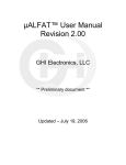
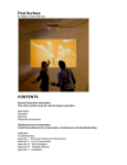
µALFAT is a combination of powerful features on compact LPC2103 micro controller from
NXP with a great software architecture from GHI Electronics that provides an easy
interface to any other system, through UART, SPI or I2C. It includes a robust and fast FAT
file system that accesses MMC/SD Cards and USB mass storage devices through a USB
Host Controller (MAX3421E).
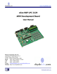
2.1. Block Diagram
UART,SPI
or I2C
FAT File System
Driver
SD/MMC
SPI Dirver
Simple Commander
USB Host driver with
Mass Storage Class driver
SD/MMC
SPI
SPI
Developer's System
AVR, PIC ...etc
USB Host Controller
MAX3421E
USB
Mass Storage
Device
μALFAT LPC2103
Rev. 3.11
Page 7 of 48
www.ghielectronics.com
GHI Electronics,LLC
µALFAT User Manual
µALFAT Architecture
2.2. Commander
The main function of commander is to provide the user with a simple tool to control
µALFAT to get the full use of its functions.
UART, SPI or I2C are used to let the user communicate with the firmware. All commands
are entered in ASCII characters. ASCII is used to simplify troubleshooting and to allow
commands to be typed manually or coded in software easily.
2.3. FAT File System
FAT support can connect to two kinds of storage media types. The media types are
SD/MMC cards and USB Mass Storage device (SCSI command subclass, bulk only
protocol) which includes thumb flash, USB hard drives and card readers. Keep in mind that
all devices must be formatted FAT16 or FAT32.
Some supported FAT File System features:
●
FAT16, FAT32
●
Licensed Long File Names (V3.11 and up)*
●
Access up to 4 opened files simultaneously
●
Access directories (folders)
●
File access functions include read, write, append, seek, tell, find, delete, make
folder, remove folder ...etc
●
Modification of files at random offsets using Seek and Tell
* See LFN support and licensing section for details
2.4. USB Hosting
USB hosting is done through MAX3421E USB Host Controller chip. μALFAT
architecture includes USB hosting driver in addition to Mass Storage Device driver (SCSI
command subclass, bulk only protocol) which includes thumb flash, USB hard drives and
memory card readers.
2.5. What's new in μALFAT Version 3
μALFAT3 is a complete rebuilt version of the previous μALFAT firmwares. It has an all new
USB stack engine and a very robust FAT system structure. In μALFAT3, you can enjoy all
the features of μALFAT2 and more. μALFAT2 firmware is denoted by versions 2.xx,
whereas, μALFAT3 firmware is denoted by version 3.xx
Some new features are:
●
Long file name support*
Rev. 3.11
Page 8 of 48
www.ghielectronics.com
GHI Electronics,LLC
µALFAT User Manual
µALFAT Architecture
●
File Seek/Tell: μALFAT can change any contents of a file without affecting the rest of
the data. This is done using Seek to change the current position in a file and Tell to
get the current position in a file.
* See LFN support and licensing section for details
Application running on μALFAT2 should work fine with μALFAT3. However, the new
internal engines of μALFAT3 handle data differently and might return a different error code
than μALFAT2. If the user is not checking for specific error codes, which should be the
case for most users, the transfer to μALFAT3 is transparent.
Migrating from μALFAT2 to μALFAT3
If the user is moving from V2 software to V3, attention should be taken for the N
command if using Long File Names.
“N” command returns the next short name directory in a list. This command behaves the
same in μALFAT3 and is provided for backward compatibility reasons only. In order to
correctly report the next directory name with long name support, a new command is
added, the “L” command which gets the next long name in a list when LFN is enabled.
Here are the cases the user would encounter with the “N” command when upgrading to
Version 3 firmware:
●
The user does not use this command in the existing system: No change is
necessary.
●
The user uses this command in the existing system and will always use valid
short names: No change is necessary. Note that short names only use capital
letters, if a non-capital letter is encountered, it is treated as long name.
●
The user uses this command in the existing system and is looking to use long
names in the future: The “N” command should be replaced with the new “L”
command.
Rev. 3.11
Page 9 of 48
www.ghielectronics.com
GHI Electronics,LLC
µALFAT User Manual
Pin-Out and Description
3. Pin-Out and Description
The following Table includes a brief description of µALFAT chipset pins.
Note: The schematics of μALFAT OEM boards should be used as a reference design. The
OEM boards are μALFAT-SD, μALFAT-USB and μALFAT-TF.
Advanced details on oscillator and power tolerance can be found in the LPC2103 data
sheet from NXP website.
Pin µALFAT Name
Description
1
SD_MISO
SD card signal
2
SD_MOSI
SD card signal
4
VBAT
Power source for the internal RTC. Connect to 3V battery or
VCC. Always use 2 diodes to connect a battery and VCC in case
the battery runs out of power.
This pin must have power, even if the internal RTC is not
needed.
5
VDD 1.8V
1.8V power source
6
RESET#
Reset signal. Must be high for μALFAT to operate
7
VSS
Ground
8
TRST#
Do not connect
9
TMS
Do not connect
10
TCK
Do not connect
11
X1
Pin 1 for 10 MHz oscillator
12
X2
Pin 2 for 10 MHz oscillator
UART_TX
UART mode: Transmit pin of UART (output)
SPI_DATARDY
I2C_DATARDY
SPI and I2C modes: When high, it signals that μALFAT wants to
send some data and the host must read it.
UART_RX
Receive pin of UART (input)
14
SPI_BUSY
I2C_BUSY
SPI and I2C: When high, it signals that μALFAT is busy and not
ready for new data
15
TDI
Do not connect
16
TDO
Do not connect
17
VCC
3.3V power source
13
Rev. 3.11
Page 10 of 48
www.ghielectronics.com
GHI Electronics,LLC
µALFAT User Manual
Pin-Out and Description
Pin µALFAT Name
Description
18
I2C_SCL
Clock pin for I2C
19
VSS
Ground
20
RTXC1
Pin 1 for 32.768 KHz oscillator. Optional, for RTC with backup
battery
21
I2C_SDA
Data pin for I2C
22
SPI_SCK
Clock pin for SPI
UART_RTS
For UART, do not send data to μALFAT when this pin is high.
SPI_MISO
For SPI, Master In Slave out (output)
UART_CTS
For UART, μALFAT will only send data if this pin is low. If not
needed then connect to ground.
SPI_MOSI
For SPI, Master Out Slave In (input)
25
RTXC2
Pin 2 for 32.768 KHz oscillator. Optional for RTC with backup
battery.
26
RTCK
Do not connect
27
DBGSEL
Do not connect
28
SPI_SSEL#
Slave Select for SPI (input)
31
VSSA
Analog Ground
36
CD_SSEL#
SD card signal
37
MISC
A miscellaneous pin. Functionality will be determined in special
releases only.
38
UH_SSEL#
USB host slave select
39
UH_RESET#
USB host reset
40
VCC
3.3V Power source
42
VCC
3.3V Power source
43
VSS
Ground
SD_SCK
SD card signal
44
BL#
WAKE
This pin must be high when RESET# is low. Also, when sending
deep sleep command, a toggle on this pin will wake up μALFAT
45
UH_GPX
USB host GPX
46
UH_INT
USB host interrupt
23
24
•
All pins that are not listed in the table above must be left unconnected. Always, consult μALFAT-SD schematics.
•
Pins ending with the symbol ‘#’ are active low.
Rev. 3.11
Page 11 of 48
www.ghielectronics.com
GHI Electronics,LLC
µALFAT User Manual
Commanding μALFAT
4. Commanding μALFAT
4.1. Selecting an Interface
μALFAT uses UART, I2C or SPI to communicate with any external microcontroller. At
power up, μALFAT samples SPI_SSEL# and SPI_SCK pins to determine what interface to
use. The following table describes the states:
SPI_SSEL# SPI_SCK
Interface
0
0
UART
0
1
Stay in boot loader*
1
0
I2C
1
1
SPI
* In this mode the boot loader will not execute the firmware and will run UART at 9600 baud.
4.2. UART Interface
In UART interface mode, UART_TX pin is used to send data to your microcontroller and
UART_RX pin to receive commands from your microcontroller. The default baud rate for
UART is 9600. Always use 8 bit with no parity and 1 stop bit. Baud rate can be changed
through the commands. CTS and RTS lines must be used to insure no data loss at high
speeds. CTS pin is an input to μALFAT and when it is high μALFAT will not send data and
will wait for it to go low. CTS should be low as long as possible to not slow down μALFAT.
RTS pin is output from μALFAT and it is set high when μALFAT FIFO is full. Depending on
data transfer speed, RTS pin may never go high because μALFAT is contentiously
emptying the FIFO.
Note: The internal UART have hardware TX FIFO that is 16 byte long. After asserting
CTS, μALFAT may still send the internal FIFO, up to 16 bytes.
Important: μALFAT will NOT send any data if CTS pin is high. If this pin is not used, it
must be connected to ground.
4.3. SPI Interface Mode
In SPI mode six pins are used for communication, to implement slave SPI. Two pins are
used for handshaking. SPI_SSEL, SPI_SCK, SPI_MISO, and SPI_MOSI are the standard
Rev. 3.11
Page 12 of 48
www.ghielectronics.com
GHI Electronics,LLC
µALFAT User Manual
Commanding μALFAT
SPI pins where SSEL is used for Slave Select, SCK is the Serial Clock, MISO is the data
line going from μALFAT to your microcontroller, and MOSI is the data line going from your
microcontroller to μALFAT.
The Handshaking lines are SPI_DATARDY and SPI_BUSY. When μALFAT has data to
send to the PC, it raises DATARDY line. The host (SPI master) must read the data from
μALFAT as fast as possible. Data and commands can be sent to μALFAT at any time
except when SPI_BUSY is high.
In the nature of SPI, the data flow is full duplex. On every SPI transaction, a byte is
swapped between the master (your system) and the slave (μALFAT). This is great until you
need to read data from μALFAT but you don’t want to send a command. μALFAT
implements a software mechanism to handle this issue. Two special numbers are used to
handle the flow control. 0xFF and we will call it NDT (No Data Token) and 0xFE and will
call it HDT (Half Data Token) Whenever μALFAT SPI sees NDT (again, it is 0xFF,) it will
ignore it. This allows you to read μALFAT without sending data. Of course you are sending
NDT but it will be ignored by μALFAT SPI driver.
This is everything you need to do if you are using numbers from 0 to 0xFD. Usually, this is
good in most cases as μALFAT commands are ASCII based and most users save files as
ASCII text. If you need to send 0xFF to μALFAT, you have to send HDT followed by any
number between 0x00 and 0xFD. μALFAT will understand this as real 0xFF number and
will not ignore it. For 0xFE, you have to send HDT followed by a second HDT.
Here is a simple example in ‘C’ language on how your transmit routine should work:
SendData(char c)
{
if( c == 0xFF )
{
SendSPI(0xFE);
SendSPI(0);
}else if (c == 0xFE )
{
SendSPI(0xFE);
SendSPI(0xFE);
}else
SendSPI(c);
}
If polling is preferred, it is possible to keep polling μALFAT and not check DATARDY pin at
all. When there is no data, μALFAT will return NDT (0xFF).
Important: μALFAT requires the following in order for SPI to work:
●
SCK is output from your system.
Rev. 3.11
Page 13 of 48
www.ghielectronics.com
GHI Electronics,LLC
µALFAT User Manual
Commanding μALFAT
●
SCK is idle high.
●
SCK is slower than 8 MHz in full power mode and slower than 1.25 in reduced
power mode.
●
Data is shifted out MSB first.
●
Data is latched on the rising edges.
For further details and timing diagrams, consult LPC2103 data sheet and manual from
NXP Semiconductor.
4.4. I2C Interface Mode
I2C was completely updated starting with firmware version 3.05. The new setup can run
with 2 wires only and it is more solid.
Before version 3.05 and all version 2.xx
Four pins are needed for I2C communication. The USER_I2C_SCL and
USER_I2C_SDA are the two I2C bus lines. I2C_DATARDY and I2C_BUSY lines work
exactly the same way as SPI_DATARDY and SPI_BUSY work except the interface is
half duplex. When DATARDY is high, you can’t send data to μALFAT until all the data is
read and DATARDY is back low. μALFAT runs in slave I2C mode always. The slave
address of μALFAT is 0xA4 with maximum clock on 400K. This address is fixed and
can’t be changed.
Firmware version 3.05 and above
The handshaking pins, DATARDY and BUSY are still available if user wants to use them
but they are not required. DATARDY indicates that μALFAT has some data to send
when it is high and BUSY flags that μALFAT input buffer is full and no more data should
be sent.
If data is requested from μALFAT over I2C and μALFAT has no data to send back then it
responds with 0xFF (No Data Token). Users who do not wish to use DATARDY can pool
μALFAT till it responds with any value other than 0xFF.
Now, if μALFAT really needs to send 0xFF (returning binary data from a file) then it will
send back 0xFE followed by 0x00. 0XFE (Half Data Token) is another special number.
To return 0xFE, μALFAT send back 0xFE followed by 0xFE.
This is the same as how HDT and NDT are handed in SPI.
Note that this is only for data coming back from μALFAT. If you need to send 0xFF then
there is no need to do anything special, simply send 0xFF.
To get away without the need to check BUSY, we have to make sure that file write
chunks are less than or equal to 100 bytes. Everything else will work fine as long as the
response is read after every issued command. So, for any command such as read file
Rev. 3.11
Page 14 of 48
www.ghielectronics.com
GHI Electronics,LLC
µALFAT User Manual
Commanding μALFAT
or create directory...etc. there is no need for checking BUSY pin. Only when a user is
writing file, the data sent has to be in chunks of 100 bytes or less. The final file size can
be of any size.
The slave address is 0xA4 with maximum clock speed of 400K.
Here is a simple example code for the receive routine written in C:
char Get_I2C_Data()
{
char c;
do{
c = Get_I2C_Data_lowlevel();
}while(c == 0xFF); // timeout maybe needed here
if( c == 0xFE )
{
c = Get_I2C_Data_lowlevel();
if(c == 0xFE)
return 0xFE;
return 0xFF
}
return c;
}
char Get_I2C_Data_lowlevel()
{
I2C_Start();
I2C_Write(ADDRESS+1); // read from 0xA4
c = I2C_Read();
I2C_Stop();
return c;
}
Rev. 3.11
Page 15 of 48
www.ghielectronics.com
GHI Electronics,LLC
µALFAT User Manual
Getting Started with µALFAT
5. Getting Started with µALFAT
The following chapter includes steps to get μALFAT working for first time user and that is
through UART interface.
All you need:
●
one of μALFAT OEM boards, μALFAT-SD for instance.
●
RS232 adapter connected to UART Tx/Rx and connected to PC COMx .
●
PC COMx opened through terminal program.
●
μALFAT latest firmware.
Step-by-Step:
1. Confirm that all hardware connections are made:
Rev. 3.11
○
Ground SPI_SSEL# and SPI_SCK signals to access UART interface.
○
Power is connected to power and VBAT.
○
RS232 adapter signals connections and let's assume it is connected to PC
COM4. If CTS and RTS signals are not available, user can ground CTS.
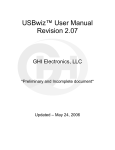
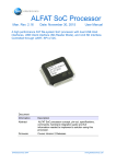
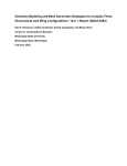
Note that μALFAT and the OEM boards are TTL levels and UART signals are
0V to 5V, but the PC is RS232 -12V to 12V, therefore, you need a RS232
circuit. There are some RS232 converters available such as MAX3232. See
schematic below:
Page 16 of 48
www.ghielectronics.com
GHI Electronics,LLC
µALFAT User Manual
Getting Started with µALFAT
Other options are using USB to UART modules or cables. You will have a virtual
COM port on your PC that communicates with μALFAT. Examples are UM232R
and TTL-232R from FTDI
2. Open COM port using a terminal program, for example TeraTerm, and ensure the
baud rate is 9600, 8 data bits, 1 stop bit and no handshaking.
Rev. 3.11
Page 17 of 48
www.ghielectronics.com
GHI Electronics,LLC
µALFAT User Manual
Getting Started with µALFAT
3.
Select to receive a line end with the line feeds (LF+CR), because μALFAT only
sends CR. For transmitting, only CR should be sent.
4. Reset the chip and you will get the GHI electronics starting banner.
GHI Electronics, LLC
-----------------------------Boot Loader x.xx
μALFAT(TM) x.xx
!00
5. To update firmware please refer to boot loader chapter in this document.
First Look
The commands and responses in μALFAT are made in a way were they can be
understood easily and entered manually and also can be parsed by a simple 8-bit
microcontroller. Each command is one character. Some commands take parameters
and others don’t. For example, V command doesn’t take any parameters and it returns
the version number. On the other hand, M requires a parameter to run. M creates
“Makes” a folder on the accessed media device. ‘M LOG’ creates a folder with the name
LOG.
Also, every command must be terminated with a carriage return. This is the enter key
on your keyboard. When programming in ‘C’, it is ‘\r’ or 0x0D.The backspace key is not
supported. Make sure to follow the command format in the provided command set,
otherwise, μALFAT will not accept the command.
Since all commands are text based, a user can use a terminal program to type in the
commands (if using a PC and RS323 level converter.)
Important: μALFAT doesn’t echo back the data by default. Use ‘# 1’ command to
enable echo if needed.
Rev. 3.11
Page 18 of 48
www.ghielectronics.com
GHI Electronics,LLC
µALFAT User Manual
Getting Started with µALFAT
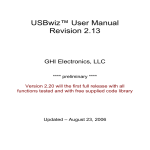
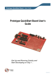
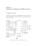
uPICFAT™ Development Board
For even easier and faster startup, GHI offers a development system for μALFAT and
USBwiz. This is the component that provides power and communication to
μALFAT/USBwiz. It also provides the serial interface to your computer, and contains the
PIC micro controller PIC18F452 that will be used to interface to μALFAT/USBwiz .
Complete with a programming port for direct interface to the ICD 2™ programmer.
uPICFAT provides both 3.3V and 5.0V
Rev. 3.11
Page 19 of 48
www.ghielectronics.com
GHI Electronics,LLC
µALFAT User Manual
μALFAT™ Commands Set
6. μALFAT™ Commands Set
All commands below are entered in ASCII. We choose to use ASCII to simplify
troubleshooting and to enter commands easily through a terminal program. A special case
is when accessing the data in a file. When writing/reading to/from a file, μALFAT will use
any kind of data. Basically, what you send is what goes on the file. It doesn’t have to be
ASCII.
When μALFAT is done processing a command, it will return an error code in the form “!
xx<CR>” where xx is the error number. Also, some commands require returning some
extra information. Returned data will come after the symbol $, unless noted otherwise.
You can send multiple commands to μALFAT until its FIFO is full (indicated by BUSY or
RTS). μALFAT will take the commands one at the time, process them and send responses
for each one.
All of the commands are supported by μALFAT2 and μALFAT3, unless otherwise indicated.
Command Description
Command Description
V
Get Version Number
#
Enable Echo
Z
Set Power Mode
T
Initialize Timer
S
Set Current Time and Date
G
Get Current Time and Date
B
Change Baudrate
I
Initialize and Mount MMC/SD
U
Initialize and Mount USB
J
Detect USB Device
K
Get Media Statistics
@
Initialize Directory List
N
Get Next Directory Entry
L
Get Next Directory Entry (N
command new version)
M
Make Directory
A
Change Directory
O
Open File
F
Flush File
C
Close File
R
Read File
W
Write File
P
File Seek
Y
File Tell
D
Delete File
E
Delete Folder
?
Find File or Folder
Q
Quick Format
X
Update Firmware
~
Check LFN License
Rev. 3.11
Page 20 of 48
www.ghielectronics.com
GHI Electronics,LLC
µALFAT User Manual
μALFAT™ Commands Set
Notes on commander:
●
Any command must not exceed 200 bytes and must be terminated with a carriage
return.
●
The user must read back the responses for each command properly and check
whether the command was successful.
●
The command format must be followed with the same number of arguments. Also,
extra spaces count as errors.
●
All numbers are Hexadecimal represented in ASCII. For example, to send the
decimal number 16 to μALFAT which is 10 in Hexadecimal, you send 0x31 which is
ASCII for 1 and 0x30 which is ASCII for 0. Also, for Hexadecimal numbers A to F,
they must be entered in upper case letters.
●
In all command's output description below, will assume the commands succeeded.
In case of failure, the command would return an error code instead of success and
halt. In other words, in any command, a !00 denotes success and the command can
resume operation. But in case of failure, the error code is !xx, where xx is the error
number and then the current command halt and the commander resume processing
further commands.
●
Some commands have multiple error codes !xx, usually, the first error code denotes
the command is accepted and then it is processed. Another error code is sent when
the command has finished processing successfully. This is useful, because some
commands can take some time to finish, so the first error can note that the
command is accepted and then the user can do other application processing and
then return to read the final error code.
●
Below, data sent to μALFAT are BLACK and data received are RED. <CR> is a
carriage return which is the Enter key on a keyboard, ASCII value 0x0D or in C
language '\r'. <SP> is a space which is ASCII value 0x20.
●
File/Folder names has a certain format and certain accepted characters according
to the FAT File System. See Supported File Names section for details.
V - Get Version Number
Prints the version number of μALFAT firmware. Note that this version is not same or
related to the version number of the boot loader. The return value is always in the form
“μALFAT x.xx”
Format
V<CR>
μALFAT<SP>x.xx<CR>
!00<CR>
Returns version number
Example V<CR>
μALFAT<SP>3.11<CR>
Rev. 3.11
Page 21 of 48
www.ghielectronics.com
GHI Electronics,LLC
µALFAT User Manual
μALFAT™ Commands Set
!00<CR>
# - Enable Echo
μALFAT by default does not echo back the data that it received from the host, if Echo is
required, this command can be used.
Format
#<SP>n<CR>
!00<CR>
n = 0 Disable echo
n = 1 Enable echo
Example #<SP>1<CR>
!00<CR>
Enable echo
Z - Set Power Mode
Read Power Modes Section for details.
Format:
Z<SP>F>xxxx<CR>
!00<CR>
!00<CR>
Full power
xxxx is Baudrate (2 Bytes)
First !00 is sent before changing power
Second !00 is sent after changing power
Z<SP>R>xxxx<CR>
!00<CR>
!00<CR>
Reduced power
xxxx is Baudrate (2 Bytes)
First !00 is sent before changing power
Second !00 is sent after changing power
Z<SP>H<CR>
!00<CR>
!00<CR>
Hibernate Mode
First !00 is sent before Hibernating
Second !00 is sent after Hibernating
T - Initialize Timer
Format:
T<SP>S<CR>
!00<CR>
Share Mode. The RTC runs from the
same processor clock.
T<SP>B<CR>
!00<CR>
Backup Mode. Run RTC from 32Khz
external crystal and battery so it will keep
the time even if the processor power is
off.
S - Set Current Time and Date
Format
S<SP>ddddtttt<CR>
!00<CR>
Example S<SP>34210000<CR>
!00<CR>
Rev. 3.11
ddddtttt time and date 32bit structure*
Set 1/1/2006 00:00:00
Page 22 of 48
www.ghielectronics.com
GHI Electronics,LLC
µALFAT User Manual
μALFAT™ Commands Set
G – Get Current Time and Date
Format
G<SP>X<CR>
!00<CR>
$ddddtttt<CR>
!00<CR>
Get 32bit standard time and date
structure*
Format
G<SP>F<CR>
!00<CR>
Get time and date in a formatted
string
MM/DD/YYYY<SP>–<SP>HH:MM:SS<CR>
!00<CR>
Example G<SP>X<CR>
!00<CR>
$34210000<CR>
!00<CR>
Example G<SP>F<CR>
!00<CR>
01/01/2006<SP>-<SP>00:04:04<CR>
!00<CR>
* Time and Date structure is a 32-bits standard structure used in FAT system. For
example, 0x34212002 is 01/01/2006 – 04:00:04
0x34212000 Bits in Binary
Bits(s)
Field
Description
31..25
Year1980 Years since 1980
24..21
Month
1..12
0001
20..16
Day
1..31
0 0001
15..11
Hour
0..23
0 0100
10..5
Minute
0..59
00 0000
4..0
Second2
Seconds divided by 2 (0..30)
001 1010
0 0010
B - Set UART Baud Rate
μALFAT contains a fancy divider for baud rate. Using the divider, the UART can be set
to almost any possible baud rate. Below is a table with some standard baud rates. Note
that the values do not work in boot loader. Always run boot loader at default 9600 and
Rev. 3.11
Page 23 of 48
www.ghielectronics.com
GHI Electronics,LLC
µALFAT User Manual
μALFAT™ Commands Set
after firmware execution, change the baud rate. The table contains two sets of divider
values, at 10 MHz and 70 MHz. Use the 70 MHz when run in full power mode and the
10 MHz when running reduced power mode.
Baud Rate
Divider at 70 MHz
Divider at 10 MHz
9600
DCEF
1FAB
19200
6EEF
0C7C
38400
37EF
067C
57600
43F2
08E5
115200
1EF4
04E5
230400
0FF4
02E5
460800
05A9
01E5
921600
028B
Not possible!
For example: B 1EF4 will set the baud rate to 115200 when using full power mode.
μALFAT responds with !00 if command is accepted at the old baud rate, waits 200 ms
and then changes to the new baud rate. You will then receive a second !00 at the new
baud rate. The user, after receiving the first !00, should change the baud rate within 200
ms and then read the second !00 at the new baud rate. Otherwise, the received !00
could be corrupted! However, the user can still continue normal operations after
receiving all data.
Format
B<SP>vvvv<CR>
!00<CR>
!00<CR>
vvvv: 2 Bytes in HEX Baud Rate Divider
First !00 is sent before changing baudrate
Second !00 is sent after changing
baudrate
Example B<SP>1EF4<CR>
!00<CR>
!00<CR>
Baud Rate is 115200
I - Initialize and Mount MMC/SD
It is a major initializing command which is used to mount File System on a newly
attached MMC/SD, or to re-mount it. All file handles will be closed automatically.
After using this command the current working directory is the root directory (created
files/folders will be placed right on the storage media not under any folder).
Format
Rev. 3.11
I<CR>
Page 24 of 48
www.ghielectronics.com
GHI Electronics,LLC
µALFAT User Manual
μALFAT™ Commands Set
!00<CR>
U - Initialize and Mount USB Mass Storage
It is a major initializing command which is used to mount File System on a newly
attached USB Mass Storage Device like USB thumb flash, or to re-mount it. All file
handles will be closed automatically.
In case that the Mass Storage device has more than one Logical Unit – like Card
Readers – the first Unit will be used.
After using this command the current working directory is the root directory (created
files/folders will be placed right on the storage media not under any folder).
Format
U<CR>
!00<CR>
J - Detect USB Device
Detects if a USB device is connected.
Format
J<CR>
!00<CR>
$xx<CR>
!00<CR>
Note: If you are using this command:
xx Device Status:
02 New device is connected.
01 Device is connected.
00 Device is not connected.
●
Status “02” is reported when a new USB drive is connected then “01” is reported.
●
Only use “U” command after detection of a connected USB device.
K - Get Media Statistics
Gets media total size and free size. Note this command may take several seconds for
calculations to finish depending on the media size.
Format
K<CR>
!00<CR>
$ssssssss<SP>$ffffffff<CR>
!00<CR>
ssssssss 4 bytes in HEX media size
in sectors
ffffffff 4 bytes in HEX free size in
sectors
Every Sector is 512 Bytes
First !00 is sent before starting
calculations
Example K<CR>
Size Available - 128 MB
!00<CR>
Size Free – 120 MB
$00040000<SP>$0003C000<CR>
!00<CR>
Rev. 3.11
Page 25 of 48
www.ghielectronics.com
GHI Electronics,LLC
µALFAT User Manual
μALFAT™ Commands Set
@ - Initialize Files and Folders List
To list files/folders in the current directory, first use this command to reset the list
counter. Afterwards, the user should get as much directory names as needed using N, L
commands.
No other commands can be issued among multiple N, L commands. If issuing another
command is needed, the user must use @ command again before calling N, L.
Format
@<CR>
!00<CR>
N - Get Next Directory Entry (Deprecated)
In μALFAT3 this command is replaced with the L command to get Long File Names.
The @ command must be used to reset the directory list to the beginning before issuing
N commands. This command will print out the next Directory Entry “File or Folder” in the
list. The file name and extension are 8 and 3 characters respectively and padded with
spaces (ASCII value 0x20) if they are shorter.
When the end of the file list is reached, μALFAT returns an error indicating the end of
the list.
Format
N<CR>
!00<CR>
!00<CR>
NNNNNNNN File Name (8
Chars)
EEE File Extension (3 Chars)
AA 1 byte in HEX File
Attributes*
ssssssss 4 bytes in HEX file
size
Example N<CR>
!00<CR>
Passing N command two
times and getting the results.
NNNNNNNN.EEE<SP>AA<SP>ssssssss<CR>
TEST0001.TXT<SP>00<SP>0000FE23<CR>
!00<CR>
N<CR>
!00<CR>
TEST0002.TXT<SP>00<SP>00001234<CR>
!00<CR>
* File Attributes are one byte Standard Attribute Structure in FAT system.
7
6
Reserved
Rev. 3.11
5
4
3
Archive Folder
2
1
0
Volume System Hidden Read
ID
Only
Page 26 of 48
www.ghielectronics.com
GHI Electronics,LLC
µALFAT User Manual
μALFAT™ Commands Set
L - Get Next Directory Entry
Only applicable to μALFAT3.
The @ command must be used to reset the directory list to the beginning before issuing
L commands. This command will print out the next Directory Entry “File or Folder” in the
list.
When the end of the file list is reached, μALFAT returns an error indicating the end of
the list.
If L command is used in ACII mode and a non-ASCII name found (for example an
International Language), the command will return the Short ASCII Name. See FAT LFN
section for details on Short and Long Names.
Format:
L<SP>x<CR>
!00<CR>
$aa<SP>$ssssssss<SP>$nnnn<CR>
Name bytes (nnnn bytes)
followed by
!00<CR>
x can be A to get names in
ASCII format or : to get names
in Unicode format represented
with ASCII hexadecimal
numbers.
aa 1 byte in HEX file Attributes*
ssssssss 4 bytes in HEX, file
size
nnnn 2 bytes in HEX file name
length in bytes.
For : operator, see FAT LFN
section
Example: L<SP>A<CR>
Passing L command two times
!00<CR>
and getting the results
$00<SP>$0000FE34<SP>$0015<CR>
Test0001.2007.Mar.TXT
!00<CR>
L<SP>A<CR>
!00<CR>
$00<SP>$0000F134<SP>$0015<CR>
Test0002.2007.Mar.TXT
!00<CR>
@<CR>
Go to the first list entry
!00<CR>
L<SP>A<CR>
Reading file named VOL with
!00<CR>
ASCII characters.
$00<SP>$0000FE34<SP>$0003<CR>
VOL
Rev. 3.11
Page 27 of 48
www.ghielectronics.com
GHI Electronics,LLC
µALFAT User Manual
μALFAT™ Commands Set
!00<CR>
@<CR>
Go to the first list entry again
!00<CR>
L<SP>:<CR>
Reading the same file VOL using
!00<CR>
the : operator
$00<SP>$0000FE34<SP>$000C<CR>
0056004F004C
!00<CR>
* File Attributes are one byte Standard Attribute Structure in FAT system.
7
6
Reserved
5
4
3
Archive Folder
2
1
0
Volume System Hidden Read
ID
Only
M - Make Directory
Creates a folder.
Format
M<SP>foldername<CR>
!00<CR>
Example M<SP>MYFOLDER<CR>
!00<CR>
Create a folder with name MYFOLDER
A - Change Directory
Changes the current working directory (folder). It accesses a another folder in the File
System Folders tree.
Format
A<SP>foldername<CR>
!00<CR>
Example A<SP>MYFOLDER<CR>
!00<CR>
Change the working directory to
MYFOLDER
O - Open a File for Read, Write or Append
The command requires a file handle and a access mode.
Open Modes are:
●
'R’ Open for read, requires the file to exist in the current working directory.
●
‘W’ Open for write, will create a new file and give write privileges to it. If the file
already exists, it will be erased and re-written.
●
‘A’ Open for append, will write data to the end of the file. If the file does not exist,
it will be created.
Rev. 3.11
Page 28 of 48
www.ghielectronics.com
GHI Electronics,LLC
µALFAT User Manual
μALFAT™ Commands Set
µALFAT has 4 available file handles. Each file once opened must be associated with a
handle. Closing the file, would make the handle available again.
Note: μALFAT can access any file and can access unlimited number of files. The
limitation is 4 simultaneous opened files but a handle can be closed then used to open
any other file.
Use W command to write to the file and R to read from the file.
The file must be flushed (F command) or closed (C command) when done to make sure
all buffered data are written to the storage media. Otherwise, the file and/or the file
system might get corrupted.
Format
O<SP>nM>filename<CR>
!00<CR>
Open file filename and associate it
with handle n and access mode M.
n can be 0, 1, 2 or 3
M can be R, W or A
Example O<SP>1R>VOLTAGE.LOG<CR> Open file VOLTAGE.LOG with file
!00<CR>
handle 1 and read access mode.
O<SP>0W>CURRENT.LOG<CR> Open file CURRENT.LOG with file
!00<CR>
handle 0 and write access mode.
F - Flush File Data
Flushes the opened file. All buffered data will be written to the storage media. The file
will still be opened and associated with a handle, after performing this operation. This
command is useful to make sure all data are written to the media when needed.
If any data is written to a file, the file must be flushed (or closed – C command) when
done. Otherwise, the file and/or the file system might get corrupted.
Format
F<SP>n<CR>
!00<CR>
Example F<SP>0<CR>
!00<CR>
Flush File handle n
n can be 0, 1, 2 or 3
Flush File handle 0
C – Close File Handle
This command issues a flush file (F – Command) automatically and then closes the file
handle. Afterwards, the handle will available for future use.
Format
C<SP>n<CR>
!00<CR>
Example C<SP>0<CR>
!00<CR>
Rev. 3.11
Close File handle n
n can be 0, 1, 2 or 3
Close File handle 0
Page 29 of 48
www.ghielectronics.com
GHI Electronics,LLC
µALFAT User Manual
μALFAT™ Commands Set
R - Read from File
After opening a file, any amount of data can be read using this command. To read more
data, send another R command and so on. If all requested data is not available
(reached file end), μALFAT will pad the output with a filler byte given by the user.
When reading, the data is sent directly to the user with no formatting (no interpretation
or conversion).
Format
R<SP>nM>ssssssss<CR>
!00<CR>
ssssssss Bytes are
returned
$aaaaaaaa<CR>
!00<CR>
n File Handle 0, 1 , 2 or 3
M Filler Character
ssssssss 4 bytes Max. in HEX data size
to read
aaaaaaaa 4 bytes always in HEX actual
read size
Example We have a file with 8 bytes (ABCDEFGH) in it and it is opened for
read with handle number 2.
R<SP>2^>5<CR>
!00<CR>
ABCDE$00000005<CR>
!00<CR>
R<SP>2Z>5<CR>
!00<CR>
FGH^^$00000003<CR>
!00<CR>
Read 5 bytes from file handle 2 with a
filler ^
5 bytes are read
Read 5 more bytes.
Only 3 bytes are available and 2 are filler
bytes
W - Write to File
After opening a file, any amount of data can be written using this command. To write
more data, send another W command and so on. Note that if first error code is not !00
(an error occurred), the command would halt and further commands are processed, so
sending the file data upon an error code would result in the data being not being written
and processing these data as commands.
When writing, the sent data is written directly to the file with no formatting (no
interpretation or conversion). Also, when requesting to write a certain amount of bytes,
all of them must be sent; if an error occurs while writing, μALFAT still expects all bytes
before producing the final error code.
If any data is written to a file, the file must be flushed (F command) or closed (C
command) when done. Otherwise, the file and/or the file system might get corrupted.
Format
Rev. 3.11
W<SP>n>ssssssss<CR>
!00<CR>
User sends data
(ssssssss bytes)
n File Handle 0, 1, 2 or 3
ssssssss 4 bytes Max. in HEX data size
to be written
aaaaaaaa 4 bytes always in HEX actual
Page 30 of 48
www.ghielectronics.com
GHI Electronics,LLC
µALFAT User Manual
μALFAT™ Commands Set
$aaaaaaaa<CR>
!00<CR>
Example W<SP>1>10<CR>
!00<CR>
1234567890abcdef
$00000010<CR>
!00<CR>
written size
Write 16 bytes to the file associated with
handle 1
P - File Seek
Only applicable to μALFAT3.
This command changes the current byte position in a file. Valid values: 0 --> file size
inclusive. P at “file size” in write mode would append to the file.
Format
P<SP>n>ssssssss<CR>
!00<CR>
Example P<SP>1>10<CR>
!00<CR>
n File Handle 0, 1, 2 or 3
ssssssss 4 bytes Max. in HEX new
position
Set file pointer at index 0x10
Y - File Tell
Only applicable to μALFAT3.
Gets the current byte index in a file. Valid values: 0 --> file size inclusive.
Format
Y<SP>n<CR>
!00<CR>
$ssssssss<CR>
!00<CR>
Example Y<SP>1<CR>
!00<CR>
$00000003<CR>
!00<CR>
n File Handle 0, 1, 2 or 3
ssssssss 4 bytes in HEX position in the
file
The file with handle 1 has the file pointer
at index 0x03
D - Delete File
Deletes a file.
Format
D<SP>filename<CR>
!00<CR>
Example D<SP>TEST.TXT<CR>
!00<CR>
Rev. 3.11
Remove the file with name TEST.TXT
Page 31 of 48
www.ghielectronics.com
GHI Electronics,LLC
µALFAT User Manual
μALFAT™ Commands Set
E – Delete (Erase) Folder
Only applicable to Firmware V3.11 and above.
The folder must be empty in order to be able to delete it.
Format
E<SP>foldername<CR>
!00<CR>
Example E<SP>TEST<CR>
!00<CR>
Remove the folder with name TEST
? - Find File or Folder
This command searches for a specific file or folder name in the current working folder. If
the directory exists, μALFAT outputs the file size, attributes and date & time of
modification, otherwise, it returns an error indicating that the file is not found.
Format
?<SP>filename<CR>
!00<CR>
$ssssssss<SP>$AA<SP>$ddddtttt<CR>
!00<CR>
ssssssss 4 bytes in HEX file
size
AA 1 byte in HEX file
Attributes*
ddddtttt 4 bytes in HEX time
and date structure**
Example ?<SP>TEST.TXT<CR>
!00<CR>
$00000F34<SP>$00<SP>$34210000<CR>
!00<CR>
File has been found and its
size is 3892 bytes with no
special attributes.
Last modification time is
00:00:00 date is 1/1/2006
* File Attributes are one byte Standard Attribute Structure in FAT system.
7
6
Reserved
5
4
3
Archive Folder
2
1
0
Volume System Hidden Read
ID
Only
** Time and Date structure is a 32-bits standard structure used in FAT system. For
example, 0x34212002 is 01/01/2006 – 04:00:04
Bits(s)
Field
31..25
Year1980 Years since 1980
24..21
Month
1..12
0001
20..16
Day
1..31
0 0001
15..11
Hour
0..23
0 0100
10..5
Minute
0..59
00 0000
Rev. 3.11
Description
0x34212000 Bits in Binary
Page 32 of 48
001 1010
www.ghielectronics.com
GHI Electronics,LLC
µALFAT User Manual
μALFAT™ Commands Set
4..0
Second2
Seconds divided by 2 (0..30)
0 0010
Q – Quick Format
Only applicable to firmware version 3.11 and above.
This command performs fast erase to all files/folders on the media. Note that this is not
a Full Format; it does not erase low level sectors contents of files, it just make them
available to be rewritten by new files. This command may take several seconds to finish
depending on the media size.
Format
Q<SP>CONFIRM<SP>FORMAT<CR> First !00 is sent before formatting
!00<CR>
Second !00 is sent when done
!00<CR>
X – Update Firmware
Updates μALFAT firmware. The firmware can be updated from the Boot Loader or from
the firmware using this command.
Upon initiating the command, μALFAT switches to Boot Loader mode and updates the
firmware automatically. For details on updating the firmware, please consult the
description for the Boot Loader and updating the firmware and note that the Boot
Loader will send data over UART interface only. If using other modes, for example SPI,
the user can issue the command wait about 10 seconds and reset μALFAT, then note
the new firmware version. But using UART and seeing the communication data is
recommended.
Format
X<SP>m<CR>
Switches to Bootloader
mode and updates
automatically
m Media type:
U: Update from USB memory
S: Update from SD memory
~ - Check Firmware for LFN License
Only applicable to Firmware version 3.11 and above.
Checks whether the firmware is licensed to use with Long File Names. See FAT LFN
and Licensing section for details.
Format
~<CR>
!00<CR>
$aa<CR>
!00<CR>
Example ~<CR>
Rev. 3.11
aa:
00, firmware is not licensed for using LFN
01, firmware is licensed for using LFN
The firmware is licensed to use LFN
Page 33 of 48
www.ghielectronics.com
GHI Electronics,LLC
µALFAT User Manual
μALFAT™ Commands Set
!00<CR>
$01<CR>
!00<CR>
7. FAT and Long File Name Support
7.1. Short and Long File Names
Earlier FAT File Systems used short file names (noted as 8.3) which have the following
features:
●
ASCII format
●
Only capital letters
●
Maximum of 8 characters for the file name
●
Maximum of 3 characters for the file extension
●
No spaces are allowed
●
Only one dot is allowed preceding the file extension
●
Numbers are allowed
●
The following characters are allowed: $ % ' - _ @ ~ ` ! ( ) { } ^ # &
All these limitation were not appropriate for newer applications. Longer names and
extensions were required, additional characters & symbols and international languages
were needed. Long File Name (LFN) technology by Microsoft was the next addition to the
FAT File System and it was a major restructure for how the directory entires are handled,
yet it was backward compatible. LFN does not have most of the prior limitations and
supports International Languages. It supports the following features:
●
Unicode format which enables International languages and many more characters
& symbols.
●
Capital and small letters.
●
Limit of 255 Unicode characters (2 bytes each character)
●
Multiple periods and spaces are allowed but they do not appear at the beginning or
end.
●
New characters are allowed: + , ; = [ ]
Every Long File Name in the new FAT system has an associated unique short name.
Rev. 3.11
Page 34 of 48
www.ghielectronics.com
GHI Electronics,LLC
µALFAT User Manual
FAT and Long File Name Support
7.2. Handling File Names and Licensing
Support
When sending a command that handles a name parameter, the user will just send/get
the name as ASCII characters for short or long names. Using LFN is transparent to the
user. For example, to make a directory, the following command is sent to μALFAT:
“M<SP>FOLDER<CR>” which conform to the short names format. The user can also send
“M<SP>FOLDER.CREATED.[2007]<CR>” which conform to the LFN format and not the
short name. In either case, the user does not have to worry about the details. μALFAT
automatically determines the type and convert the ASCII name to UNICODE if using
LFN.
When direct UNICODE support is needed, the user can send the UNICODE bytes as
ASCII HEX. This way characters in many languages can be used. This is done using
the : operator; preceding any name with : indicates that this name is in Unicode format.
Each character is sent as two ASCII hexadecimal bytes. The High byte of a character
comes first then the low byte follows.
For example to make a directory named VOL, the following command uses ASCII
representation:
M<SP>VOL<CR>
The same can be done in UNICODE format as follows:
M<SP>:0056004F004C<CR>
The letter V is 0x0056, O is 0x004F and L is 0x004C. Also, note the use of : operator.
Note: All names are not null terminated. When a name does not conform to the
appropriate format, μALFAT returns an error denoting that the name given is invalid.
Note: When creating a new file/folder, μALFAT will be case sensitive. But for other
operations, like accessing a folder, it is case insensitive. For example, “A VOL” and “A
vol” are the same.
Note: LFN features are only available in firmware version 3.11 and up. Also μALFAT
chips should be licensed. Otherwise, only short name format can be used and if
μALFAT encountered a LFN, it will return an error. (In short name mode, small letters
are automatically converted to capital letters)
Licensing
LFN technology requires licensing from Microsoft. Newer μALFAT chips (purchased on
or after June, 25, 2008) are fully licensed to use FAT File System with LFN. GHI obtains
the necessary licenses. Customers who have older chips can also obtain licenses,
please see this link on μALFAT page for licensing older chips: LFN Licensing for Older
μALFAT Chips.
μALFAT chips who has Boot Loader 2.4 and up are licensed. This is already installed on
newer chips. Older Boot Loaders can still be licensed using the previous link. Also, if
Rev. 3.11
Page 35 of 48
www.ghielectronics.com
GHI Electronics,LLC
µALFAT User Manual
FAT and Long File Name Support
you made your purchase on or after June, 25, 2008, you might be eligible for a free
license if an invoice stating the date of purchase is supplied.
This license is not required if you are not using LFN; you can use the FAT file system
with short names without any licenses.
In any case, firmware 3.11 and up supports the ~ command which tells you whether
your μALFAT chip is licensed or not.
Note: You do not have to contact us about licensing or worry about violations. If your
chip is licensed, LFN will be enabled. If it is not lice sensed, LFN would be disabled and
when sending a LFN to μALFAT that is not Short Name, μALFAT will return an error
code denoting that the name is invalid.
7.3. Using the FAT File System
μALFAT can access two kinds of storage media types, SD/MMC cards and USB Mass
Storage device (SCSI command subclass, bulk only protocol) which includes thumb
drives, USB hard drives and card readers. Keep in mind that all devices must be formatted
FAT16 or FAT32.
μALFAT can mount only one File System Media at a time, which means that all opened
files and operations in one file system will be terminated if you mount another file system
media. For example, if one file is currently open on SD card and then a thumb drive is
mounted, you can no longer use the SD card and the file handle would be available for
new operations. With that in mind, μALFAT can access files on USB memory and SD
cards on the same product.
To access a FAT Storage Media, it must be mounted first using U command for USB
storage and I command for SD storage.
Note: In examples below, you must check the proper complete format of each command
to be sent. See command reference.
Note: In the following examples, sent data are black and received data are red.
Example1: Mount File System on MMC card and make a folder called “FOLDER”:
I
!00
M FOLDER1
!00
Example2: Mount File System on USB Mass Storage Device and make a folder called
“FOLDER2”:
Rev. 3.11
Page 36 of 48
www.ghielectronics.com
GHI Electronics,LLC
µALFAT User Manual
FAT and Long File Name Support
U
!00
M FOLDER2
!00
μALFAT doesn’t detect card removal or replacement automatically. The final application
must detect card removal. Also, μALFAT doesn’t check the protection switch on SD cards.
This means μALFAT will write on protected cards. No harm will be caused to the card if
removed as long as no files were open for write.
Older versions of μALFAT supports the original FAT file system where files are 8
characters long with extension that is 3 characters long. This naming structure was revised
to add the ability to make files have much longer names with Long File Names.
Folders
Folders are supported by μALFAT and it is possible to change the current working folder
folder using A command. The user must know what the current working folder is. There
is no way to retrieve the current location in the folder tree using μALFAT.
This command will create “MYFOLDER” folder
M MYFOLDER
!00
Files
Files can be opened for read, write or append. Each file is associated with a file handle
0, 1, 2 or 3. Handles give fast access to a file. If a user needs to log data to 2 files at the
same time, “VOLTAGE.LOG” and “CURRENT.LOG”, file handles become very useful.
To do so, open VOLTAGE.LOG under handle 1 and CURRENT.LOG under handle 2.
Now start sending your data to handle 1 and 2 instead of the file names.
Note: μALFAT can access any file and can access unlimited number of files. The
limitation is 4 simultaneous opened files but a handle can be closed then used to open
any other file.
Example: Opening a file VOLTAGE.LOG.
O 1W VOLTAGE.LOG
Rev. 3.11
Page 37 of 48
www.ghielectronics.com
GHI Electronics,LLC
µALFAT User Manual
FAT and Long File Name Support
The previous command will create new file in the current directory with name
“VOLTAGE.LOG” and the file handle is 1. To save data to the file, you can use:
W 1>10
Which writes 16 bytes to file handle 1 (0x10 hexadecimal is 16 decimal). μALFAT
responds with !00. This indicates that μALFAT is ready for your data. Now, start sending
the 16 bytes of data. When all data is sent, μALFAT will return another error code.
Session
Description
M LOG_DATA
Create new directory
!00
Command successful
A LOG_DATA
Change directory
!00
Command successful
O 1W>VOLTAGE.LOG
Create file for writing
!00
Command successful
O 2W>CURRENT.LOG
Create another file for writing
!00
Command successful
W 1>7
Request writing 7 bytes to the first file
!00
μALFAT accepted the write command
12.123V
User sent 7 bytes
$00000007
7 bytes were written successfully
!00
Command successful
W 2>A
Request writing 10 bytes to the second file
!00
μALFAT accepted the write command
1234567890
User sent 10 bytes
$0000000A
10 bytes were written successfully
!00
Command successful
C1
Close first file
!00
Command successful
C2
Close second file
!00
Command successful
Rev. 3.11
Page 38 of 48
www.ghielectronics.com
GHI Electronics,LLC
µALFAT User Manual
FAT and Long File Name Support
8. µALFAT Boot Loader
8.1. General Description
The boot loader is used to update the firmware of μALFAT. When there is a new firmware
release, you can simply download the file from the website, put it on a storage media and,
using simple commands, μALFAT can update itself through the firmware or Boot Loader.
The boot loader samples SPI_SCK and SPI_SSEL at power up and it determines if it is
going to run the firmware or stay in boot loader for other commands. These pins are
explained in “Commanding μALFAT” section.
If the boot loader become active, it will enable UART mode at 9600 and will send ‘BL’
signaling the boot loader is ready. Now, you can send commands manually.
8.2. Firmware Update
The easiest way to update μALFAT is by placing the new firmware on any SD/MMC card
or USB memory. The file must be placed in the root directory, not under any folder.
Formatting the media before placing the firmware is recommended. Connect to μALFAT
and now you are ready to send the update command. Commands are different if you
are in the boot loader or in the firmware. If the boot loader is used, then you can use
the commands listed in the “Boot Loader Commands”. But if the firmware is running, you
can use the ‘X’ command to update the firmware without the need to switch into the boot
loader (it is done automatically internally)
After sending X command from firmware a switch happens to the boot loader. If you are
using UART and your baud rate is 9600 then you will see the data from the Boot Loader
but if using SPI or I2C, you can’t see it because the DATARDY line will become UART TX
in the boot loader. You can completely ignore this in most cases but sometimes there could
be failures and you would want to see the results from the boot loader. In this case, you
must use UART.
The firmware file is an encrypted file. Loading an incorrect file on μALFAT can damage the
chip. Never tamper with the firmware files.
Boot loader sends error codes in the form of ‘!xx’
NOTE: It is important to keep a way on your system to access μALFAT in “stay in boot
Rev. 3.11
Page 39 of 48
www.ghielectronics.com
GHI Electronics,LLC
µALFAT User Manual
µALFAT Boot Loader
loader” mode. This mode is UART only. This is needed in case a failure happens while
updating the firmware. This is very rare, but it is still possible.
8.3. Boot Loader Commands
Command
Description
Use
R
Load and run μALFAT
firmware
If Boot loader returned BL, then reprogramming
μALFAT is required
LOK
Load firmware file from the Returns error code ( '!xx')
connected SD/MMC card
LOU
Load firmware from the
connected USB memory
WR
Write one sector to internal Follow ‘WR’ by the sector number then 512 bytes
FLASH
of sector data. Transaction must be terminated by
a checksum byte. Checksum byte is calculated
by adding all 512 data bytes. Only ‘WR’ is ASCII.
*** For GHI internal use only ***
V
Returns the loader version Returned value is ASCII
Returns error code ( '!xx')
Note: The boot loader is entirely separate program that loads μALFAT firmware. The
version number of the boot loader may not match the version number of μALFAT.
Rev. 3.11
Page 40 of 48
www.ghielectronics.com
GHI Electronics,LLC
µALFAT User Manual
Power Modes
9. Power Modes
μALFAT has three power modes: Full, Reduces and Hibernate modes.
Full
When executing the boot loader or the firmware, μALFAT runs in full power mode. In
this mode, μALFAT draws about 38mA including 1.8V regulator and the core runs at
70Mhz.
Reduced
If low power is required, you can run μALFAT at reduced power where the core runs at
10 MHz. In this mode, the complete μALFAT-SD OEM board draws about 8mA.
When changing the clock speed, you have to keep many things in mind. For example,
the SPI clock can be the system clock divided by 8 maximum. So if the system is in
reduced power mode running at 10 MHz, the SPI SCK can be 1.25 MHz maximum.
Also, the UART baud rate needs to be adjusted to hold the correct divider value. Look at
B command for more details on the divider values. The command to change the power
mode is ‘Z’
Switch to run at 70 MHz and set the UART baud rate to 9600
Z F>DCEF
Set the system to run at 10 MHz and baud rate of 9600
Z R>1FAB
Now, what if we are using SPI or I2C interfaces? Even in this case you are required to
set the UART divider and you can use any one of the values.
Hibernate
Hibernation is also another option. If the system doesn’t need any file operations,
μALFAT can hibernate and the core draws about 10uA. Keep in mind that regulators
have their own current draw. μALFAT-SD board draws 1mA when it is in hibernate
mode.
When μALFAT goes in hibernation mode, it can be woken up by toggling the WAKE pin.
This in is multi purpose and must always be left disconnected from your system except
when there is a need to wake μALFAT. This can be accomplished by setting the pin of
Rev. 3.11
Page 41 of 48
www.ghielectronics.com
GHI Electronics,LLC
µALFAT User Manual
Power Modes
your micro that connects to WAKE to be input. When there is a need to wake μALFAT,
set your pin to output low, wait for a few micro seconds and then set the pin back to
input.
Note: changing the system clock effects the real time clock (RTC). After Changing
power mode make sure to reinitialize the RTC using the ‘T’ command.
10. Required μALFAT Components
μALFAT is very simple to add to your new or existing designs. It requires very few
components. Two voltages are needed 3.3V and 1.8V, a 10 MHz crystal and very few RCs.
Check the pin description and OEM boards schematics for more details. μALFAT requires
MAX3421E to run if USB access is needed.
You can also find advanced details on the chipset base (LPC2103) using the manual from
NXP website.
μALFAT-SD, μALFAT-TF and μALFAT-USB are OEM boards containing μALFAT and the
schematics are great reference for your design.
Links are provided below:
μALFAT-SD Schematics
μALFAT-USB Schematics
μALFAT-TF Schematics
Rev. 3.11
Page 42 of 48
www.ghielectronics.com
GHI Electronics,LLC
µALFAT User Manual
Error Codes
11. Error Codes
Error
(HEX)
Description
00
Command successful.
01
Failed to read sector.
02
Failed to write sector.
03
Failed to erase sector.
04
SD/MMC returned invalid value*
05
SD/MMC timed-out*
06
Failed to set the block length on SD/MMC*
07
Failed to send command to SD/MMC card*
10
Invalid boot sector. Try to format the media*
11
Invalid MBR signature. Try to format the media*
12
Invalid BS signature. Try to format the media*
13
Sector size is invalid. Try to format the media*
14
Invalid FSINFO. Try to format the media*
15
FAT12 is not supported.
16
FAT16 is not supported.
21
Cluster value over range. Try to format the media*
22
Cluster value under range. Try to format the media*
23
Next cluster valuer over range. Try to format the media*
24
Next cluster value under range. Try to format the media*
25
Media is full.
31
Only upper case characters are allowed for file names.
32
File name can't be more than 8 characters.
33
File extension can't be more than 3 characters.
Rev. 3.11
Page 43 of 48
www.ghielectronics.com
GHI Electronics,LLC
µALFAT User Manual
Error Codes
Error
(HEX)
Description
34
File name can't be zero.
35
Media is full.
40
File/folder name already exists.
41
File/folder name doesn't exist.
42
Folder is corrupt. Try to format the media*
43
Folder is corrupted. Try to format the media*
44
Folder is corrupted. Try to format the media*
45
On FAT16 only 512 entries can exist in the root directory. (FAT16 limitation)
46
Failed to open the file.
47
Can't write to a file open for read.
48
Seek only runs on files open for read.
49
Seek value can only be within the file size.
4A
Folders must be empty before they are removed.
4B
The specified name is not a folder.
4C
Open file with read access is required.
4D
Reached the end of the file/folder list. This is not an error.
4E
Invalid file parameters. Try to format the media*
4F
Handle is already in use.
50
File has zero size.
51
File mode is invalid.
52
File is corrupted.
53
File pointer is outside the bounds.
61
Unknown command.
62
Command string is too ling*
63
Invalid name.
64
Invalid number.
Rev. 3.11
Page 44 of 48
www.ghielectronics.com
GHI Electronics,LLC
µALFAT User Manual
Error Codes
Error
(HEX)
Description
65
Failed to complete write command.
67
Failed to open media.
68
Incorrect parameters.
69
Invalid checksum.
71
Not enough USB pipes for requested operation*
72
Handle already in use.
73
USB device returned invalid descriptor.
74
Requested function is only for non-setup transfers.
75
Data is larger than an endpoint limit
76
Timed out waiting for USB response.
77
Control transfer is required.
78
USB device returned NACK.
79
Corrupted USB handle.
7A
Corrupted USB descriptor.
7B
Descriptor not found.
7C
HUB not found.
7D
HCD device not connected.
81
USB Mass Storage device failed*
82
USB Mass Storage device failed*
83
USB Mass Storage device failed*
84
Invalid LUN number.
85
USB Mass Storage device failed*
86
USB Mass Storage device failed*
90
Failed to initialize MAX3421 HC.
91
HCD in undefined state*
A0
Mass Storage device is not ready*
Rev. 3.11
Page 45 of 48
www.ghielectronics.com
GHI Electronics,LLC
µALFAT User Manual
Error Codes
Error
(HEX)
Description
A1
Mass Storage device protocol not supported.
A2
Mass Storage device subclass not supported.
A3
Invalid sense*
A4
Mass Storage device invalid response*
A5
Mass Storage device not found.
B1
HCD is busy*
B2
HCD bad request*
B3
HCD undefined error*
B4
HCD NACK*
B5
HCD stall*
B6
HCD toggle error*
B7
HCD wrong PID*
B8
HCD bad BS*
B9
HCD bad PID*
BA
HCD pad packet*
BB
HCD CRC error*
BC
HCD K error*
BD
HCD J error*
BE
HCD timeout*
BF
HCD babble*
C0
Name too long.
C1
Lead character is invalid.
C2
Trail character is invalid.
C5
Max names reached.*
D0
Bad address range*
D1
Flash not blank*
Rev. 3.11
Page 46 of 48
www.ghielectronics.com
GHI Electronics,LLC
µALFAT User Manual
Error Codes
Error
(HEX)
Description
D2
Error verify*
D3
Internal error*
D4
Checksum error*
D5
Erase failed*
D6
Broken active sequence.
D7
Invalid firmware.
D8
Bad command.
DA
Empty file.
DB
File not found.
DE
Unknown command.
E5
Device not found.
F0
Unexpected value.
FD
Unknown command.
* These error codes are for GHI internal use. Please contact GHI with error number and
steps to reproduce the same error.
Rev. 3.11
Page 47 of 48
www.ghielectronics.com
GHI Electronics,LLC
µALFAT User Manual
DISCLAIMER
DISCLAIMER
IN NO EVENT SHALL GHI ELECTRONICS, LLC. OR ITS CONTRIBUTORS BE LIABLE FOR ANY DIRECT,
INDIRECT, INCIDENTAL, SPECIAL, EXEMPLARY, OR CONSEQUENTIAL DAMAGES (INCLUDING, BUT
NOT LIMITED TO, PROCUREMENT OF SUBSTITUTE GOODS OR SERVICES; LOSS OF USE, DATA, OR
PROFITS; OR BUSINESS INTERRUPTION) HOWEVER CAUSED AND ON ANY THEORY OF LIABILITY,
WHETHER IN CONTRACT, STRICT IABILITY, OR TORT (INCLUDING NEGLIGENCE OR OTHERWISE)
ARISING IN ANY WAY OUT OF THE USE OF THIS SOFTWARE, EVEN IF ADVISED OF THE POSSIBILITY
OF SUCH DAMAGE. SPECIFICATONS ARE SUBJECT TO CHANGE WITHOUT ANY NOTICE. PRICES ARE
SUBJECT TO CHANGE WITHOUT ANY NOTICE. μALFAT AND ITS LINE OF OEM BOARDS ARE NOT
DESIGNED FOR LIFE SUPPORT APPLICATIONS.
μALFAT is a Trademark of GHI Electronics, LLC
Other Trademarks and Registered Trademarks are
Owned by their Respective Companies.
Rev. 3.11
Page 48 of 48
www.ghielectronics.com