1
11 'f. .-
INTERPROCESSOR COMMUNICATION LINK
•
AN
COMMUNICATION LINK
INT~RPROCESSOR
FOR
DATA GENERAL MillICOMPUTERS
By
MICHAEL EDWARD BRETT, B. SC.
A Project Report
Submitted to the School of Graduate Studies
•
in Partial Fulfilment of the Requirements
for the Degree
Master of Engineering
McMaster University
May
1977
MASTER OF ENGINEERING (1977)
(Engineering Physics)
TITLE:
McMASTER UNIVERSITY
Hamilton, Ontario.
An interprocessor communication link for Data
General minicomputers
AUTHOR:
SUPERVISOR:
Michael Edvard Brett, B.Sc.
Professor T. J. Kennett
NUMBER OF PAGES:
iv, 65
•
(Brock University)
ABSTRACT
The ACTR (Asynchronous Communications Transmitter Receiver)
is a serial data transfer link for the Data General ·ECLIPSE and
NOVA minicomputer lines.
The ACTR allows the interconnection
of computers in the NOVA and ECLIPSE lines into a multiprocessor
system by permitting blocks ot data to be transferred through
the computers'
program I/O tacitities.
Such a small computer
multiprocessor system is a powerful, high flexible alternative
to a single large computer in many applicat
i'.(lllS.
The major appli-
cation of the ACTR is in systems where the linked processors are
either far remote from one another or where the system is so configured that a master/slave environment is practical.
This report vill deal with the theory of Operation of the·
hardware as well as the software control of the ACTR.
A method
of handling the ACTR in a multi-tasking environment under the
Data General operating systems, RDOS/RTOS, will also be developed •
..
i
ACKNOWLEDGEMENTS
The author would first like to thank my supervisors, Dr.
T. J. Kennett, for giving me a sound base in minicomputer theory
and operation and the confidence to continue on in this line into
the industrial world.
I would also like to acknowledge the assis-
tance of Gord Cormick and Kenrick Chin vho combined to teach me
.
.
a great deal about the practical side of minicomputers and digital
electronics.
Special thanks are due to Litton Systems (Canada) Limited
for the use of their ECLIPSE S/200 computer system in the development of some of the software presented in this report.
Finally, I would like to extend my appreciation to the
Engineering Physics Department of McMaster University for both
accepting me as a graduate student and providing me vith a very
challenging and rewarding course of study.
•
ii
TABLE OF
CO~TENTS
Page
ABSTRACT
i
ACKNOWLEDGEMENTS
ii
TABLE OF .CONTENTS
iii
LIST OF FIGURES
iv
CHAPTER .
l
INTRODUCTION
1
2
THEORY OF OPERATION
6
3
PROGRAMMING THE ACTR
19
4
CONCLUSIONS
31
APPENDIX A
ACTR MASTER-SLAVE HANDLING ROUTINES
33
APPENDIX B
ACTR DIAGNOSTICS
51
BIBLIOGRAPHY
65 .
•
.
iii
LIST OF FIQ.URES
Figure
Page
1.
ACTR Transmitter
7
2.
ACTR Receiver
8
3.
ACTR Device Flags
9
4.
Transmitted Pulse
11
5.
Transmitter Clocking
13
6.
Receiver Clocking
14'
7.
Interrupt Timing
17
8.
I/O Instruction Format
20
9.
ACTR Control Summary
29
ACTR Master-Slave Message Format
34
IO.
..
iv
CHAPTER 1
INTRODUCTIOli
The most rapidly growing use of the world's communicatoin
links is for data transmission.
The most rapidly growing area
in the exploding data processing industry is teleprocessing.
The reason is the versatility that the interlinking of
computers~
can bring, plus the potential benefits to the individual of having
this computing power at his fingertips.
The phenomenal growth
of the minicomputer industry in the last decade has been highly
influential in the expanding field of data transmission.
In situations characterized by relatively simple mathematical operations and substantial data communication and formatting requirements, a minicomputer multi-processor is often·
less expensive and far more flexible than any single medium to .
large scale computers capable of meeting all the job requirements.
A minicomputer multi-processor system is usually characterized by a large central computer, complete with mass
storage and hard copy devices, which is connected to a number
of smaller, remote processors.
The remote systems can control
or monitor some process or series of processea continually, as
the central computer stands ready to assume a remote system function
in the event of a failure of a remote CPU.
While in this backup
mode, the main computer can be employed on lower priority tasks
such as data analysis or data collection from the remote processors.
]:
2
In critical real-time situat_ions; this redundancy may give a measure
of safety to a total system, assuring continued operation even
when a catastrophic failure occurs in a major system component.
In order to implement a multi-processor system of apy
description, a reliable method of processor-processor communication
is needed.
In the Data General NOVA and ECLIPSE minicomputer
lines, data transfer links can be divided into tvo classes, vith
each class characterized by the method of Input/Output that it
employs.
The first class involves all devices that transfer in-
formation through the use of' the data channel facility.
A device
connected to the data channel can, at its own request, gain direct
access to memory, using a minimum of processor time.
The second
class involves all devices that process data through program I/O
(all imput/output through accumulators). Handling data transfers
between external devices and memory under program control requires
an interrupt plus the execution of several instructions for each
word transferred.
Data General's Multiprocessor Communications Adapter (MCA)
is a data transfer link of the data channel variety.
The MCA
facilitates the interconnection of up to fifteen computers in the
NOVA and ECLIPSE lines into a multiprocessor system by permitting
blocks of data to be transferred at high
to another.
Data rates are
channel facilities.
primaril~
sp~eds
determined
from one computer
b~
the processor's
Typical data rates for a single link range
from 70 KHz for a pair of NOVA computers· to 140 KHz.for UOVA line
computers with the high speed data channel feature.
3
This report will deal with the implemention ot an asynchronous data link of the program I/O variety :for Data General
NOVA and ECLIPSE minicomputers.
The Data General Corporation
NOVA and ECLIPSE lines of computers are:general
purpose~
:four
accumulator, stored-program conputers with a word length of 16
bits.
The basic instruction set contains instructions that perform
:fixed point arithmetic between·accumulators; transfer of operands
between accumulators and main storage and logic operations between
accumulators.
In addition to an assembler and a macroassembler,
there are higher-level language processors available which inelude ALGOL, BASIC, FORTRAN IV and 5.
There is a wide array of
operating systems available for the NOVA/ECLIPSE line ot minicomputers.
These range :from the Stand-Alone Operating System
(SOS) to the Real-time Disc Operating System (RDOS).
The ACTR (Asynchronous Communication Transmitter Receiver)
is a self-clocking data transfer unit which consists of .:il];dep·endent
transmitter and receiver sub-sections.
bit by bit onto a transmission line.
A complete word transfer
consists of the movement o:f 20 bits: a
control (status) bits.
Information is clocked
16
b~t
data word and
4
Each transmitted bit is accompanied by
a clock pulse which is used by the receiver in the other CPU to
•
indicate the data strobe cycle. No computer intervention is needed
in the receiving system until all 2~ bits are received and shifted
into place in the receiver buffers.
For a cable length of 20
:feet, a full 2,0 bi ts. can be strobed into the receiver buffer in
8.0 micro-seconds.
With a minimal ACTR handler (no error checking)
4
in both processors, typical data rates would be approximately
26 kHz for a NOVA 1210 and 37 KHz for a ECLIPSE S/200.
The MCA is not required in systems with only modest intercommunication requirements. In such systems, an interconnection
of processors using an asynchronous interface is simpler and less
expensive. The MCA cannot be used in systems where the linked
processors are not contained in the same frame as the transfer
distance for a MCA cannot exceed 15 feet. The ACTR has adjustable transfer clocks which allow the respective transmitter and
receiver to be tuned to allow for the type and length of transmission line between them. The MCA achieves its much greater
transfer rate by employing sufficient lines to move whole words
at a time and provide all control signals. The ACTR on the other
hand requires only two interconnecting cables and employs line
drivers and receivers on each cable to increase the transmission
range far beyond the limit of the MCA. Since clock pulses are
transmitted with each datum bit, synchronization between the two
computer systems is not a problem.
As the distance between the processors increases, the greater
the chance of reception errors occuring. The four control bits
of the ACTR can be used to supply transmission parity checks
as well as STX (start of text) and ETX (end of text) capabilities
to the user.
The
m~jor
use of the ACTR is for data transmission in
systems where time is not a crucial factor or where the interconnected processors are too remote to use the faster MCA. Such
a system could consist of a remote processor controlling a Multichannel Analyzer.
P~'ri.odically
an energy spectrum would be transferred
from the remote CPU to a central processor with mass storage
capabilities(moving or fixed head disc, magnetic tape, paper
tape etc.}.
This transfer of data would take place during the
times that the remote system was not actively involved in a man. itoring activity.so that no new information is lost. The central.
processor could handle a number of such remote systems and provide
an economical means of recording
in~ormation
by eliminating the
need for storage facilities on each remote system.
Chapter 2 of this report will deal with the hardware
aspects of the ACTR by outlining the clocking sequences of the
transmitter and the receiver and the interface of the ACTR to the
computer I/O hardware,
In chapter 3, I will be discussing the
software control of the ACTR
and the linkage
6~
the ACTR into
the Data General Operating Systems, RDOS and RTOS. Chapter
4
serves as a summary of ACTR and its place in data communicatio.n
between Data General minicomputers.
Appendix A is a handling
routine for the ACTR in a master-slave multi-tasking environment
and Appendix B is a hardware diagnostic for the ACTR.
CHAPTER 2
THEORY OF OPERATION
The ACTR is an asynchronous self-clocking data transfer
link that conforms to standard Data General interface logic in
all but its use of the Busy and Done flags.
The ACTR Done flag
is used to indicate the state of the receiver section while the
Busy flag reflects the current condition of the transmitter.
The ACTR is attached to the I/O bus of the computer and is connected to the ACTR of the other computer by dual transmission
lines.
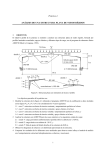
Although mounted·on a single circuit board, an ACTR con-
tains independent receiver and transmitter and receiver subsections.
The complete ACTR assembly is shown in Figures 1-3.
Each data word is sent under program control.
transmission consists of the transfer of
(DG word)
gram use).
~and
2~
A complete
bits; 16 data bits
4 control bits (transmission status bits for pro-
After data bits are strobed into the transmitter
buffers, the data transfer is initiated by setting the Busy flag.
After the transmitter has sent all 20 bits, it clears the Busy
flag.
The transmitter subsection cannot request an interrupt
when it has completed its operation,
Accomp~nying
each trans-
mitted bit is a clock pulse which is used to activate the clocking
cycle of the ACTR receiver in the other system.
When
th~
re-
ception of the incoming word is completed, the receiver sets
the Done flag.
The ACTR receiver is connected to the interrupt
system (i.e. the ACTR receiver can generate an interrupt request)
7
De"S&L
J)~iA.
·
. O~TOB
Ss;f>~,. ION
2.
PUL.~e.
......-.......
Hooe.
'-s Jn~
<.DlltfR.a\. lo-....
~_.-------2
~
DAl~ \2.
~\'l1"P - -
lllA~SMt~R
n~
L~
•
lf
3HIFT
!>Alft
~s 2. J>
TC.P
J)A.T A
L.o-.D
pc..u...se.
(y "
DLP
~11
_s
I - '°
.-------1---------t---t'
R ~
,__,......__ _ _~.... ' S .fl DLP
•b
''
". ~
C.LOCIC. . PtU.-6~
DAT~
..J:...
D~\AIS _.3_.7'+'1SA '
't ti f
I>t\t ~ l't- -....
cl ,
S>A.TA l S - a . t
loo f\5
100
t
l.
.DA1 A;, _ ___,,.
D;t __3-17.,.'\SA
7't-l2.?>
#2.1
-
f2.
DAtAJ..--..
OAlA~_..,.s
TC.P
1'~
,lf Tc.P
--
(.la--
H>
_____<.._.
StA.TP
D~t~
WtDT+\
. 1'
l'UL~E
l.SOns
.
"S
8Jl DLP
Stu.,.-r DATA
~ t---'- -..--
t0
7'\•2.~
TC-f
+s
1'1'>
~.
lo
,fl DLP
~-f
.,___ _ _
' 8.n
A t1
~t~e,
TC.P
~ce.s
to
f l . -¥uc. ...&_ __,.
----.icJ Ot---.
"
t>A1AC\
DA1Alt.
.a 7•P's~·
a+ -ttU.
lf
cl q
Tc.P
~1'-tl
R
'- .
--"-t
10
1,'S
..,.____c._;---- l\ft ~p
+r;
1Z D
• tt z.3
~...1- - - - - . ·
3 Bu~'<
DAT All
'f'~
•s
-M-17
s
CLDCJC.
t>ATA
D~t"~ --~_.irts~
_,.."_
-.04.
COU~TE.~
2.
bu'TGrC>f AiG.
1fl"MsM\~!.toN
LI,_.&.
A"S2.
.,.
DAtAl'f- _ __,.
itl\
t \
tr
T'c.p
Ot\rlt ls--...-...~10
IJ .
Sl~fP
ASYNCHRONOUS COMMUNICATION
TRANSMITTER RECEIVER
Butt.June 3, 1978
Sheet· 1 of 3
ACTR
TRANSMITTER
Figure
1
.
.
8
..
,
Co~1R.Ol
woltD
(4 ins)
J)g~SI
•'t
tt(f-
,,.
)~1115 13
\ l.
\?>
to
<\
J
*'tt
n
12.
2. '
' ..n. (lC.f'
c.'
\\ T~SA lo
l
-lS-
-
leCEPl'to~
•
b'-'ISEL:tf
)
'DA1'1ft
I.
~~
-l'I
'~
l~
"*er
'° ct
:ll<t
3
L3
"'
I
1
12.
',
et ARCP
.a
l
'3.
D~TA
II
WoftD
I~
B11s)
\ lc.Q.
\3 ra.
10
,
#19
13
1
3
+s
2.
$
8
A
7'H2.3
1t-2'l
-~ 1 +
,,. .s
u
•
'
'
c\
.rl.rtcr·
C\
-..
'~' Il.lCP
q
74Q.~
6
bATA
«lct
-~
~s
2.
a
TllAkSM~lO~
t.lN£
S£e.K..
C.LOC.f(
JOO
1
rt.
~
:tfJCOM\N.C.
I\~
.fS
,,.,J
~c,P
-
~
C.Loc.k
sons
~
1'1- IS
Re.c.E.l\JEA_.
.,
-
1'2fJ,
..............
l..
A.
"
l'f-,SA '-
____
..f 5
10
'
~
5
ct
~
l'f.CfSA.
-:I\ IS
'
~
l)OlJe
CL.
,
...
@)
~I'\-
.f-S"
1·$.JtS
@
. 11 1'lq5A ~
~'~-
(Ho
l Ofi\PLcr1ol\l C.Loci<.
•
.
c.\ Jl.~
<\
" 74crs.\ ~
,___ _ _ _ _ _ _ _ _ _ _ _o!-1
_________________'
.___....
~
#25
•
ASYNCHRONOUS COMMUNICATION ·
TRANSMITTER RECEIVER
Desi
ACTR RECEIVER
Figure 2
~ Bl\itt.. June
1976
:a.
.f.S
j
Q ~
D
'i
%NT'-
~Eo<.·
J)f)Nf.
.)
DcNe: d
1•1
.EL
It
..s5Tt."T
R,£N8
s
n
A
X MTit.Cj)
R
'
l!.
't
If>
2
DE'JSEL
~5
be~
CLR
I
C\..R.P
a 2.
•
IU.S'(
<-c.oci.
A
s
). .D
l>A.T~8
l2 I> ~
%NT
~
auiY
.a I *13
....,ct__,
~
' C\it.a
R
A
'
,
lb
__s_.
,...._
/
~.....---
•3
't..n.
ASYNCHRONOUS COMMUNICATION
TRANSMITTER RECEIVER
,..
.lNt? ou.T
;~ 81\ltt. June
Sheet 3 of a·
•'
ACTR DEVICE FLAGS
Figure - 3
'
and can respond to an INTA instruction by returning its
code.
de~ice
When the processor realizes that a new data word is present
in the receiver, the information is strobed into specified ac-.
cumulators under program control.
To allow the processor to
sense the state of the ACTR, it places its Busy and Done flags
on the SELB and SELD lines whenever· it
recogni~es
its device code.
The transmitter buffers are loaded from the I/O bus by
the DATOA {data word) and DATOB (control bits) signals respect"."'
ively.
The transmission of data is controlled by 3 "clocks"
(retriggerable monostables); the Data Separation pulse, the Transmitter Clock pulse and the Data Width pulse.
The Data Separation
pulse, as its name suggests, is used to separate the individual
data bit transmissions; to provide the receiver hardware time
to act on each one.
This pulse is initially triggered by the
STRT signal from the processor.
The STRT signal also sets the
Busy flag (which remains high as long as th-e transmission is
in progress).
It is assumed that when the STRT signal is issued
by the processor, the information to be transmitted is already
in the transmitter buffer.
On the falling edge of the Data Sep-
aration, the Transmitter Clock pulse is triggered.
This pulse
is used to shift the next bit irtto position to be transmitted.
The rising edge of the Transmitter Clock generates the Data Width
...
pulse.
This pulse is ANDed with the datum bit to be sent to
produce a pulse of a specified width.
This pulse is then com-
bined with the clock pulse and placed on the Transmission line.
Figure 4 details the actual pulse that is transmitted. · Due to
11
1·1
i.to µs
µs
bit
. 0.
bit
I
clock
l
··1 •
data
I
clock
data
Times shown are characteristic of a
co- axial
20 ft ..
cable
Negative clock pulse is sent for greater
noise immunity
TRANSMITTgD
Figure
4
PULSE
12
the manner in which the incoming information is clocked into
the receiver buffer, the Data Width must be at least a factor
of two longer than the Transmitter Clock.
The falling edge of the data width pulse increments a
counter network which is responsible Tor terminating the· clocking
cycle at the end of the transmission.
2~,
the Busy flag is clocked over to ~.
When the counter reaches
When Busy is in the
B
state, the Transmitter Clock pulse cannot be generated on the
falling edge of.the Data Separation pulse and the clocking sequence is halted.
The counter is zeroed at the start of each
transmission by the STRT pulse.
The complete sequence for the
trans•itter is outlined in Figure 5.
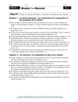
The receiver is activated on the falling edge of the
incoming datum pulse (the negative of the Transmitter clock).
This edge triggers the Data Seek and Reception Completion clocks.
The Data Seek pulse must remain high for more than half the length
of the Data Width of the transmitting ACTR.
The Data Seek is
used to indicate when the actual transmitted datum is incoming
(i.e. when the clocking signal that begins each transmission is
completed).
The falling edge of the Data se·eks generates the
Receiver Clock Pulse which actually shifts the incoming datum
bit into the receiver buffer.
The Reception Completion clock is triggered on every
incoming transmission.
This clock is set to fall in a time that
corresponds to approximately
(1 bit) transmission.
1~
times the period of a complete
Each incoming data transmission will re-
trigger this clock (put the clock cycle back to the beginning)
13
START
BUSY.
DATA
SEPARATION
ULSE
STRETCHER
I1
DATA BIT
TRANSMITTER
Figure
CLOCKING
5
14
r-----r------
'
r--------INCOMING
'
I
'
.I
DATA TRAIN
RECEPTION
COMPLETION
DATA SEEK
RECEIVER
CLOCK
Data clocked into buffers on
negative edge of
RECEIVER CLOCKING
Figure
8
receiver clock
l5
so that the Reception Completion clock will not fall until the
transmission of all 20 bits is completed.
The entire clocking
sequence of the receiver is illustrated in Figure 6.
The clocking times shown in Figures 1 and 2 are representi ti ve of a system with a cable length of 20 feet.
These
times will vary with the length and type of cable used to connect
the two processors.
to start tuning
However, they do give a base point at which
an ACTR pair.
When the Completion clock falls, it clocks the DONE over
to 1.
This condition can be determined by sensing the DONE flag
or through the interrupt,standard on the NOVA (ECLIPSE} line~
Since a reception of data can normally occur at any time, the
normal operating environment for a system using the ACTR would
be with the interrupts enabled, so that the CPU can respond to
a data reception whenever it happens.
In e¥ery instruction cycle, the processor generates RQENB
wh~!h
places the interrupt request signal INTR on the bus from
·a given device (i.e. sets its IHT REQ flip flop) if its Done
flag is set and its Interrupt Disable flag is clear.
Under program
control, the processor will generate the MSKO signal to set up the
Interrupt Disable flags of all devices according to the information. on the data lines (DATA8
=1
to set the ACTR Interrupt
Disable and DATA8 = 0 to clear the ACTR Interrupt Disable,
In
the ACTR interface, the actual flag is a INT ENABLE but it responds
to a generated MSKO instruction as any standard DG interface would).
After an interrupt has been recognized by the processor,
program control will go.to the interrupt handler
speci~ied
in
memory location 2 of the processor.
The interrupt handler can
16
determine which device needs service by sensing Done or it
can
issue INTA to read the device code of the nearest deyice
requesting an interrupt.
When an INTA instruction is executed by the processor,
the INTP IN signal is generated.
The ACTR will receive this signal
only if no INT REQ flip flop is set in a device closer to the
processor on the bus; the INTP must be terminated at the first
device where the INT REQ is set.
A second signal, INTA, is gen-
erated at a time sufficiently long afterwards to ensure that
the INTP signal has been terminated.
The INTA signal is used by
the device, which terminated the INTP, to clock its device code
onto data lines 10-15 of the I/O bus.
This data is strobed into
the processor at the end of the INTA.
The timing of the logic
signals that control the interrupt sequence is outlined in Figure
7.
Once execution of the INTA instruction is completed, the device
code
recei~ed
can be used to vector control to the appropriate
routine to service the interrupt.
The interrupt service routine
the
r.~ceived
~or
the ACTR must strobe
data into the processor by issu:i,ng a DATI'A (data
word) and DATIB (control bits) signal over the I/O Bus.
The
interrupt handler must clear Done by issuing a CLR signal so that
the ACTR will not immediately request
anothe~
interrupt for the
same reception when the interrupt system is turned on and Interrupt
Disable is cleared.
Clearing Done also clears INT REQ, disabling
INTR.
The timing of the various clocks in the ACTR is controlled
by res is tor ( trimpot )- c.·apaci tor pairs •. The clocking systems
17
DS0-5
INPUT
DATIA, DATIB,
OR DATIC
BATA0-15
s:;;'.)BE DATA
l~V: t.C
smr. CLR,
OR IOPLS ·
(IF PRESENT!
050 - 5
~ 500 Mill
~ATI
150 ..---------.
350 MIN
I
rmNj
_J
L FROM
MAXIMUM TIME
1100 . . - - - - - - - - - - .
LEADING EDGE
:]
f
f
i
l
l
. _ - - - - - - - - - - - - - O F STRT,CLR AND
1
150
rwq
DS0-5
{ SELB,SELO
TO STATE
. IOPLS
CHANGE IN SELB,
I
350 MIN
I . 350 MIN
STRT, CLR,
OR IOPLS
(IF PRESENT)
SKlP
TIMING FOR INTA
ANO MSKO IS THE
SAME AS FOR
INPUT ANO OUTPUT
RESPECTIVELY
200 MAX
GATES DATA
ONTO BUS
OATA0-15
OATOA, OATOB,
150
OR DATOC
_ _...._Q.il fl_M_IN_,
OUTPUT
L
_J
SELD AND INTR IS
. 250 NS
_
150MAX
DS0-5 GATE BUSY, DONE ONTO SELB, SELD LINES
PROGRAMMED TRANSFERS (IN-OUT INSTRUCTIONS)
'<
- - - - 1 5 0 MIN----1
ROENB
.
DEVICE DONE
DEVICE'
INT DISABLE
INTR
INTP IN
INTP OUT
INTA
OATA0-15
DS0-5
r--
--.. .~-------~~-'---------4~
500 MIN
200 MAX
COOEOF THIS
--..-------11---------ti--DEVICE
-----~--~\--------n-------~
CLR
I
DEVICE NOT DONENO INTERRUPT
REQUESTED
I
DEVICE SETS DONE
ANO REQUESTS
INTERRUPT
CODE OF THIS
DEVICE
PROGRAM GETS CODE · 1 PROGRAM CLEARS ·
OF NEAREST DEVICE
DONE AND INT REO
.
I REQUESTING INTERRUPT
PROGRAM INTf~PT
TIMtMe.
Figure 7
18
in the two connected ACTR interfaces must be tuned to one another
by adjusting the appropriate trimpots so as to obtain the maximum data transfer rate
possible~
given the characteristics of the
connecting transmission lines and the latency of the interface.
elements.
The next chapter will deal with the software aspects of
data transfer with the ACTR.
The I/O structure of the NOVA (ECLIPSE)
minicomputers will be reviewed with special attention to the program control of ACTR.
..
CHAPTER 3
PROGRAMMLHG THE ACTR
The software control of the ACTR is very straight forward but to be able to use this device effect{vely, the I/O handling
facilities of the NOVA (ECLIPSE) must be well understood.
chapter will be devoted to
~
This
detailed description of the pro-
gramming concepts of the I/O system with specific references
to the handling of the ACTR.
In order for the processor to perform useful vork for
the user 9 there must be some method for the program to transfer
information outside the machine.
set provides this facility.
The Input/Output (I/O) instruction
There are eight I/0 instructions
which allow the program to communicate with I/O devices, control
the I/O interrupt system, control certain processor options and
to perform certain processor functions.
The NOVA (ECLIPSE) line bas a 6-bit device selection
network, corresponding to bits l~-15 in the I/O instruction format.
Each device is connected to this network in such a way that it
will only respond to commands with its ovn device code.
Each
device also has two flags, Busy and Done, which control its
operation.
In conventional DG
devices~
when Busy and Done are
both zero, the device is idle and cannot perform any operations.
To start a device, the program must set Busy to 1 and set Done
to 0.
When a device has finished its operation, it sets Busy to
0 and Done to 1.
The ACTR, being essentially two devices in one
19
20
0
0
I
1
I OP
AC
I
1
2
3
4
5
I
COJ?E
6
7
EONj'ROII
8
9
t
INSTRUCl'ION FORMAT
Figure 8
I
I
10
11
•
1/0
CODE
DEVICE
12
I
13 . 14
us
21
{transmitter and receiver), does not confora to the standard
DG flag configuration.
flag must be set.
To begin a transmission, the ACTR Busy
When the
will clear the Busy flag.
is completed, the ACTR
t~ansmission
When a reception is completed, the
ACTR sets its Done flag.
The format for the I/O instruction~ is illustrated in
Bits ~-2 are p11, bits 3-4 specify the accumulator,
Figure 8.
bits
5~7
contain the operation code, bits 8-9 control the Busy
and Done flags in the device, and bits 10-15 specify the code
of the device.
The six bits provided for the device code in the
I/O format mean that 64 unique device codes are available for
use.
Some of these device codes, however, are reserved for the
CPU and certain processor options.
Most of the remaining codes
have been assigned to :particular device by De.ta General.
device code normally chosen for the ACTR is
4¢°a •
The
In standard
DG hardware, this corresponds to a Synchronous Communication
Receiver (SCR), a device which will not be used on a system with·
an ACTR.
In order to operate the ACTR transmitter, the program
must first ensure that the device is not currently performing
some operation.
% state
This is done by testing the Busy flag for a
by
SKPBZ
JMP. -1
ACTR
. rs'" BUSY ZERO?
'
;NO ••• CONTINUE CHECKING
;ACTR NOT BUSY
Next the control and data words must be loaded into the transmitter
buffer.
The control bits can be used to inform the receiving
22
computer of the nature or the data transfer. (i.e. start of message, end of message, data
a~knowledgement
etc.). After loading
the data into the interface, a staJ;"t pulse must be sent to the
hardware to begin the actual transmission (set Busy to 1).
DOA ACS
DOB ACD
IHOS
'
,
ACTR
ACTR
ACTR
.,
., LOAD
DATA
ACTR BUFFER A WITH
FROM ACS
; LOAD ACTR BUFFER B WITH
; CONTROL BITS FROM ACD
, NO I/O TRANSFER
; -S- SETS BUSY TO 1 TO
, BEGIN TRANSMISSION
.
.
Since the start pulse can be issued as soon as the hardware buf'f'ers
are loaded, this group of' instructions can be shortened to
DOA ACS , ACTR
DOBS ACD, ACTR
Once the datum has been sent, the transmitter subsection
of' t·he ACTR has no way of knowing whether the other computer has
received it and strobed the data into the processor (i.e. it is
ready to accept more data). It is therefore advisable to have
the receiving computer send a data acknowledgement message using
its own transmitter.
When a transmission is received, the Actr Done is set
to 1. The method or ascertaining this condition will be dealt
with in some length shortly but f'or now let us assume that we
know that a reception has been completed. The A buffer of' the
receiver (d~ta word) must be loaded into an accumulator as well
as the B buffer (control bits). The Done f'lag
to 0 by a clear pulse:
ai so
1
must be put
23
DIA
ACS, ACTH
DIBC ACD, ACTR
;READ DATA WORD INTO ACS
;READ CONTROL BITS INTO ACD
;CLEAR ACTR DONE FLAG
Once the ACTR has completed the reception of a word (20
bits), it sets Done to 1.
The program can determine this con-
dition in one of. two ways.
By using the I/O SKP instruction,
the program can test the condition of the Done flag.
SKPDN ACTR
;IS DONE l?
JMP • -1
;NO ••• CONTINUE TO WAIT
;YES ••• MESSAGE RECEIVED
Another way is to utilize the interrupt system that is standard
on the NOVA {ECLIPSE) computer.
The interrupt system is made
up of an interrupt request line to which each I/O device is
con~
nected, an Interrupt On flag in the CPU, and a 16-bit interrupt
priority mask.
The Interrupt On flag controls the status of the
interrupt system.
If the flag is set to 1, the CPU will respond
to and process interrupts.
If the flag is set to ¢, the CPU
will not respond to any interrupts.
An interrupt request is
initiated by an I/O device when it completes its operation.
When
the ACTR completes a message reception, as well as setting Done,
it also places an interrupt request on the interrupt request line,
provided that the bit in the interrupt priority mask {bit 8)
which corresponds to the priority level of the device is
the mask bit is 1, the ACTR can set its Done
~o
p.
If
l, but does not
place an interrupt request on the interrupt request line.
If the Interrupt On .flag is 1 at the time. the processor
completes execution of any instruction, the processor honours
any requests on the interrupt request line.
If the Interrupt
On flag is O, the CPU does not look at the interrupt request
line, it just continues to the next sequential instruction. The
CPU honours an interrupt request by setting the Interrupt On
flag to 0 so that no interrupts can interrupt the first part
of the interrupt service routine. The CPU then pla.ces the updated program counter into physical memory location 0 and executes
a "JMP @l" instruction. It is assumed that physical location
1 contains the address, either direct or indirect, of the interrupt service routine.
Once the CPU has transferred control to the interrupt
service routine, it is up to that routine to save any accumulators
that will be used, save the carry bit if it will be used, determine which device requested the interrupt, and then service the
interrupt. The determination of which device needs service can
be done by I/O SKP instructions or the routine can use the
INTERRUPT ACKNOWLEDGE instruction.
The INTERRUPT ACKNOWLEDGE instruction (INTA) returns the
6-bit code of the device requesting the interrupt. If more than
one device is requesting service, the code returned is the code
of that device requesting an interrupt which is physically closest
to the CPU on the I/O bus. After servicing the device, the interrupt routine should restore all saved
value~~
..
set the Interrupt
On flag to 1 and return to the interrupted program. The instruction
that sets the Interrupt On flag to l
(Interrupt Enable) allows
the processor to execute one more instruction (if the Interrupt
Enable instruction changed the condition of the Interrupt On
flag) bef'ore the next interrupt can take place .. In orde·r to
prevent the interrupt service routine from locking itself inta
25
a loop, this next instruction should be the instruction that
returns control to the interrupted program.
Since the updated
value of the program counter was placed in location I
by
the
CPU before honouring the interrupt, all the interrupt routine
has to do, after restoring the AC's and the carry bit, is to
execute an INTERRUPT ENABLE instruction and a "JMP @ %" instruction
and control will be returned to the interrupted program.
If the Interrupt On flag remains O throughout the interrupt
service routine, the interrupt routine cannot be interrupted and
there is only 1 level of device priority.
This level is deter-
mined by either the order in which the I/O SKP instructions are
issued or (if the INTERRUPT ACKNOWLEDGE is used) by the physical
location of the devices on the bus.
In systems of videly differing
speeds, such as a teletypewriter versus a fixed head disc, the
programmer may wish to set up a multiple level interrupt scheme.
Hardware and instructions are available on the NOVA (ECLIPSE)
computers to allow the implementation of priority interrupts.·
Each of the I/O devices is connected to a bit in the 16
bit priority mask.
Devices which operate at roughly the same
apeed are connected to the same bit in the mask.
standard~mask
Even though
bit assignments have }ligher number bits assigned
to low speed devices, no implicit ordering is intended.
~
The
manner in which these priority levels are ordered is completely
up to the programmer.
The condition of the priority mask is altered by the
MASK OUT instruction.
Ir a bit in the priority mask is set to 1,
then all devices in the priority level corresponding to that
r
bit will be prevented from requesting on interrupt when they
complete. aa operation.
from devices in
t~at
In addition all pending interrupt requests
priority level are disabled.
The priority
mask bit for the ACTR is bit 8.
If the receiving computer has many calculations to perform, it cannot handle an incoming ACTR transmission by continually testing the state of the Done.
It is necessary then to
use the interrupt system to allow the processor to do other computing between interrupts and only reference the ACTR when it
has received a complete transmission.
This scheme also allows
the processor to recognize data transmission as soon as it is
received rather than periodically checking the ACTR for a new
mess.age.
Use is made of the priority level interrupt scheme in
operating systems such as Data General RDOS (Real Time Disc
<'~
Operating System) and RTOS (Real Time Operating System).
These·
systems supply a multi-priority level interrupt handler.
Devices
are included in this handler either at system gederation or during
run-time.
When an··,'interrupt is detected by. the. hardware, the
currently executing program
interrupt dispatch program.
i~
suspended and control goes to an
This routine. directs contr·o1 to the
correct servicing routine by using the
devi~e
code (obtained
by an INTA instruction) as an index into an interrupt branch
table.
The entry in this table is the address of a device control
table (DCT) associated with the device
servic~
routine.
This
table contains the service mask that is to be ORed with.the current
27
interrupt mask while control is in the device service routine.
This mask establishes whick devices if any will be allowed to
interrupt the currently interrupting device. Since interrupts
are enabled when control is passed to a device service routine,
the interrupt service mask must contain the mask bit for the
device being serviced.
The handling of the ACTR through the facilities of RDOS/
RTOS relieves the programmer of the responsi bili ti es ·o:r maint ainig
program continuity during interrupts and implementing a multile~el
interrupt handler. RDOS/RTOS is very useful in handling
two pr6blems which arise as a result of design constraints
of the ACTR.
IN a multi-tasking environment, there will be competition
for system resources (the ACTR among many others). A task currently using the ACTR must be assured that no other routine will
also attempt to initiate a data transfer. The RDOS/RTOS facility
of sync words in a multi-tasking environment allows a routine
to gain exclusive control of the ACTR hardware and software and
maintain control until it has finished its transmission and any
accompanying receptions. ACTR control would always be allocated
on a priority basis and any requests for the ACTR, th~~ are issued
while it is in use, would be queued until the ACTR became free •
•
When using the ACTR, the transmitting computer must await
an acknowledgement of reception before sending more data. If
both systems in the ACTR begin to transmit simultaneously, data
could easily be lost when the ACTR receiver routines mistake
incoming data for an acknowledgement of the data it has sent.
28
The user must design the ACTR handlers to be able to accommodate
an occur.ence of this kind or so design the system configuration
to eliminate the possibility of the two CPU's attempting to transmit
simultaneousJ.y.
In a master-slave environment, the competition for the
AC'.l'R hardware between systems can never occur.
In this mode, the
master computer would always initiate communication between the
two processors.
The slave system would only transmit ·to fulfill
requests from the master.
The task facilities of RDOS/RTOS allows
one task to be dedicated to servicing the ACTR in the slave CPU.
This task would gain CPU control only when the ACTR receiver
generates an interrupt.
Once the message reception is completed,
this task would determine what further action has to be taken.
Appendix A of this report will deal with the implementation
of a softvarechandler for the ACTR in a multi-tasking environment
for a master/slave system.
•
29
ACTR COMMAND
DIA
DIB
DOA
DOB
NIO
SKP
t
<r>
<r>
<r>
(f)
(f
>
(t)
ac,
ac,
ac,
ac,
ACTR
ACTR
ACTR
ACTR
ACTR
ACTR
read receiver control bits
read receiver data word
send data word to transmitter
send control bits to transmitter
no I/O transfer
skip if(t)is true
BN
tests
tests
tests
tests
BZ
DN
DZ
f
c
for
for
for
for
Busy
Busy
Done
Done
=
=
=
=
1
0
1
0
will clear Done and clear ACTR
interrupt request
will set Busy and begin
transmission
s
CENTRAL PROCESSOR FUNCTIONS
INTA
ac
vill return 4~ to specified accumulator if the ACTR
is the nearest device to the processor requesting
an interrupt
MSKO
ac
will prevent the ACTR from generating an interrupt
if bit 8 is set in the specified accumulator.
IORST
will clear the Done and Busy of the ACTR and the
Interrupt Disable ~lag {equivalent of a MSKO with
8--= 11). The I_nterrupt Request of the ACTR will
al.so be cleared.
ACTR CONTROL SUMMARY
Figure 9
30
In summary, the control logic for the ACTR arises quite
logically out of the DG I/O structure.
A small number Of I/o
commands allow complete control of the ACTR and its link into
the interrupt structure and the general control store of the
central processor.
instructions that
Figure 9 contains a brief resume or· the dedicated
~ontrol
the ACTR and the central processor
that influence the ACTR as part of their general operation.
fun~tions
CHAPTER 4
CONCLUSIONS
The transfer of usable information betveen any computer
systems is always a complex undertaking: the information must
be put into a format that the other processor can accept and act
on, the integrity of the transferred information must be ensured,
synchronization of the systems must be accomplished so that data
is not lost betveen the systems and data must be moved between
the machines as quickly as possible.
The ACTR can fulfill the above requirements vhen used in
the proper operating environment.
The ACTR master/slave handler
will transmit messages formatted by the user and perform parity
checking on all received information.
Since data is completely
assembled in the ACTR receiver before it is read in and data
~
acknowledgements are necessary, processor-processor synchronization
is not a problem.
The slower speed of the ACTR, when compared
with the MCA is out-weighed in many applications by its increased
range and error checking capabilities.
The reliability of the
ACTR hardwate is such that its transfer rate can be safely increased
by the
~limination
of all error checking.
(~he
user. should however,
use the ACTR diagnostic in APPENDIX B to ensure that the hardware
transfer clocks are not marginally adjusted.)
Minicomputer multiprocessor systems, such aa those based
on Data General lIOVA and ECLIPSE processors, represent one of
the most rapidly growing areas in computer development.
31
Their
32
inherent versatility and sizable computer pover make them an ideal
medium for real-time instrumentation control and simulation systems.
With the reliance these systems place on shared processor
resources~
data transfer devices such as the ACTR will continue to be an
important system compound.
APPEMDIX A
ACTR MASTER-SLAVE HANDLING ROUTINES
An important function of any real time operating system
is the efficient handling of input-output operations.
Optimum
usage of machine devices and central processor time in the ac. complishment of tasks is the real reason for designing and implementing
a multi-tasking system.
The responsibility of RDOS/RTOS I/O control is to react
during normal program execution to the
quests, making
assignment~of
structurin~
of I/O re-
requests to machine devices when
they are idle, and queuing requests for devices which are-busy.
Through the queuing facility, RDOS/RTOS makes it possible to achieve
maximum and continuous overlap of multi-tasks without direct
intervention by the tasks themselves.
The handler tor the ACTR
in the master-slave environment conforms to these requirements,
enabling tasks to access the ACTR with minimal pre-processing.
The handler for the ACTR is composed of three sections:
a transmission routine (SENDM)~ a reception routine (RECM) and.
an identification and interrupt routine {IDACTR).
These routines
exist, with only minor differences, in both the master and slave
processor.
The call to the routine SENDM is similar in structure
to a RDOS/RTOS SYSTEM call as it incorporates both an error and
normal return.
Control of SENDM is allocated on a priority basis
to calling tasks through use of the RDOS/RTOS facility of sync
33
34
f1
DESTINATION
WORD COUNT
MESSAGE #
(ACTUAL MES.SAGE)
ACTR MASTER-SLAVE MESSAGE FORMAT
·Figure 1¢
35
words.
Once a task gains control of SENDM through a sync word,
it maintains exclusive control until all data transmissions requested by that task are completed.
A calling task passed SENDM the address of the message
to be transmitted.
This message must be constructed in accord
with the format illustrated in Figure IO.
The actual message
transmitted begins with the word count; the first two words are
for the use of SENDM only and are not included in the word count.
The control bits, which accompany
eac~
transmitted data word,
are used to indicate the start of a transmission, erid of transmission and the parity of the transmitted data.
The control
bits are generated by SENDM and are not passed beyond the ACTR
routines.
After each data.word is transmitted, the SENDM routine
goes into task suspension aw.aiting the reception of the data
acknowledgement from the receiving computer.
Once the reception
acknowledgement is received, it is checked for a data error message.
If a data.error is confirmed, the transmission is terminated,
ACTR control is released and the error return is taken from SENDM.
If a task in the master CPU, that calls SENDM expects
a return message from the slave CPU, the DESTINATION word in the
message that it passes to SENDM must contain the address for the
reception of the incoming data.
word must be set to -1.
When
If no return is expected, this
SE~D~
has completed transmitting
its message, the DESTINATION is checked for a valid address.
If it is found, control is passed. to RECM, the reception handler,
otherwise the control of SENDM is released to the.system and the
normal return is taken back to the calling task.
The reception routine, RECM, is not directly accessible
to the user.
It is called by SENDM in the master CPU if a return
message is expected from the slave CPU.
In the slave CPU, RECM
is part of the reception task (ACTR} which is r.esponsible for all
receptions and transmission in that processor.
RECM awaits each i_ncoming data transmission by a REC
to a sync word.
This sync word is activated by an IXMT from the
ACTR interrupt handler upon the reception of data into the re- .
ceiver buffers.
Once RECM is unsuspended, a parity check is
performed on the incoming data.
If a parity error is detected
in the received words, an error message is returned to the transmitting
compu~er
in tl1:e data acknowledgement.
If no ·error is
detected, the received data is stored, and a successful reception
is signalled.
In the master CPU, the core area for the reception of
data from the slave is contained in the DESTINATION word of the
message that initiated the response from the slave.
Once the
entire message is received, control of the ACTR is returned to
the system and the normal return is taken from SEDDM.
In the
event of a re-c'eption error, ACTR control is relinquished and
the error return is taken.
The slave CPU
~ses
RECM as part of the ACTR service task.
The system initializer is responsible for tasking off this monitoring task {entry point ACTR}.
is allowed any access to the ACTR.
No other task in the slave CPU
The slav• uses the received
message number to determine the core area that
is
to be used to
37
store the incoming transmission.
This message number also de-
termines which subroutine is to be called to handle the message
after it has been completely assembled in the core.
After control
is returned from this post-reception processing, the ACTR task
awaits the next message.
The message handling routines called from RECM in the
slave CPU may call SENDM to return a message to the master com•
puter or introduce changes in the control functions of the slave
CPU.
The action taken by these called handlers is left completely
up to the user.
For the ACTR handlers, RECM and SENDM, to operate properly,
it is necessary that an interrupt handler for the ACTR be included
in the interrupt dispatch table of RTOS/RDOS.
This can be done
either at SYSGEN or during the execution program.
Any device
that issues an interrupt that:'.1s not included in the dispatch
table will have its interrupt cleared with a resulting loss of
information.
The routine IDACTR links the ACTR interrupt handler (IACTR)
·into the RTOS/RDOS interrupt structure through use of a run-time
system. call.
to the system.
It then releases control of the SENDM sync word
By locking out SENDM until the device identification
is completed, the users of the ACTR are assur.,ed that no information
will be lost during system initialization.
As was mentioned before, SENDM and RECM vary slightly
between the master and slave computers.
Through use·or the cap-
abilities of the DG MACRO Assembler, one source file can be made
to include both the master and slave versions.
The assembly of
38
the respective relocatable binary files is controlled by an equate
switch (MASTER).
When the switch MASTER= 1, the master CPU
version is assembled and when MASTER
erated.
= 0,
the slave code is gen-
This switch must be defined in an equate :file which
proceeds the ACTR handler source :file (INTERLINK) in the ~AC
string.
.The version of the ACTR handler presented in this
is that •ppropriate to the slave CPU.
Appendi~
Those parts o:f the source
:file that appl.ied only to the master computer are.'.listed but
have not generated any code.
0001 LINK
01
02
09:21:06 02/27/77
MACRO REV 04.00
39
03
04
05
06
07
08
09
10
11
12
13
15
16
17
18
19
20
21
22
23
'
.·******************************************************
'
; 01 TITLE
.TITL LINK
; ACTR. HANDLER
.'
.,·********.*********************************************:
'
; 02 IDENTIFICATION
.'
.
.'' NAME: INTERLINK.SR·
.
PURPOSE:
24
'
25
.;'
.,,•
.,
.,
.,
AUTHOR:
26
27
28
29
30
31
32
33
,..
THIS PROGRAM SUPPLIES TRANSMISSION ANO
RECEPTION ROUTINES FOR THE ACTR
MICHAEL BRETT
OR:{:GINAL ISSUE DATE:
ISSUE:
1/2/77
1
DATE OF ISSUE:
1/2/77
,·******************************************************~
•
!0002 LINK
40
01
02
03
04
05
06
07
08
09
10
11
12
13
14
15
16
17
18.
. 19
20
21
22
23
24
25
26
27
28
29
30
31
32
33
. 34
35
36
37
38
39
40
41
42
43
44
45
46
.,,
.,;
·******************************************************~
03 DESCRIPTION
.,;
NARRATIVE:
.,
.
.,
.;,
..,
.,
.,
..,
.,,
..,
,
.;,
.,
.,
.,
.,
.
.,
.
.,
.,
.,;
.
.,
.,
.
.,
THIS ROUTINE IS A SOFTWARE INTERFACE TO THE ACTR.
IT OPERATES IN A MASTER/SLAVE ENVIROMENT WITH THE
MASTER CPU INITIATING ALL DATA TRANSFERS •
MESSAGE FORMAT IS
I
I
I
I
I
I
0
DESTINATION
·WORD COUNT
MESSAGE f
(ACTUAL MESSAGE)
WORD COUNT DOES NOT INCLUDE LEADING 0 OR
DESTINATION. MESSAGE # CORRESPONDS TO A TABLE ENTRY
IN SLAVE CPU, IGNORED IN RECEPTION IN MODEL •
DESTINATION IN MODEL IS -1 IF NO RETURN MESSAGE
IS EXPECTED; CONTAINS RECEPTION ADDRESS IF
RETURN IS EXPECTED; IGNORED IN THE SLAVE •
FIRST 2 WORDS OF MESSAGE ARE NOT TRANSMITTED.
WHEN SENDM IS CALLED, AC2 MUST CONTAIN A
POINTER TO THE START OF THE MESSAGE. AN STX IS
SENT WITH THE WORD COUNT AND AN ETX WITH THE
LAST WORD. THE RECEIVING. COMPUTER WILL PERFORM
A PARITY CHECK ON THE INCOMING DATA. IF AN
ERROR IS DETECTED, IT WILL SEND AN ERROR MESSAGE
IN THE DATA ACKNOWLEDGEMENT. IF SENDM RECEIVES
AN ERROR MESSAGE NO FURTHER TRANSFERS WILL BE
ATTEMPTED AND THE ERROR EXIT WILL BE TAKEN •
IDACTR WILL IDEF THE ACTR TO RTOS/RDOS
AND RELEASE THE SENDM SYNC WORD SO THAT SENDM
CAN BE ACCESSED.
THE SLAVE CPU RECEPTION TASK (.ACTR) WILL
USE THE MESSAGE # TO FIND THE RECEPTION AREA
FROM AN EXTERNAL TABLE (TABLE) AND TO FIND
THE HANDLING ROUTINE FOR THE MESSAGE FROM
ANOTHER EXTERNAL TABLE (H~DLR) • • ACTR MUST
BE TASKED OFF DURING SYSTEM INITIALIZATION •
,·*******************************************************
.41
!0003 LINK
01
02
03
04
05
06
07
08
09
10
11
12
13
14
15
16
17
18
19
20
21
22
23
24
25
26
27
28
29
30
31
32
33
,·*******************************************************
.
,.
; 04 CALLING SEQUENCE
..,
;
.,,
.,;
.,
..'
.,
,
'
"""""""'SENDM"" ........
AC2: START OF MESSAGE HEADER
CALL: JSR @.tl
SENDM
ERROR RETURN
NORMAL RETURN
RETURN: NONE
ALL ACCUMULATORS AND CARRY
DESTROYED
.;
..,
.,'
.,
"'""""IDACTR ........
NO ACCUMULATORS PASSED
CALL: JSR @.+l
IDACTR
RETURN: NONE
ALL ACCUMULATORS AND CARRY
DESTROYED
;
;
;
........... ACTR""'"'"'
CREATED AS ACTR RECEPTION TASK
IN SLAVE CPU
I
.,
,·*******************************************************
!0004 LINK
01
02
03
04
05
06
07
08
09
10
11
12
13
42
·******************************************************
I
05 SUBROUTINES
;
;
;
;
;
THE LINK STRING MUST INCLUDE A FILE WHICH
DEFINES THE PARAMETER MASTER. MASTER=l
FOR A MASTER CPU COMPILE AND MASTER=0
FOR A SLAVE CPU COMPILE.
THIS EQUATE MUST APPEAR FIRST IN MAC STRING
.,
14
,
·******************************************************
15
;
16
17
18
19
20
21
22
23
24
25
.;
26
27
28
29
30
31
32
33
34
35
36
37
38
39
40
41
42
06 EXTERNAL DATA
I
.EXTN .IXMT
.EXTN .XMT
.EXTN .REC
.EXTN .UIEX
000001 .IFE MASTER
.EXTD HNDLR
.EXTD TABLE
.ENDC
;
;
;
;
;
;
;
RDOS/RTOS TASK CALL
RDOS/RTOS TASK CALL
RDOS/RTOS TASK CALL
RDOS/RTOS TASK CALL
SLAVE COMPUTER
LOCATION OF HANDLER TABLE
LOCATION OF RECEPTION
.
.,,·*****************************************************
.
I
.;
07 PROGRAM
I
;
000040 .DUSR ACTR=40
006401 .DEUR EJSR=6401
.
I
.ENT IDACTR
.ENT SENDM
000001 .IFE MASTER
.ENT .ACTR
.ENDC
.'
.NREL
; PAGE 1 RELOCATABLE
IACTR:
.,
.,
...,,
STA 2,AC2
STA 3,AC3
DIA l,ACTR:
STA l,RCONT
DIBC l,ACTR
STA l,RDATA
ADC 1,1
• IXMT
HALT
LOA 2,AC2
·LOA 3,AC3
.UIEX
0
0
AREA
377
IAC'I'R
• BLK 8.
.,,
.,
.,
.;,
..
.,
I
;
.,,
.,
;
?\C.,2 STORAGE
AC3 STORAGE
., COMPATIBILTITY
WITH RTOS
INTERRUPT SERVICE MASK
, INTERRUPT SERVICE POINTER
RTOS SAVE.AREA
..
;
I
!0006 LINK
01
02
03
04
05
06
07
08
;
44
;
AC2: MESSAGE ADDRESS
;CALL: JSR @.+l
;
SENDM
;
(ERROR RETURN)
;
(NORMAL RETURN)
;RETURN:NO MESSAGES RETURNED
;
ALL ACCUMULATORS AND CARRY
;
DESTROYED
09
10
11
12
13
14
15
16
17
18
19
20
21
22
23
24
25
26
27
28
29
30
31
32
33
34
35
36
37
38
39
40
41.
42
43
44
45
46
47
48
49
50
51
52
53
54
55
56
,,....,
ACTR TRANSMISSION ROUTINE
SENDM:
00047'055000
00050'020465
00051'077777
00052'050460
00053'151400
00054"151400
00055'050464
00056'025000
00057'044466
00060'014465
00061'030456
STA 3, 0, 2·
LOA 0,SSEND
.REC
STA 2,HEAD
INC 2,2
INC 2,2
STA 2,DATPTR
LOA 1,0,2
STA l,WC
DSZ WC
LOA 2,STX
00062'034457 LOOP:
00063'035400
00064'076040
LOA 3,DATPTR
LOA 3,0,3
DOB 3,ACTR
00065'102400
00066'151004
00067 'HH400
SUB 0,0
MOV 2,2,SZR
INC 0,0
00070'175122
00071"101400
00072'175004
00073'000775
00074'024453
00075 'HH222
00076'133000
MOVZL 3,3,SZC
INC 0,0
MOV 3,3,SZR
JMP .-3
LOA 1,.14
MOVZR 0,0,SZC
ADD 1,2
00077'071140
DOAS 2,ACTR
00100'020433
LOA 0,TRANSM
00101'000051'
.REC
LOA
l,RCONT
00102'024441
00103'125004
MOV 1,1,SZR
00104'000422
JMP FLOP
LOA l,ETX
00105'024433
00106'147414
AND# 2,1,SZR
000000 .IFN MASTER
J~1P IFBACK
.ENDC
000001 .IFE MASTER
00107'000407
JMP NEXIT
;
;
;
;
.,
SAVE RETURN ADDRESS IN HEADER
SENDM SYNC ADDRESS
CAPTURE ACTR CONTROL
SAVE ADDRESS OF MESSAGE
;
;
;
;
POINT AC2 PAST HEADER WORDS
STORE IN TRANSMISSION POINTER
GET WORD COUNT
SAVE IT
REALLY NEED WC-1
; GET START CONTROL BITS
;
;
;
;
GET
GET
PUT
NOW
DATA ADDRESS
ACTUAL DATA
IN TRANSMITTER BUFFER
DETERMINE PARITY
;
;
;
;
;
;
;
;
;
;
;
;
;
;
IS CONTROL WORD NON-ZERO ?
YES ••• INC PARITY COUNTER
NOW DO DATA WORD
IS SHIFTED BIT SET ?
YES •• INC PARITY COUNTER
FINISHED DATA WORD ?
NO •• CONTINUE IN LOOP
GET PARITY ON BITS
ODD # OF BITS SET ?
YES ••• PUT ODD PARITY BITS
INTO CONTROL WORD
PUT IN TRANSMITTER BUFFER
START TRANSMISSION
WAIT. FOR AC~NOWLEDGEMENT
;
;
;
;
;
;
;
;
GET CONTROL BITS
IS IT NON-ZERO ?
YES ••• TRANSMISSION ERROR
GET END OF TRANSMISION BITS
WAS END OF MESSAGE SENT ?
MASTER CPU
YES ••. CHECK IF MESSAGE
IS TO RETURNED
;
;
;
;
SLAVE CPU
TAKE NORMAL EXIT
NO RETURN MESSAGES
IN SLAVE CPU
..
!0007 LINK
01
02
03 00110'152400
SUB 2,2
04 00111'014434
DSZ WC
05 00112'000402
JMP .+2
06 00113'030425
LDA 2,ETX
07 00114'010425
ISZ DATPTR
08 00115'000745
JMP LOOP
09
10
11
12
13
000000 .IFN MASTER
14
IFBACK: LOA 2,HEAD
15
16
LOA 2,1,2
COMi 2,2SNR
17
18
JMP NEXIT
19
JMP RECM
20
21
.ENDC
22
23
24
25
45
DIDN'T SEND LAST WORD
NORMAL CONTROL BITS
; DECREMENT WORD COUNT
; NOT AT ZERO
; AT ZERO •• GET ETX BITS
INCREMENT STORAGE POINTER
SEND NEXT WORD
;
;
;
;
;
;
;
;
MASTER CPU
MESSAGE RETURN CHECK
GET START OF MESSAGE
GET DESTINATION ADDRESS
IS IT -1 ?
YES •• NO RETURN EXPECTED
NO •• RECEIVE MESSAGE
AC2=RECEPTION AREA
00116'024426 NEXIT:· LDA 1,.3
00117'032413
LDA 2,@HEAD
00120'133000
ADD 1,2
;
;
;
;
SETUP FOR NORMAL RETURN
AC3=3
GET RETURN ADDRESS
BUMP BY 3 FOR NORMAL RETURN
00121'020414 EXIT:
00122'126000
00123'000010'
00124'063077
00125'001000
LOA 0,SSEND
ADC 1,1
.XMT
HALT
JMP 0,2
;
;
:
;
;
;
SENDM EXIT
GET ADDRESS OF SENDM SYNC
MAKE ACl NON-ZERO
RELEASE SENDM CONTROL
SYSTEM ERROR!!!
RETURN TO CALL
00126'032404 FLOP:
00127'151400
00130'151400
00131'000770
LOA
INC
INC
JMP
26
27
28
29
30
31
32
33
34
35
36
37
38
35)
40
41
42
43
44
45
46
\
2,@HEAD
2,2
2,2
EXIT
~ SETUP FOR ERROR EXIT
; GET MESSAGE ADDRESS
; BUMP BY 2 FOR ERROR RETURN
.,
; LEAVE SENDM
46
!0008 LINK
01
02
03
04
05
06
07
CONTROL WORDS FOR ACTR ROUTINES
08
09
10
11
12
13
14
15
16
17
18
00132'000000 HEAD:
00133'000134'TRANS:
00134'000000
00135'000136'SSEND:
00136'000000
0
.+l
0
.+1
0
00137'000001 STX:
1
00140'000002 ETX:
2
00141"000000 DATPTR: 0
19
20
21
22
23
24
25
26
27
28
29
\
\
.' START OF MESSAGE
.' TRANSMISSION COMPLETED
.' SENDM CONTROL SYNC
..' STX
CONTROL BIT
ETX CONTROL BIT
'
; MESSAGE POINTER
.
00142'000000 RDATA:
00143'000000 RCONT:
0
0
.'' RECEIVED
RECEIVED
00144'000003 . 3:
00145'000000 WC:
3
.' WORD
00146'000040 .40:
00147'000014 .14:
ACTR
14
0
DATA WORD
CONTROL WORD
COUNT
DEV CODE OF ACTR
PARITY INDICATORS
SYNC
47
!0009 LINK
01
02
03
04
000001 .!FE MASTER
05
06 00150'006401 .ACTR: EJSR IDACTR
000000·
07
08
AC~R ~O
I
I
09
.ENDC
10
11
12
13
14
LDA 0,TRANS
15 00152'020761 RECM:
16 00153'000101·
.REC
JSR PARITY
17 00154'004451
LDA 0,STX
18 00155'020762
LDA l,RCONT
19 00156'024765
20 00157'107415
AND# 0,1,SNR
21 00160'000422
JMP AHEAD
000000 .IFN MASTER
22
LDA 1, RDATA'
23
24
STA 1,WC
25
.ENDC
26
000001 .IFE MASTER
27
28
29
LOA 2,RDATA
30 00161'030761
ADCZL 3,3
31 00162'176120
ADD 3,2
32 00163'173000
STA 2,WC
33 00164'050761
34
35
LOA 0,TRANS
36 00165'020746
37 00166'000153'
.REC
JSR Pl\RITY
38 00167'004436
39
LOA 3,RDATA
40 00170'034752
41 00171'030002$
LOA 2,TABLE
ADD 3,2
42 00172'173000
LOA 2,0,2
43 00173'031000
44
LOA l,HNDLR
45 00174'024001$
00175'137000
ADD
1,3
46
00176"035400
47
LOA 3,0,3·
STA 3,. HNOLR
48 00177'054402
JMP RECM
49 00200'000752
50
51 00201'000000 .HNDLR:
52
.ENDC
"
'\
RECEIVER TASK
. SLAVE
IDENTIFY
SYSTEM
. NOW AWAIT RECEPTION IN
; ROUTINE RECM
RECEPTION ROUTINE
RECEIVER WAIT SYNC
WAIT FOR RECEPTION
I
DO PARITY CHECK
NOW CHECK FOR STX
I
GET CONTROL BITS
, WAS STX SENT ?
NO. • JMP AROUND
I
, MASTER CPU
, GET WC
, WC=FIRST WORD RECEIVED
STORE IT IN we
I
.
.
.
.
.
.
.
.
. SLAVE
;
I
CPU
; GET RECEPTION AREA
FOR SLAVE
..,. RDATA
CONTAINS WC
AC3=-2
.., SUBTRACT 2 FROM WORD COUNT
. TAKES CARE OF we AND
I
I
I
MESSAGE
i
. GET RECEPTION SYNC
., WAIT
FOR RECEPTION
I
.
I
CHECK PARITY
. GET MESSAGE ff
., START
OF RECEPTION
., GeT RECEPTION
AREA
I
., GET
., GET
TABLE
POINTER
RECEPTION AREA
START OP TABLE
., GET HANDLER ADDRESS
.
IN POINTER
., STORE
RECEIVE NEXT WORD
. HANDLING ROUTINE POINTER
I
I
'
\.
!0010 LINK
01
02
03 00202'034740
04 00203"055000
05 00204'014741
06 00205'000402
07 00206'000405
08 00207'102400
09 00210'061140
10 00211'151400
11 00212'000740
12
13
14
15 0021.3'020725
16 00214'107415
17 00215'000405
18 00216'102400
19 00217"061140
20
000000
21
22
23
24
000001
25 00220'006761
26 00221'000731
27
28
29
30
31
32 00222'126000
33 00223'065140
34
000000
35
36
37
38
000001
39
40 00224'000726
41
48
AHEAD:
LDA 3,RDATA
STA 3,0,2
DSZ WC
. JMP .+2
JMP FINISH
SUB 0,0
DOAS 0,ACTR
INC 2,2
JMP RECM
FINISH: LOA 0,ETX
AND# 0,1,SNR
J.MP ERROR
SUB 0,0
DOAS 0,ACTR
.IFN MASTER
JMP NEXIT
RECEIVED DATA
. GET
STORE IT
. DECREMENT WC
., NOT AT 0 ••• CONTINUE
I
I
CHECK FOR ETX
AC0=0
SEND DATA OK MESSAGE
INCREMENT POINTER
, GET NEXT RECEPTION
;
;
.
., GET ETX BITS
ETX RECEIVED
...,, WAS
NO ••• ERROR
•• PUT AC0=0
., YES
SEND DATA OK MESSAGE
I
., MASTER CPU
RECM
. COMPLETED
TAKE NORMAL EXIT
I
.ENDC
.IFE MASTER
JSR @.HNDLR
JMP RECM
. SLAVE CPU
TO ROUTINE
... JUMP
AWAIT NEXT MESSAGE
, TO HANDLE RECEPTION
I
I
I
.ENDC
.,
ERROR:
ADC 1,1
DOAS l,ACTR
ERROR EXIT FROM
; RECM
;. ACl=-1
SEND DATA ERROR
MESSAGE
, MASTER CPU
TAKE ERROR EXIT
I
FROM SENDM
..
..
.
. SLAVE
I
I
. IFN MASTER
JMP FLOP
I
.ENDC
.IFE MASTER
JMP RECM
.ENDC
CPU
•I AWAIT NEXT MESSAGE
I
.
!0011 LINK
01
02
03
04 00225'102400 PARITY: SUB 0,0
05 00226'024715
LDA l,RCONT
06 00227'125122
MOVZL 1,1,SZC
07 00230'101400
INC 0,0
08 00231'125004
MOV 1,1,SZR
09 00232'000775
JMP .-3
10 00233'024707
LOA l,RDATA
11 00234'125122
MOVZL 1,1,SZC
12 00235'101400
INC 0,0
13 00236'125004
MOV 1,1,SZR
14 00237'000775
JMP .-3
15
16
17 00240'024703
LOA l,RCONT
18 00241'101212
MOVRi 0,0,SZC
19 00242'000405
JMP ODD
20
21
22 00243'020704
LOA 0,.14
23 00244'107405
AND 0,1,SNR
24 00245'001400
JMP 0,3
25 00246'000754
JMP ERROR
26
27 00247'~20700 ODD:
LOA 0, .14
28 00250'107400
AND 0,1
29 00251'106405
SUB 0,1,SNR
JMP 0,3
30 00252 001400
31 00253'000747
JMP ERROR
32
33
34
.END
35
1
;
;
;
;
;
;
;
;
;
;
;
;
;
;
;
;
;
;
RECEPTION PARITY CHECK
ZERO PARITY COUNTER
GET CONTROL BITS
BIT SET ?
YES .• INC PARITY COUNTER
FINISHED WORD ?
NO .•. CONTINUE IN LOOP
GET DATA WORD
BIT SET IN DATA WORD ?
YES •• INC PARITY COUNTER
FINISHED DATA WORD ?
NO •• CONTINUE IN LOOP
PARITY COUNT LOOP
COMPLETED
GET CONTROL BITS
EVEN t OF BITS SET
NO ••• CHECK THAT ODD PARITY
BITS ARE SET
FOR EVEN NONE ARE SET
GET PARITY MASK
ARE PARITY BITS SET ?
NO •• TAKE NORMAL RETURN
YES •• TAKE ERROR EXIT
;
;
;
;
;
GET PARITY ASK
AND CONTROL TO PARITY
ARE BOTH BITS SET ?
YES •• TAKE NORMAL RETURN
NO •• TAKE ERROR EXIT
;
;
**00000 TOTAL ERRORS, 00000 PASS 1 ERRORS
0012 LINK
50
000032~
AC2
000033'
AC3
AHEAD 000202·
AREA 000037'
AYOCT 000034'
DAT PT 000141'
ERROR 000222'
000140'
ETX
EXIT 000121·
FINIS 000213'
FLOP 000126'
HEAD 000132'
HNDLR 000001$ XO
IACTR 000016'
IDACT 000000· EN
LOOP 000062'
MAS TE 000000
NEXIT
ODD
PARIT
RC ONT
RDATA
RECM
SENDM
SS END
STX
TABLE
TRANS
WC
.14
.3
.40
• AC'rR
.AYDC
.HNDL
.IXMT
.REC
.RTRN
.UIEX
.XMT
000116'
000247'
000225'
000143'
000142'
000152'
000047'
000135'
000137,
000002$
000133'
000145'
000147'
000144'
000146'
000150'
000014'
000201'
000025'
000166'
000015'
000031'
000123'
EN
XD
EN
XN
XN
XN
XN
5/31
5/32
9/21
5/48
5/26
6/18
10/17
6/47
7/33
10/07
6/46
6/15
4/23
5/31 .
4/35
6/24
4/22
9/27
6/54
11/19
9/17
5/34
5/37
7/19
4/36
5/18
6/22
4/24
6/42
6/20
6/36
7/28
5/13
4/38
5/14
9/48
4/18
4/20
5/12
4/21
4/19
5/41
5/42
10/03
5/51
5/48
6/24
10/30
7/06
7/44
10/15
7/41.
7/15
9/45
5/50
5/11
7/08
4/37
10/20
7/18
11/27
9/38
6/44
8/20
9/15
6/11
6/13
8/16
9/41
8/11
6/21
8/27
8/23
8/26
9/06
5/26
9/51
5/39
6/14
5/225/43
5/20·
5/45
5/46
7/07
11/25
8/17
8/18
11/31
10/15
10/36
7/29
7/41
8/10
6/49
10/24
7/28
6/53
10/35
10/21
7/13
10/39
9/05
9/2
11/04
8/21
9/23
9/49
9/19
9/30
10/11
11/05
9/40
10/26
11/17
10/03
10/40
11/l
9/33
10/'
9/06
7/33
9/18
·8/13
9/15
7/04
11/22
9/36
8/24
11/27
9/25
9/16
9/37
10/25
6/43
5/27
7/35
APPENDIX B
ACTR DIAGNOSTICS
51
52
000 l
01
02
ACTR
10:49:23 01/08/77
MACRO REV 04.00
;*******************************************************
_;
03
04
J
05
06
07
08
09
j
10
1I
12
13
14
15
16
17
18
19
20
21
22
23
24
25
26
27
28
29
30
31
32
33
34
35
- J
NAME: ACTR.SR
ASYNCHROUS COMUNICATION TRANSMITTER
RECEIVER DIAGNOSTICS
AUTHOR: MICHAEL BRETT
j
1
;
;
REVISION HISTORY:
REV
DATE
00
AUG 1/76
J
; NARRATIVE:
; THIS PROGRAM WILL FIRST DISABLE ROOS. THE F'LAGS AND
; INTERRUPTS OF' THE ACTR WILL THEN BE TESTED. NEXT
; TRANSMISSION TESTS WILL BE CARRIED OUT. APPROPRIATE
1 ERROR MESSAGES WILL BE OUTPUTTED. EXECUTION OF' THE
_; PROGRAM WILL BE TERMINATED WHEN AN INTERRUPT OR
; FLAG ERROR IS DETECTED. THE ERROR OUTPUT PROM THE
J THE .TRANSMISSION PHASE CAN BE TERMINATED BY TYPING
J CONTROL C. ERROR STATISTICS WILL STILL BE OUTPUTTED.
; AT THE TEST TERMINATION, CONTROL IS RETURNED TO ROOS.
j
OPERATION:
CONNECT RECEIVER INPUT TO TRANSMITTER OUTPUT
AND START PROGRAM
; THIS IS A STAND ALONE TEST OF' A SINGLE ACTR BOARD
J ANO REQUIRES USE OF' THE RTC.
J
J
J
J
J NOTE:
; TH IS PROGRA1'V1 CAN BE USED TO TEST THE INTERPROCESSOR
J LINK BY RUNNING THIS PROGRAM IN THE MASTER CPU AND
J USING THE SLAVE CPU TO REFLECT THE DATA.
J
}*******************************************************
!0002 ACTR
01
03
04
05
06
07
08
09
10
.TITL ACTR
J
ACTR DIAGNOSTIC
.ENT START
;
START Or DIAGNOSTIC
J
GET SYSTEM RTC FREQUENCY
J
J
J
J
J
J
J
INCREMENT IT BY 1
STORE 1T
DISABLE INTERRUPT
GET RDOS INTERRUPT POINTER
SAVE IT
GET ADDRESS OF. SERV. ROUTINE
STORE IT IN LOCATION 1
J
CLEAR INT MASK
J
53
000401
.NREL
.DUSR ACTR=40
000040
1l
12
13
.SYSTM
14 00000'006017 START:
.GHRZ
15 0000 1 '02 1000
JMP .+1
16 00002'000401
INC 0.,0
17 0000 3' 101400
STA 0.,TIME
18 00004'04003419 00005'060277
INTDS
20 00006 '020001
LDA 0.tl
21 00007'040035STA 0.,SAVE
22 00010'020022LDA 0.,INTPtR
23 000 l l '040001
STA 0.t I
24 00012' 102400
SUB 0.,0
25 0 0 0 l 3 0 6 20 7 7
DOB 0.tCPU
26 00014 00600121JSR @RITER
27 00015'000446'
MESSA
28 000 l 6 06 3511
SKPBZ TTO
29 00017'000777
JMP • - t
30 00020 0626 77
·IORST
31 00021 06344121
SKPBN ACTR
32 00022 000404
JMP .+4
33 00023'01216000JSR @RITER
34 00024 '!2100520
MESI
35 00025'002001JMP @END
36 00026 '063640
SKPDN ACTR
37 00027 '000404
JMP .+4
38 00030'006000JSR @RITER
39 00031 '000544'
MES2
40 00032. 002001JMP @END
41 00033'102400
SUB 0.,0
42 00034. 040005STA 0.tTAG
43 00035' 101400
INC 0.,0
44 00036'040002STA 0.tTAGt
45 00037'040003STA 0.tTAG2
46 00040 040004STA 0.tTAG3
47 00041 '061014
DOA 0.tRTC
48
49 00042'060177
INTEN
50 00043'060114
NIOS RTC
51 00044 000401
JMP • + 1
52 00045'000777
· JMP .- t
53
54
55
56
57 00046'126440 CLOCK:
SUBO l .t 1
58 0004 7. 044002STA J.,TAGI
59 000 50 t 125400
I NC t _, 1
60 000 51 • 044005STA I • TAr.
I
I
I
J
WRITE TITLES
WAIT FOR TTO TO FINISH
I
J
J
J
J
J
J
J
J
J
J
J
J
J
CLEAR ALL FLAGS
SK IP Ir BUSY= 1
OK FLAG 0
ERROR!!!!!
BUSY SHOULD EQUAL 0
TERMINAL ERROR
SKIP Ir DONE = 1
OK FLAG 0
ERROR!!!!!
DONE SHOULD EQUAL 0
TERMINAL ERROR
SET UP INTERRUPT FLAGS
.TAG = 0
I
I
I
I
t
J
J
J
TAGl=I
TAG2=1
TAG3= I
;
SET~CLOCK
;
;
ENABLE INTERRUPT
START CLOCK
PERFORM NO-OP TO
WAIT FOR INTERRUPT
J
J
J
PREVIOUS SECTION USED TO
STABILIZE RTC FOR
ACTR INTERRUPT TESTS
J
TAG! =0
I
T ll.n:::: 1
J
J
FREQUENCY TO 10HZ
0003 ACTR
01 00052'04400302 00053'04400403 00054. 060114
04
05 00055'060140
06 00056'060177
07 00057'000401
08 00060'000777
09
10
STA 1,TAG2
STA 1,TAG3
NI OS RTC
NIOS ACTR
I NTEN
JMP .+1
JM? ·-1
11
12
13
14
15
16
17
18
19
20
21
22
23
24
25
26
27
28
29
30
31
32
00061'063740 BACK:
00062'000404
00063'00600000064'000572'
00065'00200100066'060240
00067'063440
00070'00040'4
00071 '00600000072'000616'
00073'00200100074'063640
00075'000404
00076'00600000077'000642'
00100'00200100101. 126400
00102'0440030010 3. 125400
00104'04400500105'0440023~ 00106'04400434 '110107'060114
35 00110'060177
36 00111 • 000401
37. 00112. 000777
38
39
40
41
42
43
44
45
46
47
48 00113'024006-MASK:
49 00114'06607.7
50 00 115. 1264Ll0
51 00116'04400452 00117'125400
53 00120'04Ll00254 00121. 04400555 00122'04400356 00123 '060114
57 00124'060140
58 00125'060177
59 00126'000401
60 00127'000777
SKPDZ ACTR
JMP .+4
JSR @RITER
MES21
JMP @END
NIOC ACTR
SKPBN ACTR
JMP .+4
JSR @RITER
MES22
JMP @END
SKPDN ACTR
JMP .+4
JSR @RITER
MES23
JMP @END
SUB t,1
STA 1,TAG2
I NC 1, 1
STA 1.. TAG
STA 1,,TAGl
STA 1,TAG3
NIOS RTC
NIOS CPU
JMP • + 1
JMP .-1
LDA 1.-.200
MSKO 1
SlJBO 1, 1
STA 1,TAG3
I NC 1,, 1
STA 1,,TAGl
STA 1.-TAG
STA 1,TAG2
NIOS RTC
NIOS ACTR
I NTEN
JMP • + 1
JMP ·-1
J
J
J
1
J
J
J
J
J
J
J
J
TAG2= 1
TAG3= 1
START RTC
RTC STABILIZED AT 10 HZ
START TRANSMITTER
ENABLE INTERRUPT.
WAIT FOR INTERRUPT
CLEAR FLAG TEST
SKIP Ir DONE=0
OK DONE IS 1
ERROR
PRINT ERROR MESSAGE
J
J
J
J
J
CLEAR DONE AND BUSY
IS BUSY 0
YES OK
NO,, ERROR!!!!!
WRITE ERROR MESSAGE
TERMINAL ERROR
IS DONE 0
YES OK
NO,, ERROR! ! ! ! !
WRITE ERROR MESSAGE
TERMINAL ERROR
J
TAG2=0
J
J
J
J
J
TAG=1
TAG1=1
TAG3=1
START RTC
ENABLE INTERRUPT
J
WAIT FOR INTERRUPT
J
J
J
PRECEDING
TESTS.IP NIOC WILL CLEAR
INTERRUPT REQUEST OF' ACTR
J
J
J
TEST FOR ACTR MASK OUT
ACTR MASK
MASK OUT ACTR INTERRUPT
J
TAG3=0
J
J
J
J
J
J
J
TAG1=1
TAG= 1
TAG2=1
START RTC
START TRANSMITTER
ENABLE INTERRUPT
NO-OP F'OR
INTERRUPT
J
J
J
J
J
J
J
54
0004 ACTR
01
02
03
04
05
06
07
08
09 00130'006000-CONT:
10 00131 '001220'
11 00132'02002712 00133'04001213 00 1 34. 102400
14 00135°04000715 00136'04001016 00137'04001317
18 00140'022012-LOOP:
19 00 141 '0140 l 220 00142. 000402
21 00143'000445
22 00144'02601223 00145'01401224 00146'000402
25 00 14 7. 000441
26 0 0 1 5 0 • 0 3 0 0 1 4 27 00 1 51 • 14 7 400
28 00 152.061240
29 00153'066140
3eJ 00 154.06 3640
31 00155'000777
32 00156'070440
33 00157'075640
34
35 00 1 60 '0400 l 536 00161 '04401637 00162'05001738 00163.05402039 00 1 64. 14241 5
40 00165. 000403
41 00166'004541
42 00167'01000743 00170°02401644 00 1 71 '0440 1 545 00172'03402046 001 73 '05401 747 00174'136415
48 0 0 1 7 5 • 0 0 0 7 4 3
49
50 00176'01001051 00177'01401352 00200 '000402
53 00201 '000403
54 00202. 024021. 55 00203'004462
56 00204°01001357 00205. 000401
58 00206. 004521
59 00207'000731
60 00210'006000-rlNISH:
55
JSR @RITER
MES31
LDA 0,NO
ST A 0, ST RP TR
SUB 0,0
STA 0,CTI
STA 0,CT2
STA 0,STOP
LDA 0,@STRPTR
DSZ STRPTR
JMP .+2
JMP rlNISH
LDA 1 , @ST RP TR
DSZ STRPTR
JMP .+2
JMP rlNISH
LDA 2,. l 7
AND 2,1
DOAC 0,ACTR
DOBS t, ACTR
SKPDN ACTR
JMP • - 1
DIA 2,ACTR
DIBC 3,ACTR
STA 0, TEM0 .
STA 1, TEM 1
STA 2, TEM2
STA 3,TEM3
SUB# 2,0,SNR
JMP .+3
JSR TRANS
lSZ CTI
LDA t, TEM 1
STA 1, TEM0
LDA 3, TEM3
STA 3, TEM2
SUB# 1, 3, SNR
JMP LOOP
ISZ
DSZ
JMP
JMP
LDA
JSR
ISZ
JMP
JSR
JMP
JSR
CT2
STOP
.+2
; IF EXECUTION REACHES HERE
; FLAG TESTS COMPLETED
; ALL FLAGS AND INTERRUPTS ARE
; OPERATIONAL
; NOW PROCEEDING WITH
; TRANSMISSION TESTS
; WRITE TEST DESCRIPTIONS
; NO. OF WORDS TO BE TRANSMITTED
; LOOP COUNTER rOR TRANSMISSION
; ZERO ERROR COUNTER #1
; ZERO ERROR COUNTER #2
; STOP IS rOR PRINT SUPPRESS
;
;
;
;
;
;
;
;
;
;
;
;
J
J
;
;
;
;
LOAD DATA WORD
LOOP COMPLETED ?
NO
YES, WRITE OUT TRANS. STATS
LOAD CONTROL WORD
LOOP C~~PLETtD ?
NO
YES, WRITE OUT TRANS. STATS.
11 IS A 4 BIT MASK
CONTROL WORD IS 4 BITS LONG
OUTPUT DATA WORD TO BUFFER
OUTPUT CONTROL WORD TO BUFrER
HAS DATA BEEN RECEIVED
NO
READ DATA WORD rROM RECEIVER
READ CONTROL BITS FROM
RECEIVER
SAVE
; ALL
;
THE
ACCUMULATORS
; DOES REC. = TRANS. DATA
; YES
J NO, ERROR! ! ! ! ! !
; INCREMENT ERROR COUNTER
J
;
; TEM0=TEM1
; TEM2=TEM3
J DOES REC. = TRAN. CONTROL BITS
; YES
; NO ERROR!!!!!!!
; . INCREMENT ERROR COUNTER
; STOP=l FOR PRINT SUPPRESS
.+3
t,STAR
OUTPT
STOP
GET ASCII FOR STAR
OUTPUT IT
; RESTORE STOP
J
J
.+J
TRANS
LOOP
@RITER
; OUTPUT ERROR INFORMATION
; WR I TE I NrORMAT ION
0005 ACTR
01 00211 '001037'
02 00212'02401003 00213'004456
04 00214'00600005 00215'001054'
06 00216'02400707 00217'004452
08 00220'00600009 0 0 2 2 1 ' 0 0 1 10 1 •
10 00222'006000-ENDUP:
11 00223. 00 l 125.
12 00224. 063511
13 00225'000777
14 00226. 0240 3515 00227'044001
16 00230'062677
17 00231 '01403418 00232'000402
19 00233. 000406
2QJ 00234'02003721 00235 02403422 00236 106415
23
24 00237. 126400
25
26 00240'065114
27 00241 '060177 AHEAD:
2g 00242'006017
29 00243. 004400
1
1
Mt::S40
LDA 1,CT2
JSR CODE
JSR@ RITER
\YJES4 l
LOA 1 .. CT 1
JSR CODE
JSR @RITER
MES42
JSR@ RITER
MES43
SKPB~ TTO
JMP .-1
LDA t .. SAVE
STA l , 1
IORST
DSZ TIME
JMP .+2
JMP AHEAD
LDA 0,.4
LDA t .. TIME
SUB# 0 .. I, SNR
SUB 1 .. 1
DOAS 1, RTC
INTEN
• SYSTM
.RTN
; ON # OF INCORRECT CONTROL
; WORDS TRANSFERRED
; WR I TE INFORMATION ON #
; OF INCORRECT DATA
; WORDS TRANSFERRED
; TERMINATION OF PROGRAM
J WR I TE MESSAGE
J WAIT FOR TTO TO FINISH
; GET ADDRESS OF RDOS INT. HAND.
J PUT IT IN LOCATION 1
J CLEAR ALL FLAGS
J IS THERE A SYSTEM CLOCK
; YES
J NO
J AC0=4
; SYSTEM FREQUENCY
; IS IT 4
J 4 = 60 HZ
J AC1=!2l FOR
; SETTING CLOCK TO 60 HZ
J SET FREQ AND START CLOCK
; ENABLE INTERRUPT
J RETURN CONTROL TO CLI
30
31
32
33
34 00244'054417 WRITE:
35
36
37
38
39
40
41
42
43
44
45
46
47
48
49
STA 3,RETURN.
LDA l .. @RETURN
STA l,.PT
lSZ RETURN
LDA 0,.377
LDA t,@.PT
AND# 0 .. t .. SNR
JMP @RETURN
JSR OUTPT
MOVS t .. 1
AND# 0,J,SNR
JMP @RETURN
JSR OUTPT
ISZ .PT
JMP ERRJ
RETURN: 0
•PT:
00245'026416
00246'044416
00247'010414
00250'02001100251 '026413 ERRl:
00252'107415
00253'002410
00254'004411
00255'125300
00256'1~7415
00257'002404
00260'004405
00261 '010403
00262'000767
00263'000000
50 00264 '000000
51
52 00265'063511 OUTPT:
53 00266°000777
54 00267 '065111
55 00270'001400
56
SKPBZ TTO
J
WRITE MESSAGE ROUTINE
J
J
J
J
LOCATION OF MESS. POINTER
LOCATION OF MESSAGE
STORE IN ACl
INCREMENT RETURN ADDRESS
J
J
J
CHECK FOR 0
IS·THE TERMINATOR
OUTPUT THE CHARACTER
J
CHECK FOR 0
J
J
J
CHARACTER
INCREMENT POINTER
FETCH 2 MORE CHARACTERS
J
SKIP IF TTO NOT BUSY
J
J
OUTPUT ACl TO TELETYPE
RETURN TO MAIN PROGRAM
0
OUTP~T
J;vip •- 1
DOAS 1 .. TTO
J\YJP 0, 3
51
!<?.HiHl)6 ACTR
01
02
03
04
05
06
07
08
09
10
It
12
13
14
15
16
17
18
19
20
21
22
23
24
25
26
27
28
29
30
31
32
33
34
35
36
00271 '054431 CODE:
00272'034431
00273'05403600274'125100
00275'044427
00276'024427
0027 7 t 125002
00 300. 125400
00301t004764
00302'024422
00303' 125100
00304'044420
00305'024417 CODE l:
00306' 125100
00 30 7 t 125100
00310 t 125100
00311'044413
0 0 3 J 2 0 30 4 l 4
00313'147400
00314'03041 l
00315'147000
00316'QJ04747
00317'01403600320'000765
00321 '002401
00322'000000 MORE:
00323'000005 .s:
00324'000000 TEMP:
00325'000060 • 60:
00326'000007 • 1:
I
STA 3,,MORE
LDA 3,,. 5
STA 3,,LOAP
MOVL J ,, 1
STA t ,,TEMP
LDA l,,. 60
MOV J,, J,, szc
lNC l ,, 1
JSR OUT PT
LDA J,, TEMP
MOVL 1 ,, 1
STA 1,, TEMP
LDA t,, TEMP
MOVL 1 ,, 1
MOVL I ,, 1
MOVL l ,, J
STA l,, TEIYJP
LDA 2,,. 7
AND 2,, 1
LDA 2,,.60
ADD 2,, 1
JSR OUTPT
DSZ: LOAP
JMP CODEl
JM? @MORE
0
5
0
60
7
J
J
THIS SUBROUTINE PRINTS OUT
ACl lN OCTAL
J
STORE RETURN ADDRESS
J
J
J
;
J
;
INIT. LOOP COUNTER.
ROTATE BIT 0 TO CARRY
STORE CODE
ASCII CODE FOR 0
WAS OLD BIT 0 A ZERO
MAKE ACl CODE F'OR 1
OUTPUT CODE TO TTO
GET CODE
INTO PROPER
POSITION
RESTORE CODE
ROTATE ACl
3
LEFT
STORE CODE
;
MASK OUT TO 3 BITS
J
J
J
J
J
J
J
J
;
MAKE CODE ASC ( I
OUPUT CODE TO TTO
J FINISHED YET?
J NOT FINISHED
; RETURN TO CALl,.+l
;
j
!002J7 ACTR
01
02
03
04 00327"054433 TRANS:
05 00330°01401306 00331 '000403
07 00332'01001308
09 00333°002427
10 00334'063610
11 00335°000412
12 00336'030425
13 00337°064610
14 00340' 147400
15 0til341 '030423
16 00342°146414
17 00343'000404
18
19 00344' 126520
20 00 345. 04401321 00346'002414
22
23
24
25 00347'102400 OUT:
26 00350°04001327 0:11351 '02401528 00352°004717
29 00353'00600030 00354'001135'
31 00355°02401732 00356'004713
33 00357'00600034 00360'001150'
35 0 0 3 6 1 • 0 0 2 4 0 1
36 00362'000000 LEAVE:
37 00363'000177 .111:
38 00364'000003 .3:
39
58
STA
DSZ
J\VIP
ISZ
3,,LEAVE
STOP
.+3
STOP
JMP @LEAVE
SKPDN TTI
JMP OUT
LDA 2,,.177
DI AC 1,, TT I
AND 2,,1
LDA 2,,.3
SUB# 2,,1,,SZR
JMP OUT
SUBZL 1,, I
STA J,, STOP
JMP @LEAVE
SUB
STA
LDA
JSR
JSR
PTI
LDA
JSR
JSR
PT2
JMP
0
177
J
OUTPUT TRAN,,RECEPTION ERRORS
J
J
J
STORE RETURN ADDRESS
STOP=l IS PRINT SUPPRESS
NO PRINT SUPPRESS
YES SUPPRESS OUTPUT
PUT STOP=l AGAIN
RETURN TO MAIN~INE
HAS KEYBOARD BEEN STRUCK
NO OUTPUT CODES
YES
KEYBOARD TO ACJ,,CLEAR FLAG
MASK OUT TO 1 BITS
J
J
J
J
J
J
IS IT CONTROL P
NO,, INVALID,, CONTINUE OUTPUT
YES CONTROL P
TERMINATE PRINTING ERRORS
STOP=l
RETURN TO MAINLINE
J
NOW STOP HAS BEEN PUT TO -1
J
NOW STOP=0 WHICH IS
CORRECT FOR NON SUPPRESSION
J
J
J
J
J
J
J
J
0,,0
0,,STOP
J,, TEM0
CODE
@RITER
J
J
OUTPUT TRANSMITTED WORD
PRINT MESSAGE
1,, TEM2
CODE
@Rl.TER
J
J
OUTPUT RECEIVED WORD
PRINT MESSAGE
@LEAVE
J
RETURN TO MAINLINE
J
J
3
•
59
!0008 ACTR
01
J
INTERRUPT SERVICE ROUTINE
DI B 1, CPU
J
LOA 2,.14
J
GET DEVICE CODE CAUSING INT.
14 = CODE OF RTC
02
03
04 00365'065477 INT:
05 00366'03002406 00367'146415
07 00370'000416.
08 00 3 71 • 03002509 00372' 146415
10 00373'000434
11 00374'04402612 00375'00600013 00376'000666'
14 00377'02402615 00400'00602316 00401 '063640
17 00402'000403
. 18 00403'00600019 00404'000706'
20 00405'002001-
SUB# 2, 1, SNR
JMP SERVI
LOA 2,.40
SUB# 2, J, SNR
JMP SERV2
STA 1,HOLD
JSR @RITER
MES9
LOA
J
J
RTC CAUSED INTERRUPT
40
CODE OF ACTR
=
ACTR CAUSED INTERRUPT
UNKNOWN INTERRUPT
; WRITE ERROR MESSAGE
J
J
t,HOLD
JSR @CODER
SKPDN ACTR
JMP .+3
JSR @RITER
MESJ0
JMP @END
J
J
OUTPUT DEVICE CODE
I S ACTR DONE= I
NO
WR I TE MESSAGE
J
GO TO ENDUP
J
J
CLOCK INTERRUPT SERVICE
J
J
21
22
23
24
25
26
27
28 00406'014005-SERVJ:
29
30
31
32
33
34
35
36
37
00 40 7 • 0020 32-
J.MP
DSZ TAG
@TICK
J
OK CLOCK STABILIZED
00410'0140030041 l '002033-
DSZ TAG2
JMP @MASKD
J
OK INTERRUPT CLEARED
00412'014004004(3'002031-
DSZ TAG3
JMP @CONTD
J
OK ACTR MASK OP ER AT I ONAL ·
J
J
TO REACH HERE, ACTR INTERRUPT
HAS FAILED
JSR @RITER
J
MESS
J
J
J
J
PRINT INTERRUPT ERROR
MESSAGE
DID TRANSMISSION TERM l NATE
NO
NO PRINT MESSAGE
,;
J
J
DID .,RECEPTION OCCUR
YES
NO PRINT \YI ES SAGE
J
TERMINAL ERROR! J ! ! ! ! ! !
38
39
40
41
42
43
44
45
46
47
48
49
50
51
ROUTINE
00414'00600000415'000743'
00416'063640
00417'000403
00420'00600000421 '000763'
00422'063640
00423'000403
00424'00600000425'001011.
00426'002001-
SKPDN ACTR
JMP .+3
JSR @RITER
MES6
SKPDN ACTR
JMP .+3
JSR @RITER
MES20
JM? @END
!0009 ACTR
01
!212
60
J
ACTR INTERRUPT. SERVICE ROUTINE
J
OK ACTR INTERRUPT GENERATED
03
04
05
06
07
08
09
10
11
12
13
14
15
16
17
00427'014002-SERV2:
00430 '002030-
DSl TAGt
JMP @BACKD
00431 t 01400500432'000404
00433'00600000434 '001160 t
00435'002001-
DSZ TAG
JMP .+4
JSR @RITER
MES7
JMP @END
00436'01400300437'000404
00440'0060000044 t t 000 720 t
00442'00201211-
DSZ TAG2
JMP .+4
JSR @RITER
MESI 3
JM? @END
18
19
20
21 00443'00600022 00444'001204'
23 00445'00200124
25
;
INTERRUPT DURING CLOCK STAB.?
NO
; YES WRITE ERROR MESSAGES
.J
.J
TERMINAL ERROR
.J
J
.J
INTERRUPT APTER NIOC?
NO
YES WRITE ERROR MESSAGES
.J
TERMINAL ERROR
INTERRUPT HAD TO BE GENERATED
DURING MASK OUT TESTS
; WRITE ERROR MESSAGES
.J
.J
JSR @RITER
MES8
JMP @END
; TERMINAL ERROR
!0010 ACTR
01
02
03
04 00446'005015
05 00464'020040
06 00515'006411
07 00520'052502
08 00542. 00641 l
09 00544'047504
10 00566 '006411
11 00572'041$01
12 00614. 006411
13 00616'052502
14 00637'004440
15 00642'047504
16 00663'004440
17 00666'047125
18 00706'005015
19 00720'041501
20 00741 '006411
21 00743'041501
22 00763'047516
23 01007'006411
24 0 1 0 1 1 • 0 4 7 5 1 0
25 01035 '006411
26 01037'020040
27 01054'041440
28 0 107 7 • 00 6 41 1
29 01 10 1 • 042040
30 01122'004531
31 01125'042440
32 01135'053440
33 01150'053440
34. 0 1 1 60 • 04 150.1
35 0 1 2 0 1 • 0 0 4 5 2 4
36 01204. 041501
37 01220'046106
38 01237'020114
39 01267'020123
40 01316'006411
41 01326'020103
42
000000
61.
MESSA:
MESI:
MES2:
MES21:
MES22:
MES23:
MES9:
MES HiJ:
MES 13:
MESS:
MES6:
MES20:
MES40:
MES41 :
1'11ES42:
MES43:
PT1:
PT2:
MES7:
MESS:
MES31:
J TITLES AND ERROR MESSAGES
.TXT *<15><12>
ACTR DIAGNOSTICS <15><12>
<12>flRST FLAGS AND INTERRUPTS WILL BE TESTED
<15><12><12>*
.TXT *BUSY FLAG DOES NOT RESPOND TO IORST
<15><12>*
.TXT *DONE rLAG DOES NOT RESPOND TO IORST
<15>>12>*
.TXT *ACTR INTERRUPT GENERATED WHEN DONE=0
<15><12>*
.TXT *BUSY FLAG DOES NOT RESPOND TO NIOC
<15><12>*
.TXT *DONE FLAG DOES NOT RESPOND TO NIOC
<15><f2>*
.TXT *UNKNOWN INTERRUPT ,DEV. CODE =
.TXT *<15><12>AND ACTR DONE=l<l5><12>*
.TXT *ACTR INTERRUPT NOT CLEARED BY NIOC
<15><12>*
.TXT *ACTR INTERRUPT NOT GENERATED<15><12>*
.TXT *NON-TERMINATION OF TRANSMISSION CBUSY=I>
<15><12>*
.TXT *HOWEVER TRANSMISSION TERMINATED CDONE=l>
<15><12>*
.TXT *
TRANSFER INFORMATION<l5><12>*
.~XT * CONTROL WORDS TRANSFERRED INCORRECTLY
<15><12>*
.TXT * DATA WORDS TRANSFERRED INCORRECTLY
<15><12>*
.TXT
END OF TEST<15><12>*
.TXT * WAS TRANSMITTED AND *
.TXT
WAS RECEIVED<15><12>*
.TXT *ACTR INTERRUPT NOT CLEARED BY IORST
<15><12>*
.TXT *ACTR MASK OUT rAILURE<l5><12>*
.TXT *FLAGS AND INTERRUPT OPERATIONAL
<15><12>NOW P~OCEEDING WITH TRANSMISSION TESTS
<15><12>TO TERMINATE LISTING Of ERROR WORDS
<15><12>TYPE CONTROL C
<15><12><12>*
.NOLOC 0
*
*
*
!0011 ACTR
01
02
.ZREL
03
04
05 00000-000244'RITER:
WRITE
06 00001-000222'END:
ENDUP
07 00002-000000 TAGt:
0
08 00003-000000 TAG2:
0
09 00004-000000 TAG3:
0
10 00005-000000 TAG:
0
11 00006-000200 .200:
200
12 00007-000000 CTt:
0
13 00010-000000 CT2:
0
14 00011-000377 .377:
377
15 00012-000000 STRPTR: 0
16 00013-000000 STOP:
0
17 00014-000017 .11:
17
18 00015-000000 TEM0:
0
19 00016-000000 TEMl:
0
20 00017-000000 TEM2:
0
21 00020-000000 TEM3:
0
22 00021-000052 STAR:
52
23 00022-000365'1NTPTR: INT
24 00023-000271 ·coDER:
CODE
25 00024-000014 .14:
14
26 00025-000040 .40:
40
27 00026-000000 HOLD:
0
28 00027-077777 NO:
77777
29 00030-00006l'BACKD:
BACK
30 0003l-000130'CONTD:
CONT
31 00032-000046'TICK: CLOCK
32 00033-000113'MASKD:
MASK
33 00034-000000 TIME:
0
34 00035-00~000 SAVE:
0
35 00036-000000 LOAP:
0
36 00037-000004 .4:
4
37
62
J
38
39
.END START
**00000 TOTAL ERRORS, 00000 PASS 1 ERRORS
PAGE 0 CONSTANT STORAGE
0012 ACTR
AKE AD
BACK
BACKD
CLOCK
CODE
CODE!
CODER
CONT
CONTD
CT 1
CT2
END
000241.
000061 •
000030000046'
000271'
0210 305.
0000230Vl0 1 30.
!?1000310121000 7000010en.10001-
ENDIJP 000222'
000251 •
000210'.
000026000365'
000022000362'
000036000140'
000113'
000033000520'
000706'
000720'
000544.
001011.
000572'
000616'
000642'
001220·
001037'
001054'
00 1 10 1 •
001125'
000743'
000763'
001160'
001204'
00121666'
000446'
000322'
NO
000027OUT
000347'
OUTPT 000265'
PTl
00 1 1 35'
PT2
00 1 1 50.
RETUR 000263'
RITER 000000ERRl
rlNIS
HOLD
INT
INTPT
LEAVE
LOAP
LOOP
MASK
MASKD
MESI
MES10
MES13
MES2
MES20
MES21
MES22
MES23
MES31
MES40
MES41
MES42
MES43
MESS
MES6
MES7
MESS
MES9
MESSA
MORE
SAVE
SERVI
SERV2
STAR
START
000035000406'
000427'
000021000000' EN
5/19
3/12
9/05
2151
5/03
6/18
8/15
4/09
8/35
4/14
4/15
2/35
9 It l
5/10
5/39
4/21
8111
8/04
2/22
7/04
6/08
4/18
3/48
8/32
2/34
8/19
9/16
2/39
8/49
3/15
3/21
3/26
4/10
5/01
5/05
5/09
5/ 1 I
8/41
8/45
9/10
9/22
8/13
2/27
6/06
4/ 11
7 /I 1
4/55
7/30
7/34
5/34
2/26
4/60
8/18
l 1 /05
2/21
8/07
8/10
4/54
2/04
5121
1 t /29
Jl/29
t 1I3 t
5/07
6/29
11 /24
1lI30
1II30
4/42
4/50
2/40
9/17
11 /06
5/48
4/25
8/14
11 /23
11 /23
7/09
6/28
4/48
11 /32
11 /32
10/07
10/18
10/19
10/09
10/24
10/11
10/13
10/15
10/37
10/26
10/27
10/29
10/31
1012·1
l C~/22
10/34
10/36
10/17
10/04
6/30
11 /28
7/17
5/42
10/32
10/33
5/35
2/33
5/04
8/40
5/14
8/28
9/04
11 /22
2/14
63
6/06
7/28
7/32
11 /24
5/06
5/02
3/16
9/23
1 1I1 2
l 1I l 3
3/22
11 /06
3/27
8/20
7/35
7/36
5/52
6/14
6/27
5/45
3/20
7/29
9/09
5/49
3/25
7/33
9/15
8/50
4/60
1 I /27
7/21
11 /35
4/59
6/31
7/25
5/46
"'
5/37
2/38
5/08
8/44
1 1 /34
I I/ 39
5/41
3/14
5/10
8/48
4/09
8/12
9/2 l
0013 ACTR
STOP
STRPT
TAG
TAGl
TAG2
TAG3
TASK
TEM0
TEMl
TEM2
TEM3
TEMP
TICK
TIME
0000 1 3-
00001200000 5000002000003000004000401
NC
000015000016000017000020000324'
000032000034TRANS 000327'
WRITE 000244'
•t4
000024•l7
000014.1 77 000363'
.200 000006.3
000364'
.377 00001 t .4
000037.40
000025.5
000323'
.60
000325'
.1
000326'
.PT
000264'
64
4/16
1 1I1 6
4/12
2/42
2/44
2/45
2/46
2/06
4/35
4/36
4/37
4/38
6/10
8/29
2/18
4/41
5/34
8/05
4/26
7/12
3/48
7//15
5/38
5/20
8/08
6/07
6/ 1 l
6/23
5/36
4/51
4/56
7/05
7/07
7/20
4/18
2/60
2/58
3/01
3/02
4/19
3/31
3/32
3/29
3/33
4/22
3/54
3/53
3/55
3/51
4/23
8/28
9/04
8/31
8/34
11I15
9/07
l l /Ql 1
9/13
l l /09
4/44
4/43
4/46
4/45
6/15
1 l I 31
5/17
4/58
11 /05
11 /25
l lI l7
7/37
l lI l I
7/38
11/14
11 /36
11 /26
6/32
6/25
6/35
5/39
1121
11/19
7/31
11 /21
6/17
11/18
6/22
6/33
5/21
7/04
11 /20
6/18
11 /33
6/34
5/47
5/50
R
.
7/26
l lI l 0
11/08
-BIBLIOGRAPHY
ECLIPSE- Line Real Time Operating System User's Manual
Southboro Mass.: Data General Corporation, i975.
Re~
ag.
ECLIPSE- Line Real Time Disc Operating System User's Manual Rev.%1.
Southboro Mass.: Data General Corporation, 1975.
How to Use Nova Computers Rev.
Corporation, 1974.
S9.
Southboro Mass.: Data General
Introduction to ECLIPSE'."" Line Real Time Operating System Rev • .£).f).
Southboro Mass.: Data General Corporation, 1975.
Introduction to ECLIPSE- Line Real Time Disc Operating System Rev • .f),O'.
Southboro Mass.: Data General Corporation, 1975.
User's Manual ECLIPSE Macro Assembler Rev. JfJf.
Data General Corporation, 1975.
Southboro Mass.:
Programmer's Reference Manual, ECLIPSE Line Computers Rev • .fi4.
Southboro Mass.: Data General Corporation, 1975.
65