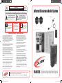
1
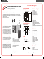
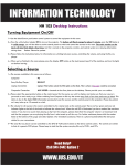
CAUTION
RISK OF ELECTRIC SHOCK - DO NOT OPEN
!
CAUTION: TO REDUCE THE RISK OF ELECTRIC SHOCK, DO NOT REMOVE COVER OR BACK.
NO USER SERVICEABLE PARTS INSIDE. REFER SERVICING TO QAULIFIED PERSONNEL.
The lightening flash with arrowhead
within a triangle is intended to tell the
user that parts inside the product are a
risk of electric shock to persons.
This product is not designed to
function normally in strong electromagnetic fields. Consequently, the
audio quality may degrade while the
product is exposed to strong electromagnetic fields.
Normal audio quality operation will be recovered
when the strong electromagnetic field is no
longer present.
!
WARNING:
TO REDUCE THE RISK OF
FIRE OR ELECTRIC SHOCK, SO
NOT EXPOSE THIS APPLIANCE
TO RAIN OR MOISTURE.
Infrared Classroom Audio System
The exclamation point within a
triangle is intended to tell the user
that important operating and servicing
instructions are in the papers with
the appliance.
Ce produit n’est pas conçu pour
un fonctionnement dans de forts
champs électromagnétiques. Par
conséquent, la qualité sonore peut
diminuer si ce produit est exposé à
un fort champ életromagnétique. La qualité sonore
redeviendra normale après affaib-lissement du
champ électromagnétique.
IMPORTANT SAFETY INSTRUCTIONS
ATTENTION: ALL SAFETY AND OPERATING INSTRUCTIONS
SHOULD BE READ BEFORE OPERATING APPLIANCE. ALL
OPERATING AND USE INSTRUCTIONS SHOULD BE FOLLOWED WHEN OPERATING THE APPLIANCE. HEED AND ADHERE
TO ALL WARNINGS ON THE APPLIANCE AND IN THE OPERATING
INSTRUCTIONS. RETAIN ALL SAFETY AND OPERATING
INSTRUCTIONS FOR FUTURE REFERENCE.
WATER & MOISTURE - DO NOT USE THE APPLIANCE NEAR
WATER; IE. BATHTUB, WASHBOWL, KITCHEN SINK, LAUNDRY
TUB, WET BASEMENT OR SWIMMING POOL.
VENTILATION - DO NOT SITUATE THE APPLIANCE SO THAT
ITS LOCATION OR POSITION INTERFERES WITH ITS PROPER
VENTILATION. FOR EXAMPLE, THE APPLIANCE SHOULD NOT
BE SITUATED ON A BED, SOFA, RUG OR SIMILAR SURFACE THAT
MAY BLOCK THE VENTILATION OPENINGS. THE
APPLIANCE SHOULD NOT BE PLACED IN A BUILT-IN
INSTALLATION, SUCH AS A BOOKCASE OR CABINET, THAT
MAY IMPEDE THE FLOW OF AIR THROUGH THE VENTILATION
OPENINGS.
HEAT - SITUATE THE APPLIANCE AWAY FROM HEAT SOURCES
SUCH AS RADIATORS, HEAT REGISTERS, STOVES OR OTHER
APPLIANCES (INCLUDING AMPLIFIERS) THAT PRODUCE HEAT.
POWER SOURCES - CONNECT THE APPLIANCE ONLY TO
A POWER SUPPLY TYPE DESCRIBED IN THE OPERATING
INSTR-UCTIONS OR MARKED ON THE APPLIANCE.
GROUNDING OR POLARIZATION - PRECAUTIONS SHOULD
BE TAKEN SO THAT THE GROUNDING OR POLARIZATION
MEANS OF THE APPLIANCE ARE NOT DEFEATED.
POWER CORD PROTECTION - POWER SUPPLY CORDS
SHOULD BE ROUTED SO THAT THEY ARE NOT LIKELY TO
BE WALKED ON OR PINCHED BY ITEMS PLACED UPON OR
AGAINST THEM, PAYING PARTICULAR ATTENTION TO CORDS
AT PLUGS, CONVENIENCE RECEPTACLES, AND THE POINT
WHERE THEY EXIT FROM THE APPLIANCE.
CLEANING - THE APPLIANCE SHOULD BE CLEANED ONLY
AS RECOMMENDED BY THE MANUFACTURER.
NON USE PERIODS - UNPLUG THE APPLIANCE POWER
CORD FROM THE OUTLET WHEN LEFT UNUSED FOR A
LONG PERIOD OF TIME.
OBJECT & LIQUID ENTRY - CARE SHOULD BE TAKEN SO
THAT OBJECTS DO NOT FALL AND LIQUIDS ARE NOT SPILLED
INTO THE ENCLOSURE THROUGH OPENINGS.
DAMAGE REQUIRING SERVICE - THE APPLIANCE SHOULD
BE SERVICED BY QUALIFIED SERVICE PERSONNEL WHEN:
(A) THE POWER SUPPLY CORD OR THE PLUG HAS BEEN
DAMAGED (B) OBJECTS HAVE FALLEN OR LIQUID HAS BEEN
SPILLED INTO THE APPLIANCE (C) THE APPLIANCE HAS BEEN
EXPOSED TO RAIN (D) THE APPLIANCE DOES NOT APPEAR TO
BE OPERATING NORMALLY OR EXHIBITS A MARKED CHANGE
IN PERFORMANCE (E) THE APPLIANCE HAS BEEN DROPPED
OR THE ENCLOSURE DAMAGED.
SERVICING - THE USER SHOULD NOT ATTEMPT TO SERVICE
THE APPLIANCE BEYOND THAT DESCRIBED IN THE OPERATING
INSTRUCTIONS. ALL OTHER SERVICING REFER TO A QUALIFIED
SERVICE PERSONNEL.
Califone® International Inc. • 1145 Arroyo Avenue, # A • San Fernando, CA 91340 USA
Toll Free 800.722.0500 | Toll Free Fax 877.402.2248
International Customers call 818.407.2400 or Fax 818.407.2405 califone.com
PA-IRSYS Operating Instructions
October 2008
califone_PA-IRSYS_manual_Rev2.indd 2-3
3/12/2010 12:39:56 PM
PA-IRSYS Infrared Classroom Audio System
Operating Instructions
Control Panel Descriptions
Front View, Front Facing Panel
(5)(6) (9) (10)(13)(18) (12)
Thank you for purchasing the Califone® PA-IRSYS Infrared Classroom Audio System.
We encourage you to visit our website www.califone.com to register your product for its warranty coverage, to sign up to receive
our newsletter, download our catalog, and learn more about the complete line of Califone® audio visual products, including
portable and installed wireless PA systems, multimedia players and recorders, headphones and headsets, computer peripheral
equipment, visual presentation
products and language learning materials.
Front View Forward Facing Panel
A.(For
Front
Side
View ( Open door )
Sound
Adjustments)
(19)
(3)
(4)
(7)
(8)
(11)
(15)
(14)
(2)
(1)
(16) (17)
B.Front
Top View
View, Inside Facing Panel
(For System Connections)
Unpacking the Unit
Inspect the unit once the packaging has been opened for any
damage occurred during shipping & contact us immediately.
Please keep the packing material for further use.
(30)
(21)
Warranty Registration
Califone warrants the Infrared Classroom Audio System to
be free from defective material and workmanship for one
year from the purchase date (six years for the speakers).
Our “Project Intercept” Customer Satisfaction program will
replace defective parts and repair malfunctioning equipment
under this warranty when the defect occurs under normal use.
(25)
PA-IRSYS Contents
All Damage Claims Must Be Made With The Freight Carrier
Notify the freight carrier immediately if you observe any
damage to the shipping carton or product. Repack the unit
in the carton and await inspection by the carrier’s claim
agent. Notify your dealer of the pending freight claim.
• Control Panel
• Two Control Panel keys
• AC Power cord
• User Manual
• Two infrared ceiling sensors (PI30-SENSOR),
each with an integrated 32’ connecting cable
• HBM-316 microphone used with beltpack transmitter
• Teacher Beltpack transmitter (PI30-BP)
• Beltpack lanyard with neck strap
• Student handheld microphone (PI30-HH)
• Four 1.2V AA Rechargeable NiMH batteries (for use
with handheld and beltpack microphones)
• Two non-powered PI30-SP
Returning Your Unit for Service or Repairs
Should your unit require service, contact our Customer
Service Department online at califone.com/techsupport
or via email [email protected] or by phone at 800722-0500 / 818-407-2400 to first obtain an RA number
before returning it back to Califone. The unit must be returned
to our factory via prepaid transportation only after the
factory issues an RA (Return Authorization) number
which must be clearly written on the outside of the box.
PA-IRSYSB
• PA-IRSYS with two additional powered
(PI30-PS) array speakers
1
califone_PA-IRSYS_manual_Rev2.indd 4-5
(20)
(24)
(28)
(35) (31)
(22 )
(26 )
(23)
(27)
(32)
(35)
(1) Power Switch
(2) Main Power Fuse (3.15A)
(30)
(31)
(3) IR Teacher Mic Volume Control
(4) IR Student Mic Volume Control(22)
(20)
(23)
(5) IR Signal Indicator (Teacher Mic)
(21)
(26)
(6) IR Signal Indicator (Student Mic)
(24)
(27)
(7) Mic 1 Volume Control
(25)
(32)
(8) Mic 2
Volume Control
(28)
(9) Aux 1 Volume Control
(29)
(10) Aux 2 Volume Control
(11) Treble Level Control
(12) Bass Level Control
(13) Master Volume Control
(14) Beltpack Transmitter Recharging Station
Beltpack
Transmitter Recharge Status Indicator
C. (15)
Bottom
View
(16) Power Adapter
(17) Handheld Microphone Recharging Station & Status Indicator
(33)
(18) Handheld Mic Holder
(34)
(19) Door Lock
Front View Inside Panel
(20) Mic 1 Input (Balanced XLR)
(33)
(21)Aux
Mic 2Input
Input (Unbalanced
(22)
1 (3.5mm) 1/4”)
(29) (1) Power Swich
(34)
(22) Aux Input 1 (3.5mm)
(35)
(2) Main Power Fuse (3.15A)
(23)
Output(Mono
(Mono
(23)Line
Line Output
1/4”)1/4”)
(24)
Aux
Input
2
(Stereo
RCA)
(3) IR Teacher Mic Volume Control
(24)
Aux Input 2 (Stereo
RCA)
(25) Mic Pre-out (Mono RCA)
(4) IR Student Mic Volume Control
(26)
DC
18V
In
(25) Mic Pre-out (Mono RCA)
Top
View
(5) IR
Signal Indicator (Teacher Mic)
(27) DC Out
(26)
18VOutput
In (+ terminal)
(28) DC
Speaker
(6) IR Signal Indicator (Student Mic)
(29) Speaker Output (- terminal)
(27)
DC OutCeiling Sensor Input (B)
(7) Mic 1 Volume Control
(30) Infrared
(38)
(28)
Output
(+ Input
terminal)
(31) Speaker
Infrared Ceiling
Sensor
(A)
(8) Mic 2 Volume Control
(32) Speaker
Cable Holder
(29)
Output
(terminal)
(9) Aux 1 Volume Control
(33) Paging Input Volume Control
(10) Aux 2 Volume Control
(34)Infrared
Paging Input
Jack Sensor Input (B)
(30)
Ceiling
(35)
25V
/
70V
Paging
Input Sensitivity Switch
(11) Treble Level Control
(31) Infrared Ceiling
Sensor Input (A)
Bottom View
(12) Bass Level Control
TopCable
and Bottom
(32)
Holder Views
(13) Master Volume Control
(33)
Box Door
(36) Panel Door
(36)
(38 )
(14) Beltpack Transmitter Recharging Station
(37)
(34) AC
ACInput
Input
(37 )
(15) Beltpack Transmitter Recharge Status Indicator (38) Knockouts to feed wires through
(35) Knockouts
(16) Power Adapter
(17) Handheld Transmitter Recharging Station & Status Indicator
Visit us online at califone.com
(18) Handheld Mic Holder
(19) Door Lock
(20) Mic 1 Input (Balanced XLR)
(21) Mic 2 Input (Unbalanced 1/4”)
2
3/12/2010 12:40:02 PM
(15)
(16)
(17)
(18)
(19)
(20)
Power LED Indicator
Lock
Ceiling Sensor Cable Plugs
EXT Speaker Jack
Front Cover
AC Cord
B.Rear Panel
Specifications
General
FM
Modulation
50Hz~15KHz 3dB
Frequency Response
80dB
SNR
Control Panel
50W MAX
PowerSpeakers
Output
than 1% of
Distortion
CAUTION: The included PI30-SP speakers have aless
total impedance
The Control Panel has two possible mounting configurations:
Beltpack Transmitter and
(17) (18)Mic
(20)Description
(19)
Installation
Beltpack Transmitter Transmits Voice to the Infrared Ceiling Sensors
(1)
(2)
(3)
(4)
(5)
(6)
(7)
(8)
(9)
Power LED Indicator
Power Switch
Battery Cover
Infrared Transmitting Head
MIC-IN Jack
DC-IN Jack/Battery Charger
Volume Control
Belt Clip
Battery Compartment
1. Option 1: The default configuration is the surfacethan 2pcs PI30-SP should be connected to the PA-IRSYS to avoid
mount the box on the wall. The mounting ears are
Transmitting
Modedropping too low for the amplifier
Infrared
the impedance
output. Speakers
designed with 4 holes for screws. Wall anchors or other
Transmitting
Frequency
ortotal
2.85Mhz
with higher
impedance ratings can be used as2.35MHz
long as the
hardware should be used as necessary to securely
load impedance
attach the box to the wall.
Transmitting
Range on the amplifier is not below
40 approximately
feet
3 ohms.
Option 2: The second configuration is a flush-mount. The
Battery
2x1.2V rechargeable2.batteries
1. Consumption
Install each of the PI30-SP non-powered
speakers on
mounting ears can be unscrewed, flipped around and
Current
240mA
the front & back walls of the room. Optimal placement is
unscrewed into the holes towards the front of the box.
approximately 3 feet below the ceiling in the middle of
In this configuration, a hole will need to be made in
Infrared Receiver
the wall.
the wall the same size as the control panel. The control
Receiving
Mode
Infrared
panel will protrude from the wall only enough to allow
Note: If the PA-IRSYSB package has been purchased, then 4
for the door to open fully.
Receiving
Frequency
2.35MHz
or
2.85MHz
speakers (2 non-powered + 2 powered) can be connected to
AF Output
650mV speakers
AF 1KHz Tips:
the PA-IRSYS Control Panel. The PI30-SP (non-powered)
•
Install the panel in an accessible area of the classroom
Dimensions
(W)120x(H)300mm
should be connected as described above. The(L)270x
PI30-PS speakers
where computers and other external media sources
should be connected as follows:
can be easily connected to the panel.
1. Install the PI30-PS speakers on the wall in the desired locations.
•
Note that longer runs of cable and poorly shielded
2. Connect the line output (1/4”) of the control panel to one of
cable can cause hum or other noise to enter the system
the line inputs on one of the PI30-PS speakers (RCA jacks).
and output through the speakers and other outputs.
3. Connecting the second PI30-PS speaker:
•
Plug the power of different equipment into the same
4. Option 1: The speakers can be daisy-chained by connecting
power outlet when possible to avoid ground loops. Also
one of the line outputs (variable or fixed) on one PI30-PS
see “Connecting the System” on the right side of the
speaker to the line input of the other PI30-PS speaker.
inner door panel.
5. Option 2: A splitter may be put on the line output from
about 5.3 ohms when connected in parallel. Therefore, no more
Infrared
Microphone
(4)
(5)
(2)
(1)
(6)
(8)
(3)
(7)
(9)
PI30-HH
handheld student
microphone
Connects to receiver panel
(16)
6.
HBM-316 microphone
shown with PI30-BP
beltpack transmitter
the control panel so that each PI30-PS speaker is fed with
its own cable.
Volume adjustment: Depending on if the speakers are
daisy chained and if the fixed or variable line outputs,
were used, the method to adjust the volume will be
different. Adjust the volume levels of each of the speakers
to achieve a balanced sound field in the listening area.
Connecting the System Once the
Control Panel is Installed
Note: The connections described in the following section
are found on the the inside facing panel of the control box.
1. Connect the two PI30-SP speakers to the Speaker
Output Jacks (28, 29).
2. Connect the two individual or daisy-chained signal
cables from the infrared ceiling sensors to the Infrared
Ceiling Sensor Jacks (30, 31).
3. Connect the AC power cord to the Power Connector
(34) on the bottom of the Control Panel and then to the
wall outlet.
4. If an external amplifier or assistive listening system is
used, connect the amplifier/assistive listening system
input to the Line Output Jack (23).
5. When using an external sound source (such as a DVD/
VCR, computer or a Califone® media player), connect
the output from the media source to one of the Aux In
Jacks (22, 24). Depending on the cable you have and
the output jack type of the external source, you may
use either 3.5mm jack (Aux 1) or the RCA jacks (Aux 2). All
Infrared Ceiling Sensors
1.
Infrared Ceiling Sensors (two units are included)
(1) Receiver Cover
(2) Fixed Ear
(3) Infrared External Input
(4) Infrared External Output
(5) Signal Cable with 32’ cord
2
1
2
4
3
1
5
Specifications
Visit us online at califone.com
General
)
califone_PA-IRSYS_manual_Rev2.indd
Modulation
Frequency Response
SNR
6-7
Power
Output
3
FM
50Hz~15KHz
80dB
50W MAX
3dB
Install the two included infrared ceiling sensors along
an imaginary center line in the middle of the ceiling, with
each sensor located approximately one third of the length
of the room away from the back or front wall.
Note: With proper installation, the Classroom Audio system
(with two ceiling sensors) can be used in rooms up to 2,000 sq.
feet in size. If greater coverage is needed, up to 4 ceiling sensors
can be daisy-chained & connected to the control panel.
Tip: If reception of the infrared microphones is noisy or the
signal cuts out, try moving and/or rotating the receivers until
better reception is obtained.
Visit us online at califone.com
4
3/12/2010 12:40:05 PM
Installation & Operation
6.
7.
8.
stereo signals are automatically mixed down to a mono
signal for playback through the system. The volume
for the inputs can be controlled by the Aux Volume
Controls (9,10).
Turn all the Volume Controls to their minimum position
(approximately 7 o’clock). The Treble and Bass (11, 12)
controls should set to 12 o’clock (straight up).
Turn on the Power Switch (2) and the power LED
Indicator will light.
The PA-IRSYS should now be operational. The Treble
(11) and Bass (12) Control knobs can be adjusted to
improve quality/intelligibility of the audio through the
system.
4.
Adjust the paging input volume to the desired setting.
Note that the Master Volume must be also turned up for
the signal from the paging system to be heard through the
PA-IRSYS speakers. Due to this, the PA-IRSYS should not be
relied on for emergency paging or announcements.
Operating the Infrared Belt Pack
and Handheld Microphones
Notes:
•
The volume adjustments for the two wireless mics, the
two auxiliary inputs, and the Master System controls
described in the following section are found on the front
facing panel.
•
The Beltpack Transmitter comes with a lanyard that can
be slipped over the belt pack and hung around the neck.
Connecting the System for Teleconferencing
The Califone PA-IRSYS is specifically designed to work with
PC/MAC teleconference systems such as Microsoft®
Netmeeting.
1. When using a computer teleconference system plug
the Mic Pre-out (25) to the line input on the computer.
2. Connect the PC line/headphone output to the Aux 1
(22) or Aux 2 Input (24) on the Control Panel.
3. By connecting the system in this configuration, all of
the microphone signals from the PA-IRSYS (the wireless
teacher & student mics, and connected wired mics 1
and 2) are mixed and sent into the PC and sent to the
remote teleconference site. The microphone signals will
still also come out of the PA-IRSYS speakers along with
the audio from the remote teleconference site.
4. You can adjust the Master Volume (13) and Aux Input
Volume (9, 10) to get an appropriate loudness and mix
of the signals.
Note: You may need to adjust volume settings of the
microphones as appropriate to get a good level signal into the computer. You may also need to adjust sound settings in the application to use the appropriate inputs/outputs for the audio on your computer.
Tip: Do not connect the Mic Pre-out to the microphone
input of the computer as you may get a distorted sound.
1.
2.
3.
4.
5.
6.
Connecting the System to a 25 / 70 / 100V
Paging System
Insert two 1.2V AA rechargeable batteries into the infrared
Beltpack Battery Compartment (9), paying attention to the
positive and negative poles. Then close the battery cover
Turn on the Microphone Power Switch (1) and the power
LED indicator will light, indicating that transmitter is ready
to use. A couple seconds later the appropriate IR Signal LED
(5, 6) will light red, meaning the receiver has good signal
reception from that particular mic.
If using the beltpack transmitter, adjust the Volume Control
(7) on the side of the beltpack. Also, adjust the appropriate
Wireless Mic Volume Control (7, 8) on the panel. The Master
Volume will also need to be adjusted to an appropriate level
At this point, the microphones should be heard through
the system.
Both of the wireless microphones can be used throughout
a typical day on a single charge and should be recharged
overnight while not in use (without taking out batteries).
Both the Beltpack and Handheld Mics have Built-in
Chargers (14, 17) and are to be placed into their respective
charging stations and charged overnight.
The LEDs on the Handheld and Beltpack Microphone
chargers indicate when the system is charging the
microphones and when charging is complete. The LEDs will light up red when charging and will turn green once
the batteries are fully recharged.
The output of a 25 / 70 / 100 V Paging System may be
connected to the PA-IRSYS paging input for non-emergency
paging.
1. To do this, first wire the paging system output to the
included 2-pin phoenix connector.
2. Then plug the connector into the paging input jack.
3. Adjust the sensitivity switch to the appropriate setting.
Visit us online at califone.com
5
califone_PA-IRSYS_manual_Rev2.indd 8-9
Operation & Specifications
General Notes
•
•
•
System Specification
Storage Temperature:
Operational Temperature:
Power Supply:
The Master Volume controls the overall volume of the
system. If the master volume is not up, then no sound will
be output from the system speaker outputs.
Because the PA-IRSYS wireless microphones use infrared signals, they are not suitable for outdoor use since direct sunlight can interfere with the transmission.
Do not cover the infrared transmitter head on either the
handheld microphone or the belt pack microphone as
the transmission to the ceiling sensors requires line-ofsightfor clear noise-free operation.
Amplifier
Power: Frequency Response:
THD: -25oC – 65oC
0oC – 45oC
Integrated 100-240VAC 50/60Hz switching power supply
30W RMS
(+/- 3dB): 20Hz – 20kHz
<1%
Infrared Microphones
Belt Pack Microphone
Carrier Frequency:
Handheld Microphone
Carrier Frequency:
Microphone Recharging Time :
(both handheld and beltpack)
Microphone Operational Time: (both handheld and beltpack)
Max Range: Troubleshooting
There is no sound output.
• Is the AC cord connected the Control Panel and
to the power outlet?
• Is the power switch on and the power LED lit?
• If using the beltpack transmitter:
• Is the power on the beltpack on and the
power LED on the beltpack is lit?
• If not, try new batteries.
• Is the Teacher Mic Signal Indicator lit
on the Control Panel?
• If not, make sure the ceiling sensors are picking up the signal from the
beltpack and that the IR transmission
is not being blocked.
• Is the volume control on the beltpack up?
• Is the Teacher Mic volume control up?
• Is the Master volume control up?
• Are the speakers connected to the speaker outputs?
2.35MHz
2.85MHz
Approx. 8 hours Approx. 5-6 hours
continuous usage
40 feet
(From microphone to
ceiling receiver)
If the above section has not fully answered your
question, visit the FAQ section of our website
califone.com/faqs or contact our Customer Service
Department directly via email ([email protected])
or by phone at 800-722-0500 / 818-407-2400.
There is feedback from the speakers.
• Try decreasing the volume of the
microphone, master volume control, etc.
until there is no feedback.
• Try adjusting the treble and base controls
to reduce feedback.
There is noise or hum from the speakers.
• Check the installation:
• Ensure that cables are as short as possible
and not run next to noise-generating cables
or equipment.
• Ensure that power cables of different
equipment use the same power outlet
to avoid ground loops.
Visit us online at califone.com
6
3/12/2010 12:40:06 PM
Complimentary Products
Complimentary Products
The following Califone products compliment your Infrared Classroom Audio System
Media Players
to connect to the
Classroom
Audio System
CD102
Personal CD Player that’s
built school tough
8102
2396
The first MP3 player
designed for school use
with a built-in mic for
podcasting and dual
headphone jacks
Multimedia player with variable
speed playback and built in USB port to transfer
files to and from a computer
Visit us online at califone.com
7
califone_PA-IRSYS_manual_Rev2.indd 10-11
Visit us online at califone.com
8
3/12/2010 12:40:13 PM
Array Speakers
Caution
Improper installation can cause serious injury. The hardware and this installation guide of the speakers and this system
were designed for wall-mounted applications. For ceiling mounted uses, use only industry approved mounting
methods and hardware. Califone will not be responsible for improper installation or subsequent damage.
Depending on the chosen method/configuration of installation of the PA-IRSYS system, various national and local
electrical and fire safety/building codes may be applicable. Please reference those codes before installing the PA-IRSYS
to ensure compliance of the installation. Califone does not provide any warranty for improper installation of the PA-IRSYS
or its components.
Notes
Clamping
of any
PI30 Series
Field Array
Speaker
Wall
Mounting
of any PI30 Series
Field Array
Speaker
———————————————————————————————————————————
———————————————————————————————————————————
———————————————————————————————————————————
———————————————————————————————————————————
———————————————————————————————————————————
WARNING
———————————————————————————————————————————
Improper installation can cause serious injury. Use only industry approved mounting methods and hardware.
Califone cannot be responsible for improper installation or subsequent damage.
———————————————————————————————————————————
———————————————————————————————————————————
———————————————————————————————————————————
———————————————————————————————————————————
PI30-PS
PI30-SP
Powered
Field Array
Speaker
Non-Powered
Field Array
Speaker
———————————————————————————————————————————
———————————————————————————————————————————
———————————————————————————————————————————
———————————————————————————————————————————
———————————————————————————————————————————
Visit us online at califone.com
9
califone_PA-IRSYS_manual_Rev2.indd 12-13
10
3/12/2010 12:40:16 PM