1
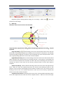
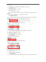
c) P2;After depth adjustment, recording the pulse of axis corresponses to Slot Depth Adjustor
Axis: P2
d) Measure the actual length S for Depth Adjust Axis.
e) Slot Depth Adjustor Axis Pulse=(P2 – P1)/S’
f) Choose average value after many tests
G. Rvs Slot Push/Reject Aixs Pulse
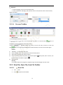
a) P1;Observe the ‘pulse monitor’, recording the pulse of axis corresponses to Slot Depth
Adjustor Axis.
b) Input S in Manual Dis, and click ‘P/R’
c)
d)
e)
f)
a)
P2;After Rvs Slot Push/Reject, recording Rvs Slot Push/Reject Aixs Pulse
Measure the actual length S for movement of Rvs Slot Push/Reject
Rvs Slot Push/Reject Aixs Pulse=(P2 – P1)/S’
Choose average value after many tests
H. Rvs Slot Depth Adjustor Axis
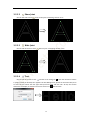
Observe the ‘pulse monitor’, recording the pulse of axis corresponses to Rvs Slot Depth
Adjustor Axis P1;
b) Input S in ‘Manual Dis’, and click ‘Depth Adjust’
c)
d)
e)
f)
After Rvs Depth Adjust, recording Rvs Slot Depth Adjustor Axis pulse P2.
Measure the actual length S for movement of Rvs Slot Depth Adjustor
Rvs Slot Depth Adjustor Axis pulse=(P2 – P1)/S’
Choose average value after many tests
5)
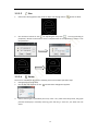
IO Setting
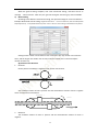
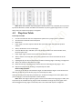
The setting of IO is corresponse to ‘Mechanical Control Setting’. Please see the chart, black is
can be choose and gray is can not be choose.
14