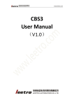
1
S tephan M erz • Blumenstr. 24 • D- 82407 W ielenbach Tel. 0881/ 92700- 50 • Fax- 52 • mobil 0178/ 7603625 • email: inf o@ S M - M odellbau. de JLog2 data logger Special JIVE logger and more Description and Instruction Manual 1 INTRODUCTION...............................................................................................................................................................................2 2 DIFFERENCES BETWEEN JLOG2 AND JLOG1........................................................................................................................2 3 DATA LOGGED AND DISPLAYED BY JLOG2 .........................................................................................................................3 4 LOGMODES.......................................................................................................................................................................................3 5 CONNECTING THE LOGGER.......................................................................................................................................................3 6 CONFIGURING THE LOGGER......................................................................................................................................................4 7 MICROSD CARD AND FILE SYSTEM..........................................................................................................................................6 8 LEDS OF THE LOGGER..................................................................................................................................................................8 9 EVALUATION OF LOG FILES.......................................................................................................................................................9 10 TELEMETRY.................................................................................................................................................................................11 11 THIS AND THAT...........................................................................................................................................................................15 © 2011 SM Manual JLog2 v3.1 1 Introduction J-Log.net 1 Introduction JLog is a special data logger processing the diagnostic data stream of a JIVE series ESC – data of the JIVE's internal sensors and other data of the ESC. The logger stores the output as log files on a microSD card and drives a live stream through an USB interface or telemetry. Plotting of logs is preferably done by LogView Unique features are: o high data capacity, small dimensions, low power requirement o no data transfer required prior to data evaluation o no complex cabling o capturing of data that a native logger can't provide o measurement readings not integrated (no rms values) what leads to real-life amplitudes o configurable alarms - alarms by telemetry and/or alarm lines o configuration and updating from the SD card (The logger can be used with every JIVE regardless of its firmware version.) 2 Differences between JLog2 and Jlog1 Both loggers are of identical dimensions (“stamp”) but based on different hardware: JLog2 o connections for additional JLog-own sensors: analog temperature sensor or up to 5 digital temperature sensors or RPM sensor or up to 2 alarm lines (With a simple D.I.Y. adaptor also temperature sensor(s) and RPM sensor may be connected at the same time, or one type of sensor and an alarm line.) o connection for live data via an optional USB interface or telemetry o 9 instead of 4 alarm types before o motor current calculation now more granular at all and more exact in border areas o floating offset for calibration of values for motor and BEC current o calculation of cumulative mAh more precise once again o now 31 in place of before 13 (respectively 18 with v.2.7) log values in LogView o alternative to configure the logger also without a PC (JLC) by a JETIbox o updating JLog2 is no more individualized and done by a file on the mSD. Because of more exactly calculating the motor current in the upper border area peaks at high slew rates of the current can reach up to 7% higher in the log than with JLog1. page 2 3 Data logged and displayed by JLog2 J-Log.net 3 Data logged and displayed by JLog2 Measurement readings and signals: U-BEC [V] U-BAT [V] I-Motor/Int [A] PWM-Motor [%] RPM-Motor [1/min] Temp-PA [°C] Power [W] IbecMax [A] BEC output voltage main battery voltage motor current (integrated) ESC ”opening” motor’s RPM temperature of the PA motor input power peak BEC current I-BEC [A] I-Motor [A] Throttle [%] RPM-Uni [1/min] Capacity [mAh] Temp-BEC [°C] Power/Int [W] ImotMax [A] ALARM: Capacity [S] ALARM: TempPA [S] ALARM: EXT: T1 [S] ALARM: EXT: T3 [S] ALARM: EXT: T5 [S] EXT: Temp2 [°C] EXT: Temp4 [°C] EXT: RPM [1/min] alarm on cumulative mAh alarm on PA’s temperature alarm on ext. temperature 1 alarm on ext. temperature 3 alarm on ext. temperature 5 external temperature 2 external temperature 4 external RPM ALARM: Ubat [S] alarm on main battery voltage ALARM: UbecDrop [S]alarm on drop of BEC voltage ALARM: EXT: T2 [S] alarm on ext. temperature 2 ALARM: EXT: T4 [S] alarm on ext. temperature 4 EXT: Temp1 [°C] external temperature 1 EXT: Temp3 [°C] external temperature 3 EXT: Temp5 [°C] external temperature 5 4 BEC output current motor current throttle impulse length rotor or propeller RPM cumulative mAh temperature of the BEC motor input power (integrated) peak motor current LOGmodes Before LOGmode we have the SYSmode o SEQLOG-Mode: data subsequently appended to a log file o NEWLOG-Mode: with each power-up a new subsequent numbered log file is written This is the preferred SYSmode. The LOGmodes: o LOGmode 0 (OF/LV) recording log files as OpenFormat for LogView with extension „.txt“ o LOGmode 2 (SER) for recording of any serial data into log files with Extension „.slg“ o LOGmode 8 (JLV) recording binary data of a JIVE into log files with Extension „.jlg“ 5 Connecting the logger JLog2 is connected by a servo patch cable to the diagnostic connector of the JIVE. This is the connector otherwise used for modus programming with a jumper. The brown wire of the cable (ground) points to the outer face of the JIVE. WARNING: The connection assembly of the logger should be in no case connected to other R/C equipment or the „Master” or „Slave“ socket of the JIVE because the logger could be damaged by that! The jumper should not be connected to the JIVE during power-up because the ESC wouldn’t send no data though! Best is to have the logger already connected before connecting the main battery. Please keep in mind that the logger on its serial interfaces uses a voltage level that isn’t compatible to that of computer interfaces, of your PC for example! Connecting to a computer interface would destroy the logger! Note also that the servo cable connecting the JIVE is atypical assigned. The yellow wire is (+), the red is signal! This assignment holds danger of reverse polarity – although this wouldn’t damage the logger. On necessity the cable to the JIVE can be extended to a maximum length of two meters. page 3 5 Connecting the logger J-Log.net Reverse polarity and wrong connection: All connections of the logger are protected against reverse polarity as long as the voltage range does not exceed +/- 6 volts, - 6 volts is the maximum BEC voltage of the JIVE. Anyway double check the connection not to have reverse polarity. If running the logger autonomous – without a JIVE with another supply voltage – please note: Do not exceed a maximum supply voltage of 6 volts! Do not wire the supply voltage wrong way around! 6 Configuring the logger With each startup JLog2 learns the configuration from the file „CONFIG.txt“ located in the root directory of the SD card. A user modifies the content of that file by a PC for modification on the configuration of the logger. Alternatively a JETIbox can be used for configuration, provided JETI telemetry is switched on. If „CONFIG.txt“ inadvertently have been deleted, JLog2 will automatically re-create it with the last configuration stored in the processor. Faulty insertions into „CONFIG.txt“ will be recognized by JLog2, ignored and the config file will be automatically corrected. Creation/modification of CONFIG.txt on the SD card is done by the PC tool JLog Configurator (JLC) – which you please install on your PC. The installation software can be found for download on the web site of SM-Modellbau or that of JLog respectively. JLC has a built-in help. Not only JLC than also the logger provides for obviousness of the content of CONFIG.txt. That means that also the logger itself checks the configuration and will correct it if necessary. He’s doing that concerning the setup he found in his non-volatile memory (EEPROM) and also while reading CONFIG.txt if the file is existing during startup. CONFIG.txt will always be rewritten by he logger in result of a check. The logger stores the last read and as good considered configuration in his non-volatile memory, the EEPROM. That means you may insert an empty SD card - the logger will create CONFIG.txt by itself - and also all other files and a necessary sub-directory (the next one following the running number) for log files. Also the running log file number is stored by the processor. If the RST flag (reset) is set by JLC, the number will be reset to zero and all log files and log directories will be deleted with the next start. JLog2 will clear the flag then and rewrite the config file with an unset flag. „Basics“ JLC provides concerning „RPM-Uni“ - RPM of the rotor of a helicopter or that of a propeller with a geared motor - three ways of input: 1. Input of the integer number of tooth of the pinion and the main gear (1-stage gear) 2. Use of the real pinion and a virtual main gear at which it is possible to run fractions of a tooth (two decimal places). This can be helpful for helicopters with multiple-stage gears. In this case one often only knows the overall reduction gear ratio but not the number of tooth of the involved cog wheels or drive pulleys. 3. Direct input of the reduction gear ratio For proper recording of „RPM-Uni“, at first „RPM-Motor“ have to be okay for which the accurate number of magnetic poles of the brushless motor has to be used. (The selection in JLC offers named motor types also. It cannot be guaranteed that the corresponding number of poles behind is the right one. Please always check the manufacturer’s web site on how many poles a motor has.) page 4 6 Configuring the logger J-Log.net Alarms Four of the possible alarms correspond to values from the JIVE, five more to temperatures of up to five optional temperature sensors connectable to the logger. The four JIVE alarms are: CapMax UbatMin TempMax UbecDip alarm if cumulative milliamphours exceed the configured trigger value The value reads as n x 100mAh. alarm if main battery’s voltage drops below the configured trigger value alarm if the PA’s temperature exceeds the configured value alarm if the BEC voltage in more than four subsequent gauges drops >0.5 volts below the value measured during startup of JIVE/JLog2. The average time interval is 500 milliseconds. UbatMin is not directly used as gauged battery voltage than as integrated measurements, - very special here for alarm triggering. This avoids alarms triggered by short term voltage drops. The five other alarms are: ExtTemp1 [°C], ExtTemp2 [°C], ExtTemp3 [°C], ExtTemp4 [°C], ExtTemp5 [°C]. In contrast to the above mentioned alarm triggers, it is possible here to use „greater than“ (>) or „lower than“ (<). Depending on the selected type of temperature sensor there are different allowed value ranges which JLC accounts. Generally for alarms applies: A zero value for an alarm trigger means that this alarm is disabled! „Optional Interfaces/Sensors“ (Hardware Configurator) The logger has two optional signal pins used for own sensors or alarm lines - and an additional serial interface for the OpenFormat livestream or for connection to a telemetry system („COM“). Originally there can be only ONE servo plug used on connection K4 – for ONE sensor or up to two alarm lines in one servo lead. The configurator JLC works like a little expert system. The configurator takes notice of user requests, coordinates with possibilities for fulfillment – in which sensors have priority over alarm lines – and displays effective use of the interfaces. Should fulfillment of a configuration request only be possible by use of an adaptor, then this will be signalized and the schematic of an adaptor will be displayed on demand. An adaptor must be compiled as D.I.Y. but it is quite simple. Here also applies: Numeric input of a zero means that the sensor or the alarm line is not configured. The usage of this part of the configurator is as self-explanatory by a built-in help as all other functions. The following shall be pointed out anyway: Having configured a RPM sensor you may add it to the LogStop function by „extRPM affecting“ in „Basics“. LogStop will not be going active as long as in addidtion to the conditions given by Imot and Ibec the rotation speed from a JLog2-own RPM sensor is not zero. page 5 6 Configuring the logger J-Log.net „Pulse p.Revo“ defines „pulses per revolution“ that a RPM sensor generates as long as it is no brushless RPM sensor. The checkbox „It’s a Mot“ („it’s a motor“) alters the timeout behavior of the RPM measurement. In case that pulses stop to drop in, the only thing the logger can do is to set the speed to zero – for low speeds later than for higher ones. This checkbox lowers the time after which – in case pulses drop out – the speed is corrected to zero. If „It’s a Mot“ is checked you may in addition check „BL“ (brushless motor) so you can select the number of poles the motor has. RPM pulses are awaited now to come from a brushless sensor. Digital temperature sensors are of type Dallas DS18B20 connected via an One-Wire-Bus with the Dallas-One-WireProtocol. You may connect an arbitrary number between one and five of those sensors. Only the software is limiting the number to a maximum of five. Each sensor of this type carries a world-wide unique lasered marker - the so-called “ROM code” (64 bits). With each start the logger scans these ROM codes of sensors connected to the bus. The order of recognition is determined only by the code of each sensor, what means that the ordering of sensors into the five measurements of external temperatures is always the same. If you wish to connect more than one digital sensor you have to use conventional Y servo leads. The electrical sequence of the sensors has no influence on the sequence of order regarding the five measured values. Only the ROM codes affecting it. If digital temperature sensors are connected via a required adaptor – means a RPM sensor or an alarm line in parallel – an additional pull-up resistor of 10 kiloohms is needed – between signal and (+). (+) in this case is the positive end of the JIVE's voltage, as found on K5-3. – Without an adaptor, if connecting digital temperature sensors by a servo jack to K4, this pull-up is not needed because it a) exists in the logger itself, switched-on by the software following the configuration and b) K4-2 provides a positive voltage of about 3 volts. That way the internal pull-up goes effective. An analog temperature sensor does not need an additional pull-up resistor. If two alarm lines are configured, the second line is controlled by alarms on cumulative mAh. Alarm lines are low-active, they supply about 3.3 volts and drive up to 33 milliamps (on short-circuit) if no alarm is issued, and near zero volts by an alarm. In contrast to a sensor, an alarm line does not need a pin for voltage supply. Thus the use of two alarm lines – an additional sensor is no more possible – not really needs an adaptor than a single servo lead like with a single sensor type. The two alarms use the yellow and the red wire whereas the black or brown wire is ground, the reference voltage of the signals. Alarm devices in a R/C model will possibly be obsolete if a JLog2-supported telemetry system is used. Schematic propositions for alarm devices can be find on the website of JLog. 7 microSD card and file system Please use as possible the SD card which we offer under the item number #2810. SD cards show depending on the type and exemplar big differences in access times in particular during write operations. A too slow card may disturb the timing of the logger software which appears by wrong calculated mAh (by lost of data packets from the JIVE) or even by time gaps in the log file. page 6 7 microSD card and file system J-Log.net A good card is specified to belong to a „class“, visible by a number in a circle reaching from 2 to 10 for 2..10mbytes/sec. Use a class 3 at minimum. But a rated card may charge-dependent scatter very much. The card offered by us has been selected in tests and is comparatively very fast although it does not belong to a class. Here to be seen one more time the difference between global specification and practical experience. 7.1 Inserting and extracting the microSD card The card will be inserted at the front edge/front side – printed side facing outwards, in direction to the pins of the logger. In contrast to the hardware of JLog1 there is no cogging torque. For extracting, the card is simply pulled out. Avoid unnecessary touching of the contacts of the card! The card can be inserted also if the logger is already supplied by voltage. Inserting will cause a restart of the logger. Removing from the running logger should not be done as possible in LOGmode 2 (SER) and in all other modes only if LogStop is used and currently active - respectively JLog2 is detached from the JIVE. The SD socket has a contact which opposite to JLog1 is connected and used. The logger detects if the card is extracted and signalling this with its LEDs. In return, via the socket contact it will be detected that the card has been just inserted. Did that happen with an adequate speed (not too slow on part of contact making) the logger will be reset and start over – in the same manner as if when the supply voltage just have been connected. But did it happen too slow – the socket doesn’t have the accelerating mechanism like with JLog1 – then a reset followed by adjacent initializing of the card could not be done. JLog2 signalling this by a dimmed glowing of all three LEDs. In this case the card has to be inserted again. 7.2 Apparently defective SD card The situation cannot occur if the card is exclusively used with JLog2 but it could be that you try to use a card that have been used in other devices before. The problem appears like that the card isn’t readable by the logger but may be still usable by a native operating system. Although a card definitely can successfully be formatted under such an OS - in this case it is essential to format the card by a special SD-Formatter which you can download from here: http://www.sdcard.org/consumers/formatter/#download A SD card of a capacity of more than 2GB is a so-called SDHC Card („HC“ for high capacity) formatted with the file system FAT32. JLog2 does not support FAT32! SDHC Cards therefore are not usable! JLog2 makes exclusive use of FAT16. Don’t use cards of a too low capacity. With them the file system FAT12 is used which indeed is supported by the boot loader – but not by the real software of the logger, the application! 7.3 The file system 7.4 The running file number Please do not copy your own files or directories into the file system of the SD card. You could accidentally break the conventions of the file system by that – and after that wouldn’t be no more able to use the file system, would have to format the card by your PC. In the NEWLOG SYSmode JLog2 creates up to 65535 log files. To conform with the conventions of the file system JLog2 automatically creates sub-directories in which he writes the log files. Each 511 log files will be stored into a subdirectory. Those sub-directories are named – for better locating of log files - like „d000-510“ or „d65024-65534“. With each start of JLog2 (supply voltage connected) the logger generates a new file number which is stored inside the processor. The name of the next log file will be determined and – if necessary – a new log-directory created. The log file will be created but not starting to fill-up before serial data is running in – in LOGmodes 0 (OF/LV) and 8 (JLV) not until the motor current goes above zero at least one time. Before, the JIVE must have initialized, prior it does not send time stamps which act as time base for the logger. In LOGmode 2 (SER) the log file will be recorded as soon as serial data is running in. LogStop doesn’t act a part in LOGmodes 0 and 8. This way log file numbers - from the names of the files in a log-directory - may seemingly overleap or empty log files may be stored. page 7 7.4 The running file number J-Log.net Five seconds after non-appearance of valid data from the JIVE the logger will switch to his own time base and start to record logs. This will happen in LOGmode 0 (OF/LV) only. There is no effective LogStop in this case. Naturally this mode of operation makes only sense if JLog2-own sensors for temperature or RPM are operated. LOGmode 8 (JLV) will only record if valid data of a JIVE is running in, whereas LOGmode 2 (SER) will cause recording as long as serial data is available. Because LOGmode 8 (JLV) is also passing through the data processing, as LOGmode 0 does, it drops a switchable live stream as OpenFormat too - or doing this in telemetry format depending on which is configured and independent of the conditions of the recording. Of course there is no live stream or telemetry output in LOGmode 2. The LogStop 7.5 Binary data of a JIVE ESC is continuously analyzed by JLog2 and processed to record it in a log file. An exception is here LOGmode 2 (SER) which records the serial data stream without a processing of it. Only LOGmode 0 (OF/LV) records processed data in OpenFormat for LogView. A function whose necessity is derived from continuous data analysis is the so-called LogStop: LogStop starts recording by JLog2 as soon as a motor current or BEC current > 2.9 amps is drawn – and stops recording if for at least 5 seconds no motor current or BEC current <= 2.9 amps have been gauged. Recording is restarted if motor current is again drawn or BEC current > 2.9 amps. In this way it is guaranteed that a regular cut from the main battery will not cause data lost. Should it happen that during a write onto the SD card the supply voltage drops out – then write failures are not to exclude. If it happens that single files on the SD card appear defective, the complete content of the card should be backed up if needed and the card fresh formatted. With LOGmode 2 (SER) LogStop is generally not active because incoming serial data is not analyzed - it consists „foreign data“ which is unvalued recorded in a log file. LogStop is used in LOGmode 8 (JLV) also. Peak currents IbecMax and ImotMax will not be updated if LogStop is currently active but only if the source of their origin is just logged as I-BEC or I-Motor respectively - thus LogStop is not active. Because the live stream - OpenFormat or telemetry - if switched on and despite of LogStop continuously outputs effective data – the logger uses extra stores for IbecMax and ImotMax. Until the JIVE has not initialized (sound sequence with the motor) it doesn’t send no time stamp – thus a log will not be recorded. Did the logger not see any data from the JIVE until 5 seconds after its start (the logger is possibly operated for a dedicated application without a JIVE and supplied by a foreign voltage) it will start recording on its own time base, whereas 10 records a second will be written. As soon as under this condition the logger gets data from a JIVE he changes the time base to the time stamps received from the ESC. Operating the logger without a JIVE make only sense of course if is connected to optional sensors for temperature(s) or/and RPM, means for gauges outside of the JIVE. If required LogStop can be switched-off with the above mentioned risk – for example to measure and log the BEC current in a motor glider constantly. Disabling is done by the config file <SD>:\CONFIG.txt which is handled by JLog2 Configurator (JLC) or you configure the logger “in the field” by a JETIbox. 8 LEDs of the logger The logger has three LEDs, red, orange and green. LED – red: • Continuous glow after start: Boot loader searching the file system for an update file. Does the logger not start after, red LED continuing to glow, then there is no software in the flash ROM that the logger could start. • Flashing shortly after start: Boot loader enforcing an update. • Continuous glow in operation: A serious error occured on the part of the SD card. It is quite possible that the logger can anyway continue to work. page 8 8 LEDs of the logger J-Log.net LED – orange: • „Twinkle“ during operation: Signalling write access into the file system, the log file is being written, respectively passes of data processing. • Continuous glow in operation: Signalling as „general alarm“ that one of the nine programmable alarms have been raised – and goes out if all enabled alarms have been cleared. („CapAlarm“, as trigger for an amount of cumulative mAh, cannot clear itself – the orange LED will keep glowing statically.) LED – green: • „Twinkle“ during operation: Signals receiving of serial data (from JIVE or another device). In LOGmode 2 the LED apparently will glow continuously because there is no data processing. A running light of all three LEDs means that no SD card has been found or he card has been removed in operation. A “statically dimmed” glowing of all three LEDs means inserting the SD card into the logger in operation have been too slow. Repeat the action. Synchronous flashing of all three LEDs appears in operation if HPW (High PWM Warning) is configured and the HPW condition have been reached. Identical flashing appears for 30 seconds after start and before the logger continues with regular operation if in the boot session before (with the last flight) a HPW condition was detected and stored. 9 Evaluation of log files Main application is log files ending in „.txt“, LOGmode 0 (OF/LV). These are logs in OpenFormat for LogView. LogView is donationware and downloadable from here: http://www.logview.info/vBulletin/downloads.php?do=cat&id=2 A log file will be loaded into the running LogView by import devicefile.. Import devicefile, not Open… (same as double click in an explorer), not frequently enough to point out after the experiences with JLog1! Open can LogView only files with extension „.lov“, those are exports out of LogView, also OpenFormat but with a header describing the device to use, plus further setup like colors etc. The Device describes for LogView which data per log record (line) is expected and how to interpret it. At first we have to configure an applicable device in LogView what is done by Device -> Choose device and port. The Device Dialog is opening and we go into Reduce usable devices to select all devices we want to see in the future. The applicable INIfile for JLog2 to be find as „OpenFormat\JLog2“. Now we go back to Settings in Device Dialog (my version shows up with „Gerätedialog“ although English is configured) and switch through the devices. Please select JLog2. The selection for Port is only needed if we own an USB interface and plan to display the OpenFormat live stream of the logger in LogView. At the moment LogView does not know about JLog2 originally. To have the device JLog2 LogView selectable, we need to copy the files JLog2.ini and JLog2.jpg into the LogView device directory of the PC user. The location of that directory varies over the operating systems from version to version, names within a directory area also depend on the language version of the OS. As below it is commonly describable: %appdata%\ LogView\Geraete\OpenFormat\JLog2.ini %appdata%\ LogView\Geraete\JLog2.jpg The JPEG file is only needed to get a picture of the logger displayed in Device Dialog (Geräteauswahl). The logger will show up in LogView now as seen below: page 9 9 Evaluation of log files J-Log.net In the download you will find the file Example_JLog2.lov. Simply open that file by an existing or first installation of LogView to let LogView conveniently learn the Device JLog2. The above described installation of the file JLog2.ini is no more necessary by that. Only to let Device Dialog (Gerätedialog) come up with a picture of the Device one need to copy JLog2.jpg into its location in Geraete of the LogView user directory. We may now export an imported log file (devicefile) by LogView into a file „*.lov“. This file contains already all setup including those from JLog2.ini. One may send a .lov file to another person who only needs a LogView installation to view it. By opening a file with extension „.lov“ with LogView (file open) it will automatically learn the device necessary for proper reading of contained log data. LogView – by the JLog2 device setup – is run with the time base of the logger and this way with the timing circuit of the JIVE. Time starts as soon as the JIVE has initialized (sound sequence after initialization). Otherwise the internal time base of the logger took over because no JIVE has been seen. Regarding usage of LogView: It makes relatively less sense to consider a log only as “Potpourri of colored lines” in an integral view on it. The graphical resolution can play a trick on us. Also: Points of interest should be zoomed then! Things can qualify by that and give us a “light bulb moment”. Therefore ImotMax and IbecMax have the purpose to be able better to find peak values in a general display, in a more readable manner. – But then it should be zoomed there also! Between extreme values you will see lines (diagonals) connecting two of them. Possibly it is only LogView doing that – following its default setup. This is modifiable by Graph editor (basic) and within it for each relevant measurement by clicking the check button Stairs. Please also play a bit with all the other comprehensive functions of LogView, the export into a spread sheet for example or Analysis -> Min/Max. 9.1 Info file in the file system of the microSD card In addition to log files created by LOGmodes 0 (OF/LV) and 8 (JLV), a file <SD>:\JIVEinfo.txt is originating and updated during the start of a new log session in the above mentioned LOGmodes. The file contains two informational items in a line, separated by a space: 1. A cipher or number naming the software version of your JIVE, a „9“ for version 9 for example. 2. A number which refers to the overall runtime (seconds after initialization) of your JIVE. From release 9 on there is no more the runtime given out by the JIVE, the corresponding field contains „N.A.“. If a JIVE’s data stream have never been seen, the first field will contain „?“. With LOGmodes 0 and 8 JLog2 is processing data running in from the JIVE and extracting by that also this information. These will be stored in the non-volatile memory (EEPROM) within the current log session. At the start of a new log session (JLog2 off/on) both data will be transferred into the file <SD>:\JIVEinfo.txt. Means the runtime found in the file refers to the start time of the log session before. page 10 9.2 High PWM Warning (HPW) 9.2 J-Log.net High PWM Warning (HPW) Motivation: This function is a quick help for setup of the JIVE modes 4 and 11, governor modes. Depending on the power and applied load and the battery voltage respectively, the ESC has to control the motor PWM (according to the value of throttle also), - commonly referred as “opening”. Considered over the log time there is a slow factor, - the decreasing average battery voltage, - and two fast factors, - RPM drops by the performance limit of the motor and voltage drops by the internal resistance of the battery, - which force the ESC to counteract by raising PWM. The higher throttle was now chosen, the more likely it is towards 100% PWM – if above components due to their performance cause a RPM drop which is to be compensated. If motor PWM is often at the limit of 100%, the ESC has no reserves to control. HPW as a quick display without having a PC at hand for evaluation of logs: If PWM is now for more than or at least the half of the commutation time (runtime of the motor) greater than 95%, then this will be registered in the running log session by the logger, by a flag in its EEPROM. Concurrently the logger lets all three LEDs synchronously flashing, what you usually can’t see.;) At the next start of the logger that flag will be checked and if set now also all three LEDs will flash synchronously, 10x fast (50ms pulses) with a break of half a second each. The logger will remain now for 30 seconds in this flashing loop and then continue and start recording. The flag have been reset already at the beginning of the flashing. The function counts only data for which throttle was greater than 15%, and if that condition persist for at least 2:50 minutes within a log session. This can prevent, in general, that the warning is triggered by JIVE modes without governor. Should the warning be triggered frequently in modes 4 and 11, then it is recommended to lower throttle a bit or give the pinion a tooth more if applicable. In all other modes the warning could be fired also but is meaningless so far. Activating/deactivating of HPW is done by „CONIG.txt“, modified with the JLog Configurator or with the JETIbox. 9.3 Safety Cut-Offs and Logging The JIVE has a number of security mechanisms that are implemented in software and hardware – and result in the triggering event as a delayed or immediate shutdown of the commutation of the motor. These measures will protect your investment in the form of the controller, as well as your model, the motor and battery. The mechanisms are designed so, that in case of dangerous exceeding of limits or a faulty commutation if possible no damage to the power FETs of the ESC, the motor or battery can occur and above all no fire can get these components. Because of the speed and uncompromising done with such trips in the interior of the ESC, there is usually neither the time nor technical feasibility, accompanying extreme readings like I-Motor to bring more to the issue, they will commonly not appear in the log. 10 Telemetry JLog2 supports two telemetry systems to which the logger can be connected optionally: • JETI • Multiplex M-Link In case telemetry via COM have been configured by JLC and LOGmode 0 (OF/LV) or LOGmode 8 (JLV) is in use, the logger can be connected to a telemetry-ready receiver from JETI or Multiplex by the cable option #2556. The telemetry cable has three plugs, the smallest one will not be used. This cable is identical to that which Unilog uses, here the small plug in addition is connected to Unilog, but is left unconnected with JLog2. The servo connector at the end of the telemetry cable is plugged into the receiver at the appropriate socket, whereas the bigger four-pole is connected to the COM socket of JLog2. page 11 10.1 JETI telemetry 10.1 J-Log.net JETI telemetry JETI requires no further configuration other than his selection in the configurator JLC. The philosophy of JETI is based on the terminal JETIbox, that can be used bidirectionally because it has four cursor keys Up Down. With JETIbox there are now three versions, the classic JETIbox with a membrane keyboard and designed as a multifunction device, the JETIbox mini, a pure terminal, and more recently the JETIbox Profi, the first two of these were tested with JLog2. The JETIbox is connected to the JETI-TX-Module, transmitter end. The box is now as terminal connected to the first hop, the TX-Modul as a mediator, and may be put through this interactive to the TX or the receiver or through the receiver to a remote (external) sensor. JLog2 here is an external multisensor. Given the TX-Modul, creates a menu on the display of the JETIbox that offers a choice Tx, Rx and Mx, where Mx is the sensor bus on the receiver. By selecting Mx connects the JETIbox directly to JLog2. From JLog2 to return to the main menu, press and hold the Up button. Between receiver and sensor, a JETI Expander can be used. The Expander enables you to connect to up to 4 sensors. Through the Expander, TXRXExpander, the terminal, the JETIbox, can connect interactively to each sensor behind the Expander. Alternatively, the Expander works for unidirectional output of up to 2 sensors as a split screen, with each of the second row of a display page of a sensor simultaneously with the second row of the display of another sensor is represented by the Expander, one above the other. This type of issue on sensor data, however, is totally inadequate for a multi-sensor as JLog2 that itself creates 5 display pages with telemetry data (interactive switchable), plus an alarm pop-up page, for a total of 10+2 lines (23 values) , - of which only displaying one line via an Expander is of course poor. Thus, an Expander in split-screen mode with a multisensor, as represented by Jlog2, makes actually relatively little sense. With the buttons und it can be switched between the pages. The data of pages 1 and 3 are only about every 300ms updated due to the persistence of vision to give the viewer a chance. The "mobility" of the values I-Motor, IBEC and power would otherwise be very high. On alarm an alert page pops up that displays all currently active alarms with their instantaneous values. The instantaneous values are updated continuously - they are not a static image from the time of reaching/exceeding the alarm threshold. The presentation of alarms is limited to one page – therefore, not all nine alarms can be displayed simultaneously. Complete simultaneity is in practice very unlikely. Parallel to the alarm display is an audible alarm with the piezo buzzer in the TX-Modul. The audible alarm is Morse code for each one character: „V“ …_ for „Voltage“ as Ubat alert „B“ _... for „BEC“ as UbecDip (drop) alert „C“ _._. for „Capacity“ as alert for a threshold of cumulative mAh „T“ _ for „Temperature“, temperature alarm concerning the JIVE PA „X“ _.._ for „eXternal“, temperature alert of the up to 5 optional temperature sensors If more than one alarm type is triggered at the same time, Morse codes replace each other subsequently. ■ An alert page keeps for 30 seconds at maximum, even if the triggering alarms are still active. The timeout of 30 seconds restarts with every new upcoming alarm. ■ If the alert page disappears, the display returns to the previous telemetry page. ■ The user can stop the alert page prematurely by depressing any key. ■ In case triggering alarms disappear during display of the alert page, „Alarms cleared“ is displayed for three seconds and after that returns to the active telemetry page automatically. page 12 10.1 JETI telemetry J-Log.net ■ An active alarm of type „C“ is always displayed together with other alerts (C-value updated continuously) but cannot trigger an alarm by itself again. Clearing an alarm on one of the ways described above also terminates the corresponding audible alarm. Control signals for audible alarms on the bus pass through an Expander in the direction of the alarming TX-Module even if the JETIbox is not connected to JLog2, means if the Expander is in the split-display mode. If JETIbox is not connected to „Mx“, there are no audible alarms! In watching page 5, Maxima/Minima, you will notice that UbatMin has been seen already below the alert threshold before UbatAlarm is triggered. This is due to that Ubat is integrated for alarm evaluation, whereas UbatMin represents nonintegrated measures. The JETI display starts only if data is processed, if JIVE data is running in or the logger operates on its own time base. 10.2 Multiplex M-Link telemetry This type of telemetry have not only to be switched on by JLC than also the addresses of the virtual sensors of the multisensor JLog2 have to be configured. The Multiplex sensor bus knows about 16 sensors and accordingly 16 sensor addresses 0..15. Depending on which M-Link receiver you have, sensor addresses may be preset already, with RX7 for example addresses 0 and 1 for Urx and LQ (Link Quality). Select addresses for sensors that way that is doesn’t lead into collisions. In general, the addresses of Multiplex equipment, receivers and M-Link sensors, are also changeable. You may want to parallel JLog2 and sensors from Multiplex or compatible on the sensor bus, means to connect to the corresponding socket of a M-Link receiver. All you have to consider is the above assignment of addresses for such sensors. Connections can be made by Y servo cords. Data from the sensor bus is displayed by the M-Link transmitter according to the sensor addresses 0..n, at which numeric value and measurement unit of a sensor is defined by the data class it belongs to. The number of sensors a Multiplex M-Link transmitter can display and what way, depends on the model of the transmitter. A transmitter „ROYAL pro“, for example knows about addresses 0..14, 15 of the 16 possible sensors. It displays them as each 3 sensors on one of 5 pages. A „Cockpit SX M-Link“ knows about only 8 sensors (according to the manual, not tested with JLog2) and displays only one of them at a time. A particularity with Multiplex telemetry is the display of rotation speeds: The used data class of the sensor bus, „Drehzahl 100 1/min“, shows up with RPM of a resolution 1/min but an accuracy of 100 RPM – by awaiting a value from a sensor divided by 100 and multiplying it by 100 before display. That’s sufficient for RPM-Motor, in the sample this is sensor (row) number 11. The snapshot indicates „24700 1/min“, the next discrete value would be „24800“, or „24600“, respectively. But for a rotor speed calculated by JLog2 from a reduction gear ratio, in the picture the sensor with the address 4, it is less satisfying not to can be more accurate than 100 RPM for display through telemetry. The same for measurement with an optional RPM sensor of JLog2 (row 12 in the picture), if there should be a slowly spinning object. That’s why RPM-Uni is given by JLog2 by factor 10 too high onto the sensor bus and accordingly shows up in the display factor 10 too high. One has now to think a decimal point one place from the right, but obtains the advantage of an adequate accuracy of 10 RPM. The optional RPM sensor of the logger, extRPM, is designed as configurable for a broadband speed from 10x 1/min up to a brushless motor. Accordingly the factor applied to the value for display is also flexible: page 13 10.2 Multiplex M-Link telemetry J-Log.net As long as „It’s a Mot“ is not checked in the configurator JLC, the value is given undivided to the transmitter for display, thus by factor 100 too high. Therefore we have to think a decimal point two places from the right, getting an accuracy of 1x 1/min. Did we check „It’s a Mot“, the speed is divided by 100 and the numeric value in the display is correct like with RPM-Motor, without a thought decimal point, the accuracy is 100 1/min. Values for „throttle“ and „PWM“, each 0..100%, appear in the display of the M-Link transmitter as „Tank“, because this is the only data class of the Multiplex sensor bus that suits, - in the picture sensor address 9 for “throttle” and 10 for “PWMMotor”. In case of an alert on a sensor value, - that triggers JLog2 according to the alarm thresholds defined with JLC, - the corresponding row will display inverse by the transmitter. Should the alarming value not be located within the current page of the display, it jumps to the appropriate one. Alerts can be displayed in parallel - each sensor which triggered an alarm is displayed inverse. The display of the transmitter will jump to a sensor’s page if it has triggered an alarm. Thus we did not have to stay in the sensor section of the transmitter’s display. Concurrently, with an upcoming alarm, the piezo buzzer of the transmitter generates a short sound sequence, the same with each alarm regardless which sensor (address) it was and to which data class it belongs. 10.3 „jb“JLC - The JETIbox for configuring JLog2 As the box is an interactive terminal, it makes sense to use them also to configure the logger. Because of their relatively poor display it cannot replace the facilities of the PC application JLC of course, but it offers the opportunity to configure “in the field” without the need for JLC and a PC to run the configurator. The configurator via JETIbox is called therefore „jb“JLC, where „jb“ stands for JETIbox. By JLC Telemetry/LiveStream have to be set to JETI ! jbJLC (JETI), MPX and FTDI livestr exclude each other. To get into „jbJLC“ depress the buttons Up+Down together. With the buttons Up and Down you change between the items, a „>“ marks the position of the cursor. With and you change a value, if you hold a button it continues to count up or down until the value’s limit is reached. By briefly pressing of Up+Down you will return to the previous telemetry page, changes are discarded. On page 5 of „jbJLC“ changes can be saved by „save“ ( == Enter). The changed configuration items are stored in the EEPROM of the processor as well as getting effective immediately. The configuration file “CONFIG.txt” on the SD is cleared simultaneously. It is restored with the new settings if the logger is next started. If „throttle“ is greater zero the configurator cannot be entered. If throttle exceeds zero while you are in the configurator, it will immediately exit back to the last telemetry page and reject all changes. Page 1: „Pol“ for number of motor poles, „RatioT“ == G | Gg | R for type of reduction ratio, integer tooth ratio | fractional tooth ratio (main gear) | direct ratio Page 2: Depending on the type of „RatioT“, Pin (pinion), Gear (main gear), g (fractional tooth of the main gear), ratio (1:n) Page 3: Flags as in „Basics“ of JLC: LS (LogStop on/off), HPW (High PWM Warning on/off), RST (Reset) Page 4: The 4 alarms on values from JIVE: C (Capacity), V (U-Bat), T (tempPA), B (UbecDip) Page 5: clrEalrm (Clear External Alarms 0=no/1=yes): Clears possibly existing alarm thresholds on temperatures, measured with the up to 5 optional temperature sensors, saved or discarded and back to telemetry The 5 external temperature alarms are not configurable with the JETIbox, they can only be switched off if configured by JLC . page 14 10.3 „jb“JLC - The JETIbox for configuring JLog2 J-Log.net The hardware configurator, „Optional Interfaces/Sensors“ in JLC, is intentionally not included in „jbJLC“, one would possibly thereby sawing off the branch on which one sits.;) 10.4 Using the JETIbox without JETI R/C equipment – for configuration and Live-Display Because the JETIbox is a terminal, it can of course also directly connect to the logger. Even without having a JETIbased R/C system, you can use the relatively inexpensive JETIbox to reconfigure the logger „in the field“ without a PC, or you can use the terminal for live display of measured values, without having try a PC with LogView and the OpenFormat live stream. Tested have been the „classic“ JETIbox with the foil keyboard and the JETIbox mini, but not the new Profibox. If there are no special features in parts of the hardware of the Profibox, it should just be as usable. Both boxes, the „classical“ and the „mini“, have two serial interfaces, only one of them can be used to power the box. JETIbox mini There is a cable with a servo plug at the rear side which is the main serial connection and also the only power input of the box. From about 4 volts on the display has enough contrast, but the switchable back light is still weak. The telemetry cord has a servo plug. A voltage is NOT here! The plug goes into the socket at the front of the JETIbox (alternative serial input), possibly with the need to switch to that input by a button existing for doing this. By the servo plug at the cable of the box it has to be supplied with sufficient voltage. If one wants to get the voltage from the logger, a home made adapter is needed, providing with the JIVE BEC voltage by two of the three pins of the servo connector. „Classical“ JETIbox The difference here is that the suitable connector of the box is a servo „socket“ (male), means no cable with a servo plug. The box needs more voltage for a sufficient contrast of the dot matrix display, should be about 4.8 volts. There is no back light. The telemetry cable goes into the servo socket the box, that one which is marked. The „classical“ JETIbox generally and the JETIbox mini at the main circuit (cable) requires a pull-up resistor of 10 kOhms between the signal (serial) pin and (+) so that they can be operated directly on the logger. On the JETI-TXModule they will work without this resistance. When connecting the logger to the front of the JETIbox mini no pull-up is required. 11 11.1 This and That Updates JLog2 has a SecureBootLoader (version III in JLog2) that allows the user to flash the logger by himself (update). He copies only the update file into the root directory of the SD card. With every start the boot loader searches the file system of the card for an update file: • The name of the update file is arbitrary and irrelevant. • The file must have a marking which defines their applicability on the hardware type of the device. • The file has a version label. The logger reads it and compares it with the mark currently the flash ROM (program memory) has. If the label of the file is not equal to that of the ROM, the boot loader will flash the ROM with the content of the file (overwriting), and in case of success the label of the ROM will be rewritten with that of the file. An update file is thus flashed only once, just as long as the version marking of the ROM and the file differ. • The update process is thus downgrade-able. It does not matter if the version of an update file is higher than that of the ROM (the logger), they just have to be different in order to trigger the flash. • During the flashing the red LED flashes in time with the written memory pages. • All copies of JLog2 use the same update file, an individualization with random numbers as „serial number“, as in JLog1, no longer exists. When indicated, update files will be provided on the download page of SM-Modellbau or that of JLog respectively. With each start, the logger writes a file version.txt in the root directory of the file system, which contains the version number of the firmware currently being flashed. page 15 11.2 JLog is a specialized Logger 11.2 J-Log.net JLog is a specialized Logger Apart from its optional own sensors and future possibilities to obtain additional or alternative measurement data from other intelligent units, JLog specializes in the diagnostic protocol of an ESC of type Kontronik JIVE. Applicability of the logger to other ESCs of this manufacturer or that of other manufacturers is currently not provided. There is no guanrantee that after a future software update of a JIVE above the current versions, the diagnostic protocol, processed by JLog, will still exist or that it did not obtain significant restrictions! 11.3 • • • • • • • • Order numbers JLog2 telemetry cord temperature sensor (analog) with magnet temperature sensor (digital) RPM sensor optical USB interface microSD Card for JLog2 JETIbox mini #2800 #2556 #2220 without magnet #2221 #2225 #2210 magnetic #2211 brushless #2213 #2550 #2810 JDBOXMINI For servo-Y-cable for interconnection of up to 5 digital temperature sensors #2225 visit your local model shop. As an USB interface only the FTDI #2550 is usable, NOT the FTDI of JLog1! page 16