1
VHDL
Reference CAN
User’s Manual
Revision 2.2
K8/EIS
1999
VHDL Reference CAN
User’s Manual
Revision 2.2
Copyright Notice and Proprietary Information
Copyright © 1996, 1997, 1998, 1999 Robert Bosch GmbH. All rights reserved. This software and
manual are owned by Robert Bosch GmbH, and may be used only as authorized in the license agreement
controlling such use. No part of this publication may be reproduced, transmitted, or translated, in any
form or by any means, electronic, mechanical, manual, optical, or otherwise, without prior written
permission of Robert Bosch GmbH, or as expressly provided by the license agreement.
Disclaimer
ROBERT BOSCH GMBH, MAKES NO WARRANTY OF ANY KIND, EXPRESS OR IMPLIED,
WITH REGARD TO THIS MATERIAL, INCLUDING, BUT NOT LIMITED TO, THE IMPLIED
WARRANTIES OF MERCHANTABILITY AND FITNESS FOR A PARTICULAR PURPOSE.
ROBERT BOSCH GMBH, RESERVES THE RIGHT TO MAKE CHANGES WITHOUT FURTHER
NOTICE TO THE PRODUCTS DESCRIBED HEREIN. ROBERT BOSCH GMBH DOES NOT
ASSUME ANY LIABILITY ARISING OUT OF THE APPLICATION OR USE OF ANY PRODUCT
OR CIRCUIT DESCRIBED HEREIN.
i
K8/EIS
VHDL Reference CAN
User’s Manual
Revision 2.2
Conventions
The following conventions are used in this User’s Manual:
COURIER BOLD
Names of entities, architectures, configurations, processes, functions,
types, signals, and variables
courier bold
File names, shell commands
<courier bold>
Should be replaced by a specific name
Naming conventions used with the figures:
E = <name of entity>
P = <name of process>
A = <name of architecture>
ii
K8/EIS
VHDL Reference CAN
User’s Manual
Revision 2.2
Contents
1
Introduction ....................................................................................................... 1
2
Installation.......................................................................................................... 2
3
Compilation and Simulation............................................................................. 3
3.1
3.2
4
Starting the Simulation..................................................................................................... 4
3.1.1 Simulating the User’s Implementation................................................................. 4
3.1.2 Simulating the Example of an Implementation.................................................... 5
3.1.3 Simulating the Example of a Buggy Implementation .......................................... 5
Test programs................................................................................................................... 6
3.2.1 baudrate ................................................................................................................ 6
3.2.2 biterror.................................................................................................................. 6
3.2.3 btl.......................................................................................................................... 9
3.2.4 crc ....................................................................................................................... 10
3.2.5 dlc ....................................................................................................................... 11
3.2.6 emlcount ............................................................................................................. 12
3.2.7 extd_id................................................................................................................ 17
3.2.8 formerr................................................................................................................ 18
3.2.9 idle...................................................................................................................... 20
3.2.10 overload.............................................................................................................. 21
3.2.11 stuff bit ............................................................................................................... 22
3.2.12 stufferr ................................................................................................................ 22
3.2.13 txarb.................................................................................................................... 24
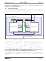
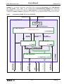
Model Description............................................................................................ 27
4.1
4.2
4.3
4.4
PROTOCOL_TESTBENCH .........................................................................................
CAN_SYSTEM .............................................................................................................
4.2.1 configuration SYS_I of CAN_SYSTEM ...........................................................
4.2.2 configuration SYS_E of CAN_SYSTEM ..........................................................
4.2.3 configuration SYS_B of CAN_SYSTEM..........................................................
4.2.4 configuration SYS_R of CAN_SYSTEM..........................................................
BUS_INTERFACE ........................................................................................................
CAN_INTERFACE .......................................................................................................
4.4.1 architecture COMPARE.....................................................................................
4.4.1.1 CHECKER ...........................................................................................
4.4.2 architecture REFERENCE .................................................................................
4.4.2.1 process OSCILLATOR........................................................................
4.4.2.2 process PRESCALER ..........................................................................
4.4.2.3 process BIT_TIMING..........................................................................
4.4.2.3.1 Overview .............................................................................
4.4.2.3.2 Structure of process BIT_TIMING .....................................
4.4.2.3.3 Synchronization ...................................................................
4.4.2.4 process BIT_STREAM_PROCESSOR ...............................................
4.4.2.4.1 Overview .............................................................................
4.4.2.4.2 Frame Format ......................................................................
4.4.2.4.3 Structure of process BIT_STREAM_PROCESSOR...........
4.4.2.5 Output to the Trace File .......................................................................
4.4.2.6 CAN Specification and Reference CAN Model ..................................
4.4.2.7 Special Features of architecture REFERENCE for Protocol Check....
iii
29
30
31
31
31
31
32
33
34
35
38
39
39
39
39
40
41
46
46
47
48
54
56
57
K8/EIS
VHDL Reference CAN
4.5
5
User’s Manual
Revision 2.2
4.4.3 architecture IMPLEMENTATION ....................................................................
4.4.4 architecture EXAMPLE .....................................................................................
4.4.4.1 architecture SIMPLE of CAN_MODULE...........................................
4.4.4.1.1 architecture BASIC of CAN_MESSAGE ...........................
4.4.4.1.2 architecture PARALLEL_16_BIT of CPU_INTERFACE .
4.4.4.1.3 architecture TIMING of CPU_CONTROL.........................
4.4.4.2 architecture READ_WRITE of CPU ...................................................
4.4.5 architecture BAD_EXAMPLE...........................................................................
TEST_PROGRAM ........................................................................................................
4.5.1 process STIMULI...............................................................................................
4.5.1.1 procedure INITIALIZE........................................................................
4.5.1.2 procedure WAIT_FOR.........................................................................
4.5.1.3 procedure SEND_MESSAGE..............................................................
4.5.1.4 procedure WRITE_TRACE .................................................................
4.5.2 process REQUEST.............................................................................................
4.5.3 process SYNCHRONIZE_REQUEST...............................................................
58
58
59
60
61
61
62
63
64
65
65
66
66
66
67
67
Verification of an Implementation................................................................. 69
5.1
5.2
5.3
5.4
Integrating an Implementation’s Model into the Reference CAN Model......................
Configuration of the Testbench......................................................................................
Adding Test programs....................................................................................................
Generating Test Vectors.................................................................................................
72
75
77
79
A-1 List of Files ..................................................................................................... 80
A-2 List of Figures ................................................................................................ 83
A-3 List of Tables.................................................................................................. 83
A-4 Related Documents ........................................................................................ 83
A-5 CAN Services.................................................................................................. 83
iv
K8/EIS
VHDL Reference CAN
1
User’s Manual
Revision 2.2
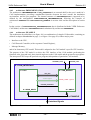
Introduction
The VHDL Reference CAN Model is intended for semiconductor designers/manufacturers who want to
build their own implementation of a CAN device using VHDL as hardware description language. It is
provided in addition to the existing C Reference CAN Model.
The user of this model is expected to be familiar with the CAN Specification Revision 2.0 Part A and B.
The model is supplied together with a testbench supporting the following features:
• CAN Protocol Version 2.0 Part A, B
• Flexible testbench environment
• Simulates entire CAN bus system (number of nodes defined by user)
• Easy inclusion of user-defined implementations
• Test program set can be extended by user
• Run time information stored in trace files
• Generation of pattern files supported
The following support is provided to assist the user in working with the model and in understanding its
functionality:
• Detailed User Manual
• Example of a correct implementation for fast start-up
• Example of a buggy implementation for the demonstration of the testbench’s functionality
• Well documented source code
This model was developed and verified with Synopsys VSS v3.4b, Mentor Graphics QuickHDL
v8.5_4.6f and with Mentor Graphics ModelSim 5.2b. A portation to other VHDL Simulators will require
an adaption of the ‘make’ files.
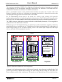
Typically a CAN implementation consists of three major parts:
• Interface to the CPU
• CAN Protocol Controller
• Message Memory
Using the test programs supplied with this VHDL Reference CAN Model only assures the conformity of
the CAN Protocol Controller part of an implementation with CAN Protocol Version 2.0 Part A, B. In
order to verify the correct function of the CPU interface and of the message memory, the user has to write
additional test programs.
-1-
K8/EIS
VHDL Reference CAN
2
User’s Manual
Revision 2.2
Installation
To install the VHDL Reference CAN Model from the CD-ROM please proceed the following way:
1)
Create a directory where you want to install the database by typing:
mkdir <path_to_model>/Bosch_CAN
Example: mkdir /projects/Bosch_CAN
2)
Copy the TAR file RefCAN_Revision_2.2.tar to this directory.
3)
Untar the database:
tar xvf RefCAN_Revision_2.2.tar
4)
Define the environment variable BOSCH_CAN_ROOT by typing:
setenv BOSCH_CAN_ROOT <path_to_model>/Bosch_CAN
The setting of the environment variable BOSCH_CAN_ROOT should be done by your project setup
procedure. Please check also that your VHDL simulator is set up correctly before proceeding.
Please check README_RefCAN.txt in your Bosch_CAN directory for additional information about
your release of the VHDL Reference CAN model.
In appendix A-1 of this document you find a list of the files and directories together with a short
description.
The VHDL Reference CAN model was developed and tested on a Sun workstation running Solaris 2.5.
If you have another hardware or operating system please contact your system manager or check the
documentation of your hardware/operating system. Up to now, the model is available for UNIX systems
only.
Simulations were done with Synopsys VSS v3.4b, Mentor Graphics QuickHDL v8.5_4.6f and Mentor
Graphics ModelSim 5.2b.
-2-
K8/EIS
VHDL Reference CAN
3
User’s Manual
Revision 2.2
Compilation and Simulation
If you have an installation of the Synopsys VSS Simulator, you can now go on with the following
commands:
cd $BOSCH_CAN_ROOT/simulate
genmake SYNOPSYS
If you have an installation of the Mentor Graphics QuickHDL Simulator proceed with the following
commands:
cd $BOSCH_CAN_ROOT/simulate
genmake MG_QuickHDL
Otherwise, if you have an installation of the Mentor Graphics ModelSim Simulator proceed with the
following commands:
cd $BOSCH_CAN_ROOT/simulate
genmake MG_ModelSim
The shell script genmake will generate the Makefile and setup files for the specified simulator in the
Bosch_CAN/simulate directory. It is used by ‘make’ to analyse the complete model. In addition to the
Makefile you will find files called Depends in the subdirectories reference, implementation,
example, buggy, tests, and tests/*. They list the dependencies of the files in these directories
and are included into the Makefile. You are now ready to run the simulations.
If you have other VHDL Simulators than Synopsys VSS, Mentor QuickHDL or Mentor ModelSim, you
can adapt the script genmake to your simulation environment or you can modify the files
Makefile.<tool> and Depends.<tool> which are distributed with this model. Additionally, you
have to provide a setup file for your simulator like .synopsys_vss_setup, quickhdl.ini or
modelsim.ini.
If you want to adapt genmake to another VHDL simulator, proceed the following way:
• Open the genmake file and copy the case statement for one of the supported simulators
and modify it to fit your simulator :
• Adapt the functions which translate the names of the compiled files to generate the names following
the rules used by your simulator.
• Adapt the command line entries used by ‘make’ to start compilation and simulation.
• Set the path for your simulator’s CAN_LIBRARY to $BOSCH_CAN_ROOT/objects.
• Add a setup file for the compiler and the simulator to $BOSCH_CAN_ROOT/simulate/.
• Add a simulation control file to $BOSCH_CAN_ROOT/simulate/.
To compile the model, please change into directory $BOSCH_CAN_ROOT/simulate/ and type make
all. This will cause the VHDL analyzer to compile the source code of the model using the information
from the files generated by genmake.
The files of compiled model can be found in the directory $BOSCH_CAN_ROOT/objects.
-3-
K8/EIS
User’s Manual
VHDL Reference CAN
3.1
Revision 2.2
Starting the Simulation
Change to the directory $BOSCH_CAN_ROOT/simulate. The simulation is started by typing make with
a specific target. The target defines the desired test program(s) to be simulated and the name of the CAN
Protocol Controller configuration to be verified. The Makefile supports three configuration names:
implementation, example, and buggy.
The following functions can be performed by make:
make clean
make all
make <test>
make <test>_e
make <test>_b
make traces
make traces_e
make traces_b
delete all binaries generated by previous runs of the VHDL analyzer
analyze the complete model
run the test program specified by <test>, linked with implementation
run the test program specified by <test>, linked with example
run the test program specified by <test>, linked with buggy
run the complete set of tests, linked with implementation
run the complete set of tests, linked with example
run the complete set of tests, linked with buggy
After the simulation of program <test> there will be a file <test>.trace in the directory
$BOSCH_CAN_ROOT/tests/<test>. This file contains the complete trace information of the
simulation run. It can be regarded as protocol and documentation of the simulation. To check whether
the installation of the model and the setup of the simulator are correct, compare the file <test>.trace,
which is generated by the simulation, with the file <test>.trace.sav, which is distributed with the
model.
The two files have to be, with one restriction, identical. The files may not be absolutely identical because
in any VHDL simulation, when several processes are triggered by the same event, the sequence of
evaluation is not predictable. For this reason the sequence of trace statements with the same time stamp
may be different when simulated with different simulation-software or -hardware. The comparison of
two trace files generated by different tools can be automated when the lines of both trace files are sorted
alphabetically. The files <test>.trace.sav have been generated by the tool Synopsys VSS v3.4b.
3.1.1
Simulating the User’s Implementation
To start the simulation of a single test for a user’s implementation model (e.g. test baudrate) type:
make baudrate
If you are simulating with Synopsys VSS, and if the simulation runs without a problem, you will see the
following messages on the screen:
vhdlsim -nc -i $BOSCH_CAN_ROOT/simulate/synopsys_sim.inc \
CAN_LIBRARY.cfg_baudrate ;
VSS_GATE_MODEL=sim_gs - for gate level simulation
"Set stop on FAILURE"
"Start simulation"
955680 NS
Assertion NOTE at 955680 NS in design unit CHECKER(BEHAVIOUR) from process \
/PROTOCOL_TESTBENCH/SYSTEM/CHECK1/PROTOCOL_CHECK/COMPARE_RX_MESSAGE:
"Received Message checked ok"
-4-
K8/EIS
VHDL Reference CAN
User’s Manual
Revision 2.2
1447710 NS
Assertion NOTE at 1447710 NS in design unit CHECKER(BEHAVIOUR) from process \
/PROTOCOL_TESTBENCH/SYSTEM/CHECK1/PROTOCOL_CHECK/COMPARE_RX_MESSAGE:
"Received Message checked ok"
3285128 NS
Assertion FAILURE at 3285128 NS in design unit TEST_PROGRAM(BAUDRATE) from \
process /PROTOCOL_TESTBENCH/WAVEFORM/STIMULI:
"End of Test Program reached: Stop Simulation !"
"Quit simulator"
mv -f trace $BOSCH_CAN_ROOT/tests/baudrate/baudrate.trace ;
if [ -s pattern ] ; then mv -f pattern $BOSCH_CAN_ROOT/tests/baudrate/. ; fi ;
The last statement of the test program is an assertion with a certain FAILURE to terminate the simulation
because this is the only way to stop a simulation that was not started with an explicit run time.
The user’s implementation model which is used here is a copy of the CAN reference model.
3.1.2
Simulating the Example of an Implementation
The example of an implementation was designed to show the user of this VHDL Reference CAN model
how to include his own implementation model into the protocol testbench. To run the simulation of a
single test for the example of an implementation model (e.g. test crc) type:
make crc_e
The trace information of this simulation run is located in file crc.e_trace
3.1.3
Simulating the Example of a Buggy Implementation
The example of a buggy implementation is identical to example of an implementation with the difference
that some faults were inserted in the CAN protocol controller part. This buggy version of a CAN
implementation demonstrates how CAN protocol error are detected.
To run the simulation of the example of a buggy implementation model (e.g. test btl) type:
make btl_b
During the simulation there will appear some messages on the screen like the one below:
3493250 NS
Assertion ERROR at 3493250 NS in design unit CHECKER(BEHAVIOUR) \
from process /PROTOCOL_TESTBENCH/SYSTEM/CHECK1/PROTOCOL_CHECK/CMP_RX:
“Protocol Error: Invalid BUSMON”
These messages will give you a hint where the problem may be located. The trace information of the
simulation run can be found in file btl.b_trace
-5-
K8/EIS
VHDL Reference CAN
3.2
User’s Manual
Revision 2.2
Test programs
The CAN protocol test programs check the behaviour of a CAN implementation by comparing them with
the behaviour of the Reference CAN Model node. Their purpose is to check whether the CAN protocol
is correctly implemented in the model of the implementation, they are by no means a production test.
The programs are not adapted to a specific implementation, the success of this test patterns is a
necessary, not a sufficient condition for the assessment of the implementation. In the following the
different waveforms are listed in alphabetical order and described in detail.
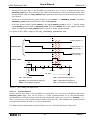
3.2.1
baudrate
Test of Prescaler and Oscillator Tolerance
NUMBER_OF_CANS:
Bit Timing:
3
Different Bit Timing for each Node
This architecture uses a system configuration with three CAN nodes. The first CAN node consists of one
implementation CAN model and one Reference CAN Model node working in parallel, the other two
nodes consist of Reference CAN Model nodes. Each node gets a different timing configuration,
depending on different clock periods. The resulting minimum and maximum bit time are in an area of
1.7% around the average bit time. In three cycles, the three nodes start the transmission of a message. In
the first cycle, the third node wins the arbitration, in the second cycle, the second node, and in the third
cycle, the first node wins the arbitration. As additional handicap, the messages transmitted are designed
to contain a maximum of stuff bits, reducing the number of edges that can be used for resynchronisation.
Those nodes losing arbitration do that immediately next to a stuff bit.
After the last transmission, when the bus is idle, the position of the sample point in the scaled bit time is
checked by applying a spike to dominant at the RECEIVE_DATA inputs of the implementation CAN
model and of the Reference CAN Model node which is running in parallel to the implementation.
As long as the spike is not longer than the sum of Propagation Delay Segment and Phase Buffer
Segment 1, the dominant bus level is not sampled. Note: Even if the spike is not sampled, it is used for
synchronisation.
3.2.2
biterror
Confinement of Bit Errors
NUMBER_OF_CANS:
Bit Timing:
2
CLOCK_PERIOD = 100 ns, PRESCALER = 1,
NTQ = 10, SAMPLE = 6, RESYCHRONIZATION_JUMP_WIDTH = 4
Transmitters and receivers get bit errors at dominant bits in all fields and all frames, transmitters get bit
errors at recessive bits in the Control, Data, and CRC Field. Tested while Error Active and Error Passive.
The program consists of the following test steps:
Test of receiver
1)
Recessive bit at ACK Slot, recessive bit at first bit of Active Error Flag.
A dominant ACK bit is forced to recessive. The receiver detects a bit error and sends an Active Error
Flag. The receive error counter is increased by 1.
The first bit of the Receiver Error Flag is forced to recessive. The receiver detects a bit error and
starts sending an Active Error Flag again. The receive error counter is increased by 8.
-6-
K8/EIS
VHDL Reference CAN
User’s Manual
Revision 2.2
2)
Recessive bit at last bit of Active Error Flag.
The last bit of an Active Error Flag is forced to recessive. The receiver detects a bit error and starts
sending an Active Error Flag again. The receive error counter is increased by 8.
3)
Dominant bit at first bit of Intermission, recessive bit at first bit of Overload Flag.
The first bit of Intermission is forced to dominant to create an Overload Flag. Then the first bit of
this Overload Flag is forced to recessive. The receiver detects a bit error and sends an Active Error
Flag. The receive error counter is increased by 8.
4)
Dominant bit at first bit of Intermission, recessive bit at last bit of Overload Flag.
The first bit of Intermission is forced to dominant to create an Overload Flag. Then the last bit of
this Overload Flag is forced to recessive. The receiver detects a bit error and sends an Active Error
Flag. The receive error counter is increased by 8.
5)
Create Active Error Flags until receiver is Error Passive.
When sending an Active Error Flag the RECEIVE_DATA input of the receiver is forced to recessive
for 11 bit times. The receiver detects bit errors at every bit and starts Active Error Flags. With every
bit error the receive error counter is increased by 8. Then the last Active Error Flag is sent and the
receiver becomes Error Passive, but it continues sending the Active Error Flag.
6)
Recessive bit at ACK Slot, dominant bit at first bit of Passive Error Flag.
A dominant ACK bit is forced to recessive. The receiver detects a bit error and sends a Passive Error
Flag. The receive error counter is increased by 1.
The first bit of the passive Receiver Error Flag is forced to dominant. The receiver detects a bit error
and starts sending a Passive Error Flag again. The receive error counter is not changed.
7)
Dominant bit at last bit of Passive Error Flag.
The last bit of a Passive Error Flag is forced to dominant. The receiver detects a bit error and starts
sending a Passive Error Flag again. The receive error counter is not changed.
8)
Dominant bit at first bit of Intermission, recessive bit at first bit of Overload Flag.
The first bit of Intermission is forced to dominant to create an Overload Flag. Then the first bit of
this Overload Flag is forced to recessive. The receiver detects a bit error and sends a Passive Error
Flag. The receive error counter is not changed.
9)
Dominant bit at first bit of Intermission, recessive bit at last bit of Overload Flag.
The first bit of Intermission is forced to dominant to create an Overload Flag. Then the last bit of
this Overload Flag is forced to recessive. The receiver detects a bit error and sends a Passive Error
Flag. The receive error counter is not changed.
Test of transmitter
1)
Recessive bit at Start of Frame.
The dominant Start of Frame bit is forced to recessive. The transmitter detects a bit error and sends
an Active Error Flag. The transmit error counter is increased by 8.
2)
Recessive bit at reserved bit, recessive bit at first bit of Active Error Flag.
A dominant reserved bit is forced to recessive. The transmitter detects a bit error and sends an Active
Error Flag. The transmit error counter is increased by 8.
The first bit of the Transmitter Error Flag is forced to recessive. The transmitter detects a bit error
and starts sending an Active Error Flag again. The transmit error counter is increased by 8.
3)
Recessive bit at last bit of Active Error Flag.
The last bit of an Active Error Flag is forced to recessive. The transmitter detects a bit error and
starts sending an Active Error Flag again. The transmit error counter is increased by 8.
-7-
K8/EIS
VHDL Reference CAN
User’s Manual
Revision 2.2
4)
Dominant bit at first bit of Intermission, recessive bit at first bit of Overload Flag.
The first bit of Intermission is forced to dominant to create an Overload Flag. Then the first bit of
this Overload Flag is forced to recessive. The transmitter detects a bit error and sends an Active
Error Flag. The transmit error counter is increased by 8.
5)
Dominant bit at first bit of Intermission, recessive bit at last bit of Overload Flag.
The first bit of Intermission is forced to dominant to create an Overload Flag. Then the last bit of
this Overload Flag is forced to recessive. The transmitter detects a bit error and sends an Active
Error Flag. The transmit error counter is increased by 8.
6)
Dominant bit at first bit of Data Length Code.
A recessive bit of Data Length Code is forced to dominant. The transmitter detects a bit error and
sends an Active Error Flag. The transmit error counter is increased by 8.
7)
Recessive bit at last bit of Data Length Code.
A dominant bit of Data Length Code is forced to recessive. The transmitter detects a bit error and
sends an Active Error Flag. The transmit error counter is increased by 8.
8)
Dominant bit at first bit of Data Field.
A recessive bit of Data Field is forced to dominant. The transmitter detects a bit error and sends an
Active Error Flag. The transmit error counter is increased by 8.
9)
Recessive bit at 8th bit of Data Field.
A dominant bit of Data Field is forced to recessive. The transmitter detects a bit error and sends an
Active Error Flag. The transmit error counter is increased by 8.
10) Dominant bit at first bit of CRC Field.
A recessive bit of CRC Field is forced to dominant. The transmitter detects a bit error and sends an
Active Error Flag. The transmit error counter is increased by 8.
11) Recessive bit at last bit of CRC Field.
A dominant bit of CRC Field is forced to recessive. The transmitter detects a bit error and sends an
Active Error Flag. The transmit error counter is increased by 8.
12) Create Active Error Flags until transmitter is Error Passive.
When sending an Active Error Flag the RECEIVE_DATA input of the transmitter is forced to
recessive for 3 bit times. The transmitter detects bit errors at every bit and starts Active Error Flags.
With every bit error the transmit error counter is increased by 8. Then the last Active Error Flag is
sent and the transmitter becomes Error Passive, but it continues sending the Active Error Flag.
13) Recessive bit at Start of Frame.
The dominant Start of Frame bit is forced to recessive. The transmitter detects a bit error and sends
a Passive Error Flag. The transmit error counter is increased by 8.
14) Recessive bit at reserved bit, dominant bit at first bit of Passive Error Flag.
A dominant reserved bit is forced to recessive. The transmitter detects a bit error and sends a Passive
Error Flag. The transmit error counter is increased by 8.
The first bit of the passive Transmitter Error Flag is forced to dominant. The transmitter detects a
bit error and starts sending a Passive Error Flag again. The transmit error counter is not changed.
15) Dominant bit at last bit of Passive Error Flag.
The last bit of a Passive Error Flag is forced to dominant. The transmitter detects a bit error and starts
sending a Passive Error Flag again. The receive error counter is not changed.
-8-
K8/EIS
VHDL Reference CAN
User’s Manual
Revision 2.2
16) Dominant bit at first bit of Intermission, recessive bit at first bit of Overload Flag.
The first bit of Intermission is forced to dominant to create an Overload Flag. Then the first bit of
this Overload Flag is forced to recessive. The transmitter detects a bit error and sends a Passive Error
Flag. The transmit error counter is increased by 8.
17) Dominant bit at first bit of Intermission, recessive bit at last bit of Overload Flag.
The first bit of Intermission is forced to dominant to create an Overload Flag. Then the last bit of
this Overload Flag is forced to recessive. The transmitter detects a bit error and sends a Passive Error
Flag. The transmit error counter is increased by 8.
18) Dominant bit at first bit of Data Length Code.
A recessive bit of Data Length Code is forced to dominant. The transmitter detects a bit error and
sends a Passive Error Flag. The transmit error counter is increased by 8.
19) Recessive bit at last bit of Data Length Code.
A dominant bit of Data Length Code is forced to recessive. The transmitter detects a bit error and
sends a Passive Error Flag. The transmit error counter is increased by 8.
20) Dominant bit at first bit of Data Field.
A recessive bit of Data Field is forced to dominant. The transmitter detects a bit error and sends a
Passive Error Flag. The transmit error counter is increased by 8.
21) Recessive bit at 8th bit of Data Field.
A dominant bit of Data Field is forced to recessive. The transmitter detects a bit error and sends a
Passive Error Flag. The transmit error counter is increased by 8.
22) Dominant bit at first bit of CRC Field.
A recessive bit of CRC Field is forced to dominant. The transmitter detects a bit error and sends a
Passive Error Flag. The transmit error counter is increased by 8.
23) Recessive bit at last bit of CRC Field.
A dominant bit of CRC Field is forced to recessive. The transmitter detects a bit error and sends a
Passive Error Flag. The transmit error counter is increased by 8.
3.2.3
btl
Bit Timing
NUMBER_OF_CANS:
Bit Timing:
1
CLOCK_PERIOD = 100 ns, PRESCALER = 1,
To test Hard Synchronization and Resynchronization, an edge from recessive to dominant is generated
for each time quanta of a bit time. The case of an edge immediately before the sample point is excluded.
The program runs three configurations of the bit timing:
1) Large Phase Buffer, Large Synchronization Jump Width
NTQ = 10, SAMPLE = 6, RESYCHRONIZATION_JUMP_WIDDTH = 4
2) Large Phase Buffer, Small Synchronization Jump Width
NTQ = 25, SAMPLE = 17, RESYCHRONIZATION_JUMP_WIDDTH = 1
3) Small Phase Buffer, Small Synchronization Jump Width
NTQ = 10, SAMPLE = 8, RESYCHRONIZATION_JUMP_WIDDTH = 1
-9-
K8/EIS
VHDL Reference CAN
User’s Manual
Revision 2.2
With each configuration of the bit timing the following tests are performed:
a) Hard Synchronization, TX_DATA = Recessive, not Transmitter, not Receiver
b) Resychronization, TX_DATA = Recessive, Receiver
c) Resychronization, TX_DATA = Dominant, Receiver
d) Resychronization, TX_DATA = Dominant, Transmitter
e) Resychronization, TX_DATA = Recessive, Transmitter
f) Hard Synchronization, TX_DATA = Dominant, Transmitter
Note: The edges from recessive to dominant on the RECEIVE_DATA input which are used for Hard
Synchronization and Resynchronization appear with the falling edge of TIME_QUANTA_CLOCK while
synchronization is started with the rising edge of TIME_QUANTA_CLOCK.
3.2.4
crc
Cyclic Redundancy Check and Acknowledge
NUMBER_OF_CANS:
Bit Timing:
2
CLOCK_PERIOD = 100 ns, PRESCALER = 1,
NTQ = 10, SAMPLE = 6, RESYCHRONIZATION_JUMP_WIDTH = 4
Test of receiver’s error detection in case of Bit Error in the Data Field and in the CRC Field and test of
the transmitter’s reaction on acknowledge errors.
The program consists of the following test steps:
Test of receiver
1)
Recessive bit at reserved bit r0.
The dominant bit at r0 is forced to recessive. The receiver detects a CRC error, sends a recessive
ACK bit and an Active Error Flag after the ACK Delimiter. The receive error counter is increased
by 1.
2)
Dominant bit at the 2nd bit of CRC Field.
The recessive bit of CRC Field is forced to dominant. The receiver detects a CRC error, sends a
recessive ACK bit and an Active Error Flag after the ACK Delimiter. The receive error counter is
increased by 1. The receiver detects a dominant bit after sending its Error Flag and increases its error
counter by 8.
Test of transmitter
1)
Recessive bit at ACK Slot, RECEIVE_DATA input of RefCAN2 is forced to recessive.
The bus state of RefCAN2 is idle, because the RECEIVE_DATA input is forced to recessive. The
transmitter (RefCAN1) detects an ACK error and sends an Active Error Flag. The transmit error
counter is increased by 8.
2)
Recessive bits after 2nd bit of Active Error Flag until transmitter is Error Passive, RECEIVE_DATA
input of RefCAN2 is forced to recessive.
During sending an Active Error Flag the RECEIVE_DATA input of the transmitter is forced to
recessive for 14 bit times. The transmitter detects bit errors at every bit and starts Active Error Flags.
- 10 -
K8/EIS
VHDL Reference CAN
User’s Manual
Revision 2.2
With every bit error the transmit error counter is increased by 8. Then the last Active Error Flag is
sent and the transmitter becomes Error Passive (TEN 120 -> 128), but it continues sending the
Active Error Flag.
3)
Recessive bit at ACK Slot, no dominant bit during Passive Error Flag, RECEIVE_DATA input of
RefCAN2 is forced to recessive.
The bus state of RefCAN2 is idle, because the RECEIVE_DATA input is forced to recessive. The
transmitter (RefCAN1) detects an ACK error and sends a Passive Error Flag. During the Passive
Error Flag no dominant bit appears on the bus. The transmit error counter is not changed.
4)
Transmitting a frame successful, transmitter is Error Active.
The transmitter transmits a frame without errors. The transmit error counter is decreased by 1
(TEC = 127).
5)
Recessive bit at 2nd bit of Identifier.
The dominant bit of Identifier is forced to recessive. The transmitter detects a bit error and sends an
Active Error Flag. The transmit error counter is increased by 8. Transmitter is Error Passive.
6)
Recessive bit at ACK Slot, dominant bits after Passive Error Flag, RECEIVE_DATA input of
RefCAN2 is forced to recessive.
The bus state of RefCAN2 is Idle, because the RECEIVE_DATA input is forced to recessive. The
transmitter (RefCAN1) detects an ACK error and sends a Passive Error Flag. During the Passive
Error Flag no dominant bit appears on the bus. The transmit error counter is not changed. After
Passive Error Flag the RECEIVE_DATA input of RefCAN1 is forced to dominant for 113 bit times.
The transmitter detects form errors at every 8th bit and increases its error counter by 8 (TEC = 247).
7)
Recessive bit at ACK Slot, dominant bit at the 2nd bit of Passive Error Flag, RECEIVE_DATA input
of RefCAN2 is forced to recessive.
The bus state of RefCAN2 is Idle, because the RECEIVE_DATA input is forced to recessive. The
transmitter (RefCAN1) detects an ACK error and sends a Passive Error Flag. During the Passive
Error Flag a dominant bit appears on the bus. The transmit error counter is increased by 8
(TEC = 255).
8)
Recessive bit at ACK Slot, dominant bit at the 6th bit of Passive Error Flag, RECEIVE_DATA input
of RefCAN2 is forced to recessive.
The bus state of RefCAN2 is Idle, because the RECEIVE_DATA input is forced to recessive. The
transmitter (RefCAN1) detects an ACK error and sends a Passive Error Flag. During the Passive
Error Flag a dominant bit appears on the bus. The transmit error counter is increased by 8
(TEC = 263) and the transmitter becomes Bus Off.
3.2.5
dlc
Data Field Length
NUMBER_OF_CANS:
Bit Timing:
2
CLOCK_PERIOD = 100 ns, PRESCALER = 1,
NTQ = 10, SAMPLE = 6, RESYCHRONIZATION_JUMP_WIDTH = 4
Reception and transmission of messages with all possible (0 … 15 !) Data Length Codes as Data and as
Remote Frames. In the first part of the test, the receiver (RefCAN1) receives all 32 messages. In the
second part, the transmitter (RefCAN1) transmits all 32 messages.
- 11 -
K8/EIS
VHDL Reference CAN
3.2.6
User’s Manual
Revision 2.2
emlcount
Function of Error Management Logic, -Counters, and -States
NUMBER_OF_CANS:
Bit Timing:
2
CLOCK_PERIOD = 100 ns, PRESCALER = 1,
NTQ = 10, SAMPLE = 6, RESYCHRONIZATION_JUMP_WIDTH = 2
Receive and transmit error counters are incremented and decremented around the Error Warning Limit,
the Error Passive Limit and the Bus Off Limit. The fault confinement in case of stuck-at-dominant after
sending an Error Flag is tested.
The program consists of the following test steps:
Test of receiver
1)
Stuff error at stuff bit after 4th bit of Identifier.
A recessive stuff bit is forced to dominant. The receiver detects a stuff error and sends an Active
Error Flag. The receive error counter is increased by 1. The receiver detects dominant bits after
sending its Error Flag and increases its error counter by 8.
2)
Dominant bit at CRC Delimiter, some resynchronisations.
The recessive CRC Delimiter bit is forced to dominant. The receiver detects a form error and sends
an Active Error Flag. The receive error counter is increased by 1. The receiver detects dominant bits
after sending its Error Flag and increases its error counter by 8. While waiting for the CRC
Delimiter, some resynchronisations are tested by generating positive and negative phase errors at
edges from recessive to dominant.
3)
Recessive bit at ACK Slot.
The dominant ACK bit is forced to recessive. The receiver detects a bit error and sends an Active
Error Flag. The receive error counter is increased by 1. The receiver detects dominant bits after
sending its Error Flag and increases its error counter by 8.
4)
Dominant bit at last bit of End of Frame, 7 dominant bits after Overload Flag.
The recessive bit of End of Frame is forced to dominant. The RECEIVE_DATA input is forced to
dominant for another 13 bits. The receiver detects an overload condition and sends an Overload
Frame. After sending the Overload Frame the receiver detects 7 dominant bits before sending the
Overload Delimiter. The receive error counter is not changed.
5)
Dominant bit at last bit of Overload Delimiter.
The recessive bit of Overload Delimiter is forced to dominant. The receiver starts sending an
Overload Flag. The receive error counter is not changed.
6)
Recessive bit at first bit of Overload Flag, recessive bit at Active Error Flag, increment the REC to
106. The dominant Overload Flag is forced to recessive. The receiver detects a bit error and sends
an Active Error Flag. The receive error counter is increased by 8. Some bits of the following Active
Error Flags are forced to recessive, therefore the Error Flags start again and increases the receive
error counter by 8.
7)
Wait until Intermission and receive new frame, REC=105.
The receiver waits for the last bit of Intermission and receives a new frame successful. The receive
error counter is decreased by 1.
- 12 -
K8/EIS
VHDL Reference CAN
User’s Manual
Revision 2.2
8)
Wait until Intermission and receive new frame, REC=104.
The receiver waits for the last bit of Intermission and receives a new frame successful. The receive
error counter is decreased by 1.
9)
Wait until Intermission and receive new frame, REC=103.
The receiver waits for the last bit of Intermission and receives a new frame successful. The receive
error counter is decreased by 1.
10) Dominant bit at last bit of End of Frame, 4 * 8 dominant bits after Overload Flag.
The recessive bit of End of Frame is forced to dominant. The RECEIVE_DATA input is forced to
dominant for another 38 bits. The receiver detects a form error and sends an Overload Flag. After
sending the Overload Flag the receiver detects 8 dominant bits and increases its error counter by 8.
After each sequence of additional eight consecutive dominant bits the receive error counter is
increased by 8. Receiver is now Error Passive.
11) Dominant bit at the 3rd bit of Overload Delimiter, 8 * 2 dominant bits after Passive Error Flag.
A recessive bit of Overload Delimiter is forced to dominant. The receiver detects a form error and
sends a Passive Error Flag. The receive error counter is increased by 1 and its now equal to 136.
Then the next 16 bit after the Error Flag are forced to dominant. The receiver continues sending
Passive Error Flag. After each sequence of eight consecutive dominant bits normally the receive
error counter is increased by eight, however the counter is equal to 136 and not increased.
12) Receive correct frame, REC ~ [119 … 127].
The receiver waits for the last bit of Intermission and receives a new frame.
13) Wait until End of Frame, node Error Active again.
After the successful reception the receive error counter is decremented. The receiver is now Error
Active.
14) Receive correct frame, REC = REC - 1.
After the successful reception the receive error counter is decreased by 1.
15) Dominant bit at the first bit of Intermission, recessive bit at the first bit of Overload Flag and Error
Flag. The recessive bit of Intermission is forced to dominant. The receiver detects an overload
condition and sends an Overload Flag. Then the first bit of Overload Flag is forced to recessive. The
receiver detects a bit error and sends an Error Flag. The receive error counter is increased by 8.
Depending on the value of the REC after finishing Error Passive, the actual REC value is above 127
or below 128. Nevertheless, an Active Error Flag is sent. The first bit of the Active Error Flag is
forced to dominant, setting the node to Error Passive.
16) Receive correct frame, REC ~ [119 … 127].
The receiver waits for the last bit of Intermission and receives a new frame. After the successful
reception the receive error counter is set to below 128.
17) Receiver sees local bit error in CRC_Field.
One bit of the received message is falsified, causing a CRC-Error.
18) Receiver with CRC-Error sees foreign dominant Acknowledge => Rec+/-0.
Node does not send a dominant Acknowledge, but samples a dominant bit in the Acknowledge Slot.
19) Receiver starts CRC-Error-Flag, REC = REC+1.
Active Error Flag is started after Acknowledge Delimiter because of CRC-Error.
20) Recessive Bit in Error Flag => Error Passive.
A bit Error in Active Error Flag sets the node to Error Passive.
- 13 -
K8/EIS
VHDL Reference CAN
User’s Manual
Revision 2.2
Test of transmitter
1)
Error Passive Transmitter with TEC < 128 sees Bit Error at dominant Identifier bit.
Node sends Passive Error Flag and adds Suspend to Interframe Space.
2)
Error Passive Transmitter sees 104 consecutive dominant bits after Passive Error Flag.
Transmit error counter is incremented to 120.
3)
Receive error counter is decremented by reception of correct messages.
Node is Error Active.
4)
transmit error counter is incremented to 128.
Node is Error Passive.
5)
Receiver sees Stuff Error and 16 consecutive dominant bits after Error Flag.
Receive error counter is incremented to 135.
6)
One Successful transmission, then Bit Error at dominant Identifier bit.
Transmit error counter is decremented to 127, then Passive Error Flag.
A hardware reset is performed, both error counters are reset to 0.
7)
Recessive bit at Start of Frame.
The dominant Start of Frame bit is forced to recessive. The transmitter detects a bit error and sends
an Active Error Flag. The transmit error counter is increased by 8.
8)
Dominant bit at ACK Delimiter.
The recessive ACK Delimiter bit is forced to dominant. The transmitter detects a bit error and sends
an Active Error Flag. The transmit error counter is increased by 8.
9)
Dominant bit at the first bit of End of Frame.
The recessive bit of End of Frame is forced to dominant. The transmitter detects a bit error and sends
an Active Error Flag. The transmit error counter is increased by 8.
10) Dominant bit at the last bit of End of Frame.
The recessive bit of End of Frame is forced to dominant. The transmitter detects a bit error and sends
an Active Error Flag. The transmit error counter is increased by 8
11) Dominant bit at last bit of Error Delimiter, 7 dominant bits after Overload Flag.
The last recessive bit of Error Delimiter is forced to dominant. The transmitter detects an overload
condition and sends an Overload Frame. After sending the Overload Frame the transmitter detects
7 consecutive dominant bits before sending the Overload Delimiter. The transmit error counter is
not changed.
12) Dominant bit at last bit of Overload Delimiter, 8 dominant bits after Overload Flag.
The recessive bit of Overload Delimiter is forced to dominant. The transmitter detects an overload
condition and sends an Overload Frame. After sending the Overload Frame the transmitter detects
8 consecutive dominant bits before sending the Overload Delimiter. The transmit error counter is
increased by 8.
13) Dominant bit at the 2nd bit of Overload Delimiter.
The recessive bit of Overload Delimiter is forced to dominant. The transmitter detects a bit error and
sends an Active Error Flag. The transmit error counter is increased by 8.
14) Dominant bit at the 2nd bit of Error Delimiter.
The recessive bit of Error Delimiter is forced to dominant. The transmitter detects a bit error and
sends an Active Error Flag. The transmit error counter is increased by 8.
- 14 -
K8/EIS
VHDL Reference CAN
User’s Manual
Revision 2.2
15) Recessive bit at ACK Slot, 8 * 4 dominant bits after Error Flag
The dominant ACK bit is forced to recessive. The transmitter detects an ACK error and sends an
Active Error Flag. The transmit error counter is increased by 8. After the Error Flag the
RECEIVE_DATA input is forced to dominant for another 32 bits. After each sequence of additional
eight consecutive dominant bits the transmitter detects a form error and increases the error counter
by 8.
16) Dominant bit at 2nd bit of Intermission, recessive bit at first bit of Overload and Error Flag.
The recessive bit of Intermission is forced to dominant. The transmitter detects an overload
condition and sends an Overload Frame. Then the first bit of the Overload Flag is forced to
dominant. The transmitter detects a bit error and sends an Active Error Flag. The transmit error
counter is increased by 8.
During sending an Active Error Flag the RECEIVE_DATA input of the transmitter is forced to
recessive for 3 bit times. The transmitter detects bit errors at every bit and starts Active Error Flags.
With every bit error the transmit error counter is increased by 8. Then at the beginning of the last
Active Error Flag the transmitter becomes Error Passive, but it continues sending the Active Error
Flag.
17) Send 7 messages decrementing TEC to 128.
The transmitter sends 7 messages. After the successful transmission of each message the transmit
error counter is decreased by 1.
18) Error Passive transmitter sees Stuff Error during Arbitration at recessive stuff bit.
No TEC change on arbitration stuff error
19) Send one successful message.
Node is set back to Error Active.
20) Recessive bit at Start of Frame.
The dominant Start of Frame bit is forced to recessive. The transmitter detects a bit error and sends
an Active Error Flag. The transmit error counter is increased by 8. The transmitter is now Error
Passive again.
21) Recessive bit at Start of Frame (Error Passive).
The dominant Start of Frame bit is forced to recessive. The transmitter detects a bit error and sends
a Passive Error Flag. The transmit error counter is increased by 8.
22) Dominant bit at ACK Delimiter (Error Passive).
The recessive ACK Delimiter bit is forced to dominant. The transmitter detects a bit error and sends
a Passive Error Flag. The transmit error counter is increased by 8.
23) Dominant bit at the first bit of End of Frame (Error Passive).
The recessive bit of End of Frame is forced to dominant. The RECEIVE_DATA input is forced to
dominant for another 6 bits. The transmitter detects a bit error (at End of Frame) and sends a Passive
Error Flag. The transmit error counter is increased by 8. The 6 dominant bits during the Passive
Error Flag have no effect.
24) Dominant bit at the last bit of End of Frame (Error Passive), bit error during Passive Error Flag.
The recessive bit of End of Frame is forced to dominant. The transmitter detects a bit error and sends
a Passive Error Flag. The transmit error counter is increased by 8. Then the 3rd bit of Passive Error
Flag is forced to dominant. The transmitter continues sending Passive Error Flag and waits again
for 6 consecutive bits without changing the error counter.
- 15 -
K8/EIS
VHDL Reference CAN
User’s Manual
Revision 2.2
25) Dominant bit at last bit of Error Delimiter (Error Passive), 7 dominant bits after Overload Flag.
The last recessive bit of Error Delimiter is forced to dominant. The transmitter detects an overload
condition and sends an Overload Frame. After sending the Overload Frame the transmitter detects
7 consecutive dominant bits before sending the Overload Delimiter. The transmit error counter is
not changed.
26) Dominant bit at last bit of Overload Delimiter (Error Passive), 8 dominant bits after Overload Flag.
The recessive bit of Overload Delimiter is forced to dominant. The transmitter detects an overload
condition and sends an Overload Frame. After sending the Overload Frame the transmitter detects
8 consecutive dominant bits before sending the Overload Delimiter. The transmit error counter is
increased by 8.
27) Dominant bit at the 2nd bit of Overload Delimiter (Error Passive).
The recessive bit of Overload Delimiter is forced to dominant. The transmitter detects a bit error and
sends a Passive Error Flag. The transmit error counter is increased by 8.
28) Recessive bit at ACK Slot (Error Passive)
The dominant ACK bit is forced to recessive. The transmitter detects an ACK error and sends a
Passive Error Flag. The transmit error counter is not changed because it does not detect a dominant
bit while sending its Passive Error Flag.
29) 2nd bit of Error Delimiter forced dominant (Error Passive), 64 dominant bits after Passive Error
Flag.
The recessive bit of Error Delimiter is forced to dominant. The transmitter detects a bit error and
sends a Passive Error Flag. The transmit error counter is increased by 8.
After the Error Flag the RECEIVE_DATA input is forced to dominant for another 64 bits. After each
sequence of additional eight consecutive dominant bits the transmitter detects a form error and
increases the error counter by 8.
30) Dominant bit at last bit of Error Delimiter (Error Passive).
The last recessive bit of Error Delimiter is forced to dominant. The transmitter detects an overload
condition and sends an Overload Frame.
31) Dominant bit at 3rd bit of Intermission (Error Passive).
The last bit of Intermission is forced to dominant. The node is Error Passive and becomes receiver.
The next 5 bits are also forced to dominant. The receiver detects a stuff error and sends a Passive
Error Flag. The receive error counter is incremented by 1.
32) Dominant bit at the first bit after receiver’s Passive Error Flag.
The first bit after the Passive Error Flag is forced to dominant. The receiver increments the receive
error counter by 8.
33) Dominant bit at receiver’s Error Delimiter (Error Passive).
The 4th bit of Error Delimiter is forced to dominant. The receiver detects a form error and
increments the receive error counter by 1.
34) Dominant bit at the first bit after receiver’s Passive Error Flag.
The first bit after 6 consecutive recessive Passive Error Flag bits is forced to dominant. The receiver
increments the receive error counter by 8.
35) Dominant bit at receiver's Error Delimiter. Dominant bit after Passive Error Flag seen as dominant.
The recessive bit of Error Delimiter is forced to dominant. The receiver detects a form error and
increments the receive error counter by 1. After the 6 consecutive dominant Passive Error Flag bits
the receiver sees another dominant bit and increments the receive error counter by 8. A new
transmission is started.
- 16 -
K8/EIS
VHDL Reference CAN
User’s Manual
Revision 2.2
36) Dominant bit at first bit of transmitter's Intermission.
The recessive bit of Intermission is forced to dominant. The transmitter detects an overload
condition and sends an Overload Flag.
37) Recessive bit during transmitter's Overload Flag.
The second bit of the Overload Flag is forced to recessive. The transmitter detects a bit error and
increments its error counter by 8. Now the transmit error counter exceeds 255 and the node becomes
Bus Off.
3.2.7
extd_id
Test of proper recognition of IDE bit at all stuff conditions and test of losing arbitration at IDE bit.
NUMBER_OF_CANS:
Bit Timing:
2
CLOCK_PERIOD = 100 ns, PRESCALER = 1,
NTQ = 10, SAMPLE = 6, RESYCHRONIZATION_JUMP_WIDTH = 4
The program consists of the following test steps:
Receiver, test of stuff bit combinations at IDE
1)
IDE = dominant, standard frame: Dominant stuff bit before IDE, bit after IDE is dominant.
2)
IDE = dominant, standard frame: Dominant stuff bit before IDE, bit after IDE is recessive.
3)
IDE = dominant, standard frame: Recessive stuff bit before IDE, bit after IDE is dominant.
4)
IDE = dominant, standard frame: Recessive stuff bit before IDE, bit after IDE is recessive.
5)
IDE = dominant, standard frame: Recessive stuff bit after IDE.
6)
IDE = recessive, extended frame: Dominant stuff bit after IDE.
7)
IDE = recessive, extended frame: Dominant stuff bit before IDE, bit after IDE is dominant.
8)
IDE = recessive, extended frame: Dominant stuff bit before IDE, bit after IDE is recessive.
9)
IDE = recessive, extended frame: Illegal (dominant) SRR bit, recessive stuff bit before IDE, bit after
IDE is dominant.
10) IDE = recessive, extended frame: Illegal (dominant) SRR bit, recessive stuff bit before IDE, bit after
IDE is recessive.
Transmitter, test of stuff bit combinations at IDE
1)
IDE = dominant, standard frame: Dominant stuff bit before IDE, bit after IDE is dominant.
2)
IDE = dominant, standard frame: Recessive stuff bit before IDE, bit after IDE is dominant.
3)
IDE = dominant, standard frame: Recessive stuff bit after IDE.
4)
IDE = recessive, extended frame: Dominant stuff bit after IDE.
5)
IDE = recessive, extended frame: Dominant stuff bit before IDE, bit after IDE is dominant.
6)
IDE = recessive, extended frame: Dominant stuff bit before IDE, bit after IDE is recessive.
Transmitter, test of losing arbitration before, at and after IDE
1)
IDE = dominant, standard frame: Lost arbitration at RTR (standard data frame).
- 17 -
K8/EIS
VHDL Reference CAN
User’s Manual
Revision 2.2
2)
IDE = dominant, standard frame: Lost arbitration at RTR (extended data frame with illegal SRR =
dominant).
3)
IDE = recessive, extended frame: Lost arbitration at SRR (standard data frame).
4)
IDE = recessive, extended frame: Lost arbitration at IDE (standard remote frame).
5)
IDE = recessive, extended frame: Lost arbitration at extended Identifier.
6)
IDE = recessive, extended frame: Lost arbitration at RTR (extended data frame).
7)
IDE = recessive, extended frame: Lost arbitration at SRR (extended data frame with illegal SRR =
dominant).
3.2.8
formerr
Confinement of Form Errors
NUMBER_OF_CANS:
Bit Timing:
2
CLOCK_PERIOD = 100 ns, PRESCALER = 1,
NTQ = 10, SAMPLE = 6, RESYCHRONIZATION_JUMP_WIDTH = 4
Transmitters and receivers get form errors at all fixed format fields of all frames. Tested while Error
Active and Error Passive.
The program consists of the following test steps:
Test of receiver
1)
Dominant bit at CRC Delimiter.
The recessive bit of CRC Delimiter is forced to dominant. The receiver detects a form error and
sends an Active Error Flag. The receive error counter is increased by 1. The receiver detects dominant bits after sending its Error Flag and increases its error counter by 8.
2)
Dominant bit at ACK Delimiter.
The recessive bit of ACK Delimiter is forced to dominant. The receiver detects a form error and
sends an Active Error Flag. The receive error counter is increased by 1. The receiver detects
dominant bits after sending its Error Flag and increases its error counter by 8.
3)
Dominant bit at the first bit of End of Frame.
The recessive bit of End of Frame is forced to dominant. The receiver detects a form error and sends
an Active Error Flag. The receive error counter is increased by 1. The receiver detects dominant bits
after sending its Error Flag and increases its error counter by 8.
4)
Dominant bit at the last bit of End of Frame.
The recessive bit of End of Frame is forced to dominant. The receiver detects an overload condition
and sends an Overload Flag. The receive error counter is not changed.
5)
Dominant bit at the last bit of Overload Delimiter.
The recessive bit of Overload Delimiter is forced to dominant. The receiver detects an overload
condition and sends an Overload Flag. The receive error counter is not changed.
6)
Dominant bit at the second bit of Overload Delimiter.
The recessive bit of Overload Delimiter is forced to dominant. The receiver detects a form error and
sends an Active Error Flag. The receive error counter is increased by 1. The receiver detects
dominant bits after sending its Error Flag and increases its error counter by 8.
- 18 -
K8/EIS
VHDL Reference CAN
User’s Manual
Revision 2.2
7)
Dominant bit at the second bit of Error Delimiter.
The recessive bit of Error Delimiter is forced to dominant. The receiver detects a form error and
sends an Active Error Flag. The receive error counter is increased by 1. The receiver detects
dominant bits after sending its Error Flag and increases its error counter by 8.
8)
Dominant bit at the last bit of Error Delimiter.
The recessive bit of Error Delimiter is forced to dominant. The receiver detects an overload
condition and sends an Overload Flag. The receive error counter is not changed.
9)
Dominant bit at the 8th bit after Overload Flag.
The next 16 bits after Overload Flag are forced to dominant. At the 8th and the 16th bit the receiver
detects form errors and increases its error counter by 8.
10) Dominant bit at the second bit of Overload Delimiter.
The recessive bit of Overload Delimiter is forced to dominant. The receiver detects a form error and
sends an Active Error Flag. The receive error counter is increased by 1. The receiver detects
dominant bits after sending its Error Flag and increases its error counter by 8.
11) Dominant bit at the 8th bit after Active Error Flag.
The next 16 bits after Active Error Flag are forced to dominant. At the 8th and the 16th bit the
receiver detects form errors and increases its error counter by 8.
Test of transmitter
1)
Dominant bit at CRC Delimiter.
The recessive bit of CRC Delimiter is forced to dominant. The transmitter detects a form error and
sends an Active Error Flag. The transmit error counter is increased by 8.
2)
Dominant bit at ACK Delimiter.
The recessive bit of ACK Delimiter is forced to dominant. The transmitter detects a form error and
sends an Active Error Flag. The transmit error counter is increased by 8.
3)
Dominant bit at the first bit of End of Frame.
The recessive bit of End of Frame is forced to dominant. The transmitter detects a form error and
sends an Active Error Flag. The transmit error counter is increased by 8.
4)
Dominant bit at the last bit of End of Frame.
The recessive bit of End of Frame is forced to dominant. The transmitter detects a form error and
sends an Active Error Flag. The transmit error counter is increased by 8.
5)
Dominant bit at the last bit of Error Delimiter.
The recessive bit of Error Delimiter is forced to dominant. The transmitter detects an overload
condition and sends an Overload Frame. The transmit error counter is not changed.
6)
Dominant bit at the last bit of Overload Delimiter.
The recessive bit of Overload Delimiter is forced to dominant. The transmitter detects an overload
condition and sends an Overload Frame. The transmit error counter is not changed.
7)
Dominant bit at the second bit of Overload Delimiter.
The recessive bit of Overload Delimiter is forced to dominant. The transmitter detects a form error
and sends an Active Error Flag. The transmit error counter is increased by 8.
8)
Dominant bit at the second bit of Error Delimiter.
The recessive bit of Error Delimiter is forced to dominant. The transmitter detects a form error and
sends an Active Error Flag. The transmit error counter is increased by 8.
- 19 -
K8/EIS
VHDL Reference CAN
9)
User’s Manual
Revision 2.2
Dominant bit at the 8th bit after Overload Flag.
The next 16 bits after Overload Flag are forced to dominant. At the 8th and the 16th bit the
transmitter detects form errors and increases its error counter by 8.
10) Dominant bit at the 8th bit after Active Error Flag.
The next 16 bits after Active Error Flag are forced to dominant. At the 8th and the 16th bit the
transmitter detects form errors and increases its error counter by 8.
3.2.9
idle
Reset and BusOff Recovery Sequences
NUMBER_OF_CANS:
Bit Timing:
1
CLOCK_PERIOD = 100 ns, PRESCALER = 1,
NTQ = 10, SAMPLE = 8, RESYCHRONIZATION_JUMP_WIDTH = 1
The reset (11 consecutive recessive bits) and Bus Off (at least 128 * 11 consecutive recessive bits)
recovery sequences are tested by setting dominant bits at interesting positions of that sequences. The
detection of Start of Frame is checked; the behaviour of the error counters is monitored.
The program consists of the following test steps:
1)
Dominant bit at the 9th bit of Wait_For_Bus_Idle.
The recessive 9th bit of Wait_For_Bus_Idle is forced to dominant. The Wait_For_Bus_Idle cycle
starts again.
2)
Dominant bit at the 11th bit of Wait_For_Bus_Idle.
The recessive 11th bit of Wait_For_Bus_Idle is forced to dominant. The Wait_For_Bus_Idle cycle
starts again.
3)
Dominant bit at the second bit of Bus_Idle field.
A recessive bit during Bus Idle is forced to dominant. The node interprets this as Start of Frame and
becomes receiver. After the 6th bit of Identifier the receiver detects a stuff error and sends an Active
Error Flag. The receive error counter is increased by 1.
4)
Dominant bit at the 3rd bit of Intermission.
The recessive 3rd bit of Intermission is forced to dominant. The node interprets this as Start of
Frame and becomes transmitter.
5)
Sending Active Error Flags, Passive Error Flag until suspend is reached.
When sending an Active Error Flag the RECEIVE_DATA input is forced to recessive. The transmitter
detects bit errors and increases its error counter with every bit error by 8 until the node is Error
Passive. After the Passive Error Flag, Error Delimiter and Intermission the transmitter sends
Suspend Transmission.
6)
Recessive bit at the 2nd bit of Identifier.
The dominant 2nd bit of Identifier is forced to recessive. The transmitter detects a bit error and sends
a Passive Error Flag. The transmit error counter is increased by 8.
7)
Waiting for Bus Off.
The RECEIVE_DATA input is forced to recessive. The transmitter detects bit errors at every Start of
Frame bit and sends Passive Error Flags. With every error the transmit error counter is increased by
8. If the error counter is > 255 the node becomes Bus Off.
- 20 -
K8/EIS
VHDL Reference CAN
User’s Manual
Revision 2.2
8)
Abort transmission.
The reset_transmission_request is set to abort the transmission. The node waits now for 128 * 11
consecutive recessive bits.
9)
Dominant bit at the 9th position of Bus Off recovery sequence.
The recessive 9th bit of Bus Off recovery is forced to dominant. The recovery sequence starts again.
10) Dominant bit at the 11th position of Bus Off recovery sequence.
The recessive 11th bit of Bus Off recovery is forced to dominant. The recovery sequence starts
again.
11) Dominant bit at the first position of Bus Off recovery sequence.
The recessive 1st bit of Bus Off recovery is forced to dominant. The recovery sequence starts again.
The recovery counter is unchanged.
12) Dominant bit at the (10 + (126 * 11) ) position of Bus Off recovery.
The recessive bit of Bus Off recovery is forced to dominant. The recovery sequence starts again.
The recovery counter is unchanged. After the next 11 recessive bits the node becomes Bus Idle and
Error Active.
13) Dominant bit at the 12th position of Bus_Idle.
A recessive 12th bit during Bus Idle is forced to dominant. The node interprets this as Start of Frame
and becomes receiver. After the 6th bit of Identifier the receiver detects a stuff error and sends an
Active Error Flag. The receive error counter is increased by 1.
3.2.10
overload
Overload Confinement
NUMBER_OF_CANS:
Bit Timing:
2
CLOCK_PERIOD = 100 ns, PRESCALER = 1,
NTQ = 10, SAMPLE = 6, RESYCHRONIZATION_JUMP_WIDTH = 4
For receivers and transmitters, dominant bits are generated at each position of Intermission, at the end of
Error Delimiter and at the last bit of a receiver’s End of Frame.
The program consists of the following test steps:
Test of receiver
1)
Dominant bit at 7th bit of End of Frame, 8th bit of Overload Delimiter, 1st bit of Intermission, 2nd
bit of Intermission.
In a test loop the bits described above are forced to dominant. At each dominant bit the receiver detects an overload condition and sends an Overload Flag.
2)
Dominant bit at the 3rd bit of Intermission.
The recessive 3rd bit of Intermission is forced to dominant. The receiver interprets this as Start of
Frame and receives a new message.
3)
Dominant bit at the 8th bit of Error Delimiter.
The recessive 8th bit of Error Delimiter is forced to dominant. The receiver detects an overload
condition and sends an Overload Flag.
- 21 -
K8/EIS
VHDL Reference CAN
User’s Manual
Revision 2.2
Test of transmitter
1)
Dominant bit at 1st bit of Intermission, 8th bit of Overload Delimiter, 2nd bit of Intermission.
In a test loop the bits described above are forced to dominant. At each dominant bit the transmitter
detects an overload condition and sends an Overload Flag.
2)
Dominant bit at 3rd bit of Intermission.
The recessive 3rd bit of Intermission is forced to dominant. The transmitter interprets this as Start
of Frame and starts a message.
3)
Recessive bit at the 4th bit of Identifier.
The dominant 4th bit of Identifier is forced to recessive. The transmitter detects a bit error and sends
an Active Error Flag. The transmit error counter is increased by 8.
4)
Dominant bit at the 8th bit of Error Delimiter.
The recessive 8th bit at Error Delimiter is forced to dominant. The transmitter detects an overload
condition and sends an Overload Flag.
3.2.11
stuff bit
Bit Stuffing
NUMBER_OF_CANS:
Bit Timing:
2
CLOCK_PERIOD = 100 ns, PRESCALER = 1,
NTQ = 10, SAMPLE = 6, RESYCHRONIZATION_JUMP_WIDTH = 4
Reception and transmission of messages with dominant and recessive stuff bits within and at the end of
each stuffed field, followed by a recessive and a dominant bit.
In the first part of the test, the receiver (RefCAN1) receives 11 predefined messages. In this part the
reserved bits, which have normally to be sent dominant, are modified to test whether the receiver accepts
dominant and recessive reserved bits in all combinations. In the second part the transmitter (RefCAN1)
transmits 8 predefined messages.
3.2.12
stufferr
Confinement of Stuff Errors
NUMBER_OF_CANS:
Bit Timing:
2
CLOCK_PERIOD = 100 ns, PRESCALER = 1,
NTQ = 10, SAMPLE = 6, RESYCHRONIZATION_JUMP_WIDTH = 4
Stuff errors (both dominant and recessive) are generated in each stuffed field of a message and at the end
of each stuffed field. The program generates 16 stuff errors at different positions in the data frames.
The program consists of the following test steps:
1)
Recessive stuff error at stuff bit after the 8th Identifier position.
A dominant stuff bit is forced to recessive. The transmitter sends an Active Error Flag and increases
the transmit error counter by 8. The receiver sends an Active Error Flag and increases the receive
error counter by 1.
- 22 -
K8/EIS
VHDL Reference CAN
User’s Manual
Revision 2.2
2)
Dominant stuff error at stuff bit after the 4th Identifier position.
A recessive stuff bit is forced to dominant. The transmitter sends an Active Error Flag. The transmit
error counter is not changed because the error occurred during arbitration. The receiver sends an
Active Error Flag and increases the receive error counter by 1.
3)
Dominant stuff error at stuff bit after RTR bit.
A recessive stuff bit is forced to dominant. The transmitter sends an Active Error Flag and increases
the transmit error counter by 8. The receiver sends an Active Error Flag and increases the receive
error counter by 1. No arbitration is possible after the RTR bit of an extended Identifier.
4)
Recessive stuff error at stuff bit after RTR bit.
A dominant stuff bit is forced to recessive. The transmitter sends an Active Error Flag and increases
the transmit error counter by 8. The receiver sends an Active Error Flag and increases the receive
error counter by 1.
5)
Recessive stuff error at stuff bit after the 2nd Data Length Code position.
A dominant stuff bit is forced to recessive. The transmitter sends an Active Error Flag and increases
the transmit error counter by 8. The receiver sends an Active Error Flag and increases the receive
error counter by 1.
6)
Dominant stuff error at stuff bit after the 2nd Data Length Code position.
A recessive stuff bit is forced to dominant. The transmitter sends an Active Error Flag and increases
the transmit error counter by 8. The receiver sends an Active Error Flag and increases the receive
error counter by 1.
7)
Dominant stuff error at stuff bit after the 4th Data Length Code position.
A recessive stuff bit is forced to dominant. The transmitter sends an Active Error Flag and increases
the transmit error counter by 8. The receiver sends an Active Error Flag and increases the receive
error counter by 1.
8)
Recessive stuff error at stuff bit after the 4th Data Length Code position.
A dominant stuff bit is forced to recessive. The transmitter sends an Active Error Flag and increases
the transmit error counter by 8. The receiver sends an Active Error Flag and increases the receive
error counter by 1.
9)
Recessive stuff error at stuff bit after the 8th Data Field position.
A dominant stuff bit is forced to recessive. The transmitter sends an Active Error Flag and increases
the transmit error counter by 8. The receiver sends an Active Error Flag and increases the receive
error counter by 1.
10) Dominant stuff error at stuff bit after the 12th Data Field position.
A recessive stuff bit is forced to dominant. The transmitter sends an Active Error Flag and increases
the transmit error counter by 8. The receiver sends an Active Error Flag and increases the receive
error counter by 1.
11) Dominant stuff error at stuff bit after the 64th Data Field position.
A recessive stuff bit is forced to dominant. The transmitter sends an Active Error Flag and increases
the transmit error counter by 8. The receiver sends an Active Error Flag and increases the receive
error counter by 1.
12) Recessive stuff error at stuff bit after the 8th Data Field position.
A dominant stuff bit is forced to recessive. The transmitter sends an Active Error Flag and increases
the transmit error counter by 8. The receiver sends an Active Error Flag and increases the receive
error counter by 1.
- 23 -
K8/EIS
VHDL Reference CAN
User’s Manual
Revision 2.2
13) Recessive stuff error at stuff bit after the 8th CRC Field position.
A dominant stuff bit is forced to recessive. The transmitter sends an Active Error Flag and increases
the transmit error counter by 8. The receiver sends an Active Error Flag and increases the receive
error counter by 1.
14) Dominant stuff error at stuff bit after the 1st CRC Field position.
A recessive stuff bit is forced to dominant. The transmitter sends an Active Error Flag and increases
the transmit error counter by 8. The receiver sends an Active Error Flag and increases the receive
error counter by 1.
15) Dominant stuff error at stuff bit after the 15th CRC Field position.
A recessive stuff bit is forced to dominant. The transmitter sends an Active Error Flag and increases
the transmit error counter by 8. The receiver sends an Active Error Flag and increases the receive
error counter by 1.
16) Recessive stuff error at stuff bit after the 15th CRC Field position.
A dominant stuff bit is forced to recessive. The transmitter sends an Active Error Flag and increases
the transmit error counter by 8. The receiver sends an Active Error Flag and increases the receive
error counter by 1.
3.2.13
txarb
Arbitration
NUMBER_OF_CANS:
Bit Timing:
1
CLOCK_PERIOD = 100 ns, PRESCALER = 1,
NTQ = 10, SAMPLE = 6, RESYCHRONIZATION_JUMP_WIDTH = 4
A transmitter gets all types of bit errors at different positions in the Arbitration Field.
Standard Identifier
1)
Bit 1 error at the 2nd Identifier bit
The recessive Identifier bit is forced to dominant. The transmitter loses arbitration and becomes receiver. After the 8th Identifier bit the receiver detects a stuff error and send an Active Error Flag.
2)
Bit 0 error at the 7th Identifier bit
The dominant Identifier bit is forced to recessive. The transmitter detects a bit error and sends an
Active Error Flag. The transmit error counter is increased by 8.
3)
Bit 1 error at RTR bit
The recessive RTR bit is forced to dominant. The transmitter loses arbitration and becomes receiver.
After the 5th extended Identifier bit the receiver detects a stuff error and sends an Active Error Flag.
4)
Bit 0 error at the RTR bit
The dominant RTR bit is forced to recessive. The transmitter detects a bit error and sends an Active
Error Flag. The transmit error counter is increased by 8.
5)
Bit 1 and stuff error after the 9th bit of Identifier
The recessive stuff bit after the 9th Identifier bit is forced to dominant. The transmitter detects a stuff
error and sends an Active Error Flag. The transmit error counter is not changed.
6)
Bit 0 and stuff error after the 5th bit of Identifier
The dominant stuff bit after the 5th Identifier bit is forced to recessive. The transmitter detects a bit
error and sends an Active Error Flag. The transmit error counter is increased by 8.
- 24 -
K8/EIS
VHDL Reference CAN
User’s Manual
Revision 2.2
7)
Bit 1 and stuff error after RTR bit
The recessive stuff bit after the RTR bit is forced to dominant. The transmitter detects a stuff error
and sends an Active Error Flag. The transmit error counter is not changed because in a standard
Identifier RTR stuff bit is part of the arbitration field.
8)
Bit 0 and stuff error after RTR bit
The dominant stuff bit after RTR bit is forced to recessive. The transmitter detects a bit error and
sends an Active Error Flag. The transmit error counter is increased by 8.
9)
Bit 1 error at IDE bit
The recessive IDE bit is forced to dominant. The transmitter lost arbitration and becomes receiver.
After the 5th Data Length Code bit the receiver detects a stuff error and sends an Active Error Flag.
10) Bit 0 error at IDE bit
The dominant IDE bit is forced to recessive. The transmitter detects a bit error and sends an Active
Error Flag. The transmit error counter is increased by 8.
11) Bit 1 and stuff error after IDE bit
The recessive stuff bit after the IDE bit is forced to dominant. The transmitter detects a stuff error
and sends an Active Error Flag. The transmit error counter is increased by 8.
12) Bit 0 and stuff error after IDE bit
The dominant stuff bit after IDE bit is forced to recessive. The transmitter detects a bit error and
sends an Active Error Flag. The transmit error counter is increased by 8.
Extended Identifier
13) Bit 1 error at the 4th bit of extended Identifier
The recessive extended Identifier bit is forced to dominant. The transmitter loses arbitration and
becomes receiver. After the 9th ext. Identifier bit the receiver detects a stuff error and send an Active
Error Flag.
14) Bit 0 error at the 2nd bit of extended Identifier
The dominant extended Identifier bit is forced to recessive. The transmitter detects a bit error and
sends an Active Error Flag. The transmit error counter is increased by 8.
15) Bit 1 error at RTR bit
The recessive RTR bit is forced to dominant. The transmitter loses arbitration and becomes receiver.
After the 4th bit of Data Length Code the receiver detects a stuff error and sends an Active Error
Flag.
16) Bit 0 error at RTR bit
The dominant RTR bit is forced to recessive. The transmitter detects a bit error and sends an Active
Error Flag. The transmit error counter is increased by 8.
17) Bit 1 and stuff error after the 15th bit of extended Identifier
The recessive stuff bit after the 15th extended Identifier bit is forced to dominant. The transmitter
detects a stuff error and sends an Active Error Flag. The transmit error counter is not changed.
18) Bit 0 and stuff error at the 11th bit of extended Identifier
The dominant stuff bit after the 11th extended Identifier bit is forced to recessive. The transmitter
detects a bit error and sends an Active Error Flag. The transmit error counter is increased by 8.
- 25 -
K8/EIS
VHDL Reference CAN
User’s Manual
Revision 2.2
19) Bit 1 and stuff error after RTR bit
The recessive stuff bit after the RTR bit is forced to dominant. The transmitter detects a stuff error
and sends an Active Error Flag. The transmit error counter is increased by 8 because in an extended
Identifier RTR stuff bit is not part of the arbitration field.
20) Bit 0 and stuff error after RTR bit
The dominant stuff bit after RTR bit is forced to recessive. The transmitter detects a bit error and
sends an Active Error Flag. The transmit error counter is increased by 8.
- 26 -
K8/EIS
User’s Manual
VHDL Reference CAN
4
Revision 2.2
Model Description
The top level of the Reference CAN Model design is the testbench, consisting of a simulation
environment and a set of test programs as described in section 3.2. This chapter describes the model
structure and the functionality implemented in the architectures used in the components of the model.
The testbench PROTOCOL_TESTBENCH, shown in figure 1, can be configured to run the different test
programs for different CAN models by assigning dedicated architectures and configurations to the
components WAVEFORM (entity TEST_PROGRAM, architecture <test>) and SYSTEM (entity
CAN_SYSTEM, architecture FLEXIBLE). The components are interconnected by a set of Interface Signals
as described in section 4.1.
E = PROTOCOL_TESTBENCH
E = CAN_SYSTEM
CAN_BUS
Node 1
Node 2
(optional)
Node 3
(optional)
COMPARE
REFCAN
REFCAN
•••
Node n
(optional)
REFCAN
A = FLEXIBLE
Interface Signals
E = TEST_PROGRAM
A = <test>
A = STRUCTURAL
Figure 1
architecture STRUCTURAL of PROTOCOL_TESTBENCH.
The test programs control the simulation by driving the inputs and strobing the outputs of CAN_SYSTEM.
Each test program is represented by one dedicated architecture of TEST_PROGRAM and by three
dedicated configurations of PROTOCOL_TESTBENCH, one configuration for each of the three CAN
implementation models (CONFIGURATION_IMPLEMENTATION, CONFIGURATION_EXAMPLE, and
CONFIGURATION_BUGGY) that are provided with the Reference CAN Model. The configurations are
described in subsections 4.2.1 and 4.2.2.
- 27 -
K8/EIS
VHDL Reference CAN
User’s Manual
Revision 2.2
To check special features of an user-defined implementation, like a message memory or a bus interface,
additional test programs can be included in the testbench. The file template.vpp defines an
architecture TEMPLATE of TEST_PROGRAM. This architecture can be used as a template when writing
additional test programs for the verification of an implementation (see section 5.3).
The architecture FLEXIBLE of CAN_SYSTEM is structural and connects the CAN model to be verified
(component CHECK1) with a flexible number of Reference CAN Model nodes, interacting via the CAN
bus. Which CAN model is used as component CHECK1 is defined by a configuration of CAN_SYSTEM,
the actual number of Reference CAN Nodes is defined by a configuration of PROTOCOL_TESTBENCH.
- 28 -
K8/EIS
VHDL Reference CAN
4.1
User’s Manual
Revision 2.2
PROTOCOL_TESTBENCH
The protocol testbench, as shown in figure 1, is the top level entity. It has neither inputs nor outputs and
is described by only one architecture, STRUCTURAL. STRUCTURAL consists of the two components
WAVEFORM and SYSTEM. These two components are connected by a set of interface signals.
• The interface (record-) signals driven by TEST_PROGRAM :
RESET
BIT_TIMING_CONFIGURATION(1 to MAXIMUM_NUMBER_OF_CANS)
.PRESCALER
.PROPAGATION_SEGMENT
.PHASE_BUFFER_SEGMENT_1
.RESYNCHRONISATION_JUMP_WIDTH
.INFORMATION_PROCESSING_TIME
BUS_INTERFERENCE(1 to MAXIMUM_NUMBER_OF_CANS)
TRANSMIT_MESSAGE(1 to MAXIMUM_NUMBER_OF_CANS)
.FRAME_KIND
.MESSAGE.IDENTIFIER_KIND
.MESSAGE.IDENTIFIER
.MESSAGE.NBYTES
.MESSAGE.DATA(0…8)
TRANSMISSION_REQUEST(1 to MAXIMUM_NUMBER_OF_CANS)
• The interface signals driven by CAN_SYSTEM :
TRANSMISSION_REQUEST_STATUS(1 to MAXIMUM_NUMBER_OF_CANS)
RECEIVED_MESSAGE(1 to MAXIMUM_NUMBER_OF_CANS)
.FRAME_KIND
.MESSAGE.IDENTIFIER_KIND
.MESSAGE.IDENTIFIER
.MESSAGE.NBYTES
.MESSAGE.DATA(0…8)
These signals (elements of the arrays referencing the CAN nodes in CAN_SYSTEM) implement the
following functionality:
• RESET is the system reset.
• BIT_TIMING_CONFIGURATION defines the CAN bit time.
• BUS_INTERFERENCE can force the RECEIVE_DATA output of an instance of BUS_INTERFACE to a
certain state.
• TRANSMIT_MESSAGE defines a message to be transmitted by the labelled CAN node.
• If TRANSMISSION_REQUEST is true, the labelled CAN node is requested to transmit a message.
• TRANSMISSION_REQUEST_STATUS shows the processing of a requested transmission.
• RECEIVED_MESSAGE is the contents of the last message received by the labelled CAN node.
• The generic parameter MODEL_LABEL distinguishes the different instances of CAN_INTERFACE inside CAN_SYSTEM. Valid values for MODEL_LABEL are 0 to MAXIMUM_NUMBER_OF_CANS.
MODEL_LABEL = 0 is always used for that instance of the implementation that is to be verified by
comparing its function with the function of the reference model working in parallel. That implementation’s input is a copy of the input of the compared reference model.
For details of the constants and of the type declarations see packages definitions.vhd and
trace_package.vhd.
- 29 -
K8/EIS
User’s Manual
VHDL Reference CAN
4.2
Revision 2.2
CAN_SYSTEM
CAN_SYSTEM comprises the complete CAN environment to be simulated, its function is described by
the architecture FLEXIBLE (see figure 2). This is a structural architecture, connecting the CAN model
to be verified with a flexible number of Reference CAN Model nodes, interacting via the CAN bus. It is
used, in different configurations, for all protocol test programs. The ports of the entity CAN_SYSTEM are
described in section 4.1.
The architecture FLEXIBLE of CAN_SYSTEM instantiates components defined by the following entities :
BUS_INTERFACE
CAN_INTERFACE
These entities and their architectures are described in section 4.3 and section 4.4.
E = CAN_SYSTEM
CAN_BUS
RECEIVE
_DATA
E = BUS_INTERFACE
TRANSMIT
_DATA
BUS_INTERFERENCE
BUS_INTERFERENCE
E = BUS_INTERFACE
E = CAN_INTERFACE
MODEL_LABEL = 1
A = COMPARE
RECEIVE
_DATA
TRANSMIT
_DATA
E = CAN_INTERFACE
*n
MODEL_LABEL = n + 1
A = REFERENCE
A = FLEXIBLE
Interface Signals
Figure 2
architecture FLEXIBLE of CAN_SYSTEM.
The generic parameter MODEL_LABEL of CAN_INTERFACE is used to distinguish between the different
instances of CAN_INTERFACE. The generic parameters CLOCK_PERIOD and RX_DELAY (associated with
their actual values in the testbench’s configuration) define the timing of the instantiated components. For
each instance of CAN_INTERFACE, there is one instance of BUS_INTERFACE (component DRIVER) and
one element of the array of interface signals.
In the architecture FLEXIBLE, CAN_SYSTEM contains at least one instance of CAN_INTERFACE
(component CHECK1) and a flexible number of additional instances of CAN_INTERFACE (component
REFERENCE_MODEL). The actual number of nodes connected to the CAN bus is determined by the
generic parameter NUMBER_OF_CAN_NODES of CAN_SYSTEM (n = NUMBER_OF_CAN_NODES - 1). This
generic parameter is defined by a configuration of PROTOCOL_TESTBENCH.
- 30 -
K8/EIS
User’s Manual
VHDL Reference CAN
Revision 2.2
The following architectures are available for CAN_INTERFACE : COMPARE, REFERENCE, EXAMPLE, and
BAD_EXAMPLE. Which CAN model architecture or configuration is associated with component CHECK1
or with the components REFERENCE_MODEL is defined by a configuration of CAN_SYSTEM.
Only one architecture is available for BUS_INTERFACE : BEHAVIOUR (see section 4.3).
For other applications beyond the CAN protocol verification, additional CAN_SYSTEM architectures and
configurations can be defined.
4.2.1
This
configuration SYS_I of CAN_SYSTEM
configuration
is
designed
to
simulate
an
implementation’s
model
(configuration
IMPLEMENTATION) together with a Reference CAN Model node (architecture REFERENCE) running in
parallel inside component CHECK1 (architecture COMPARE) while optional additional Reference CAN
Model nodes provide CAN communication to the implementation. All test programs described in section
3.2 use this configuration, but with different numbers of CAN nodes :
NUMBER_OF_CAN_NODES = 1 :
btl
idle
txarb
NUMBER_OF_CAN_NODES = 2:
biterror
emlcount
overload
crc
extd_id
stuff bit
dlc
formerr
stufferr
NUMBER_OF_CAN_NODES = 3:
baudrate
The architectures and configurations of CAN_INTERFACE, which are used here, are described in section
4.4.1 (architecture COMPARE), in section 4.4.2 (architecture REFERENCE), and in section 4.4.3
(configuration IMPLEMENTATION).
4.2.2
configuration SYS_E of CAN_SYSTEM
This configuration is the same as SYS_I, with only one exception : Instead of an instance of
CONFIGURATION_IMPLEMENTATION of architecture REFERENCE, an instance of configuration
CONFIGURATION_EXAMPLE of architecture EXAMPLE is running in parallel with a Reference CAN
Model node inside component CHECK1 (architecture COMPARE).
The configuration CONFIGURATION_EXAMPLE of architecture EXAMPLE of CAN_INTERFACE, which is
used here, is described in section 4.4.4.
4.2.3
configuration SYS_B of CAN_SYSTEM
This configuration is the same as SYS_E, with only one exception : Instead of an instance of
configuration CONFIGURATION_EXAMPLE of architecture EXAMPLE, an instance of configuration
CONFIGURATION_BUGGY of architecture EXAMPLE is running in parallel with a Reference CAN Model
node inside component CHECK1 (architecture COMPARE).
The configuration CONFIGURATION_BUGGY of architecture EXAMPLE of CAN_INTERFACE, which is
used here, is described in section 4.4.5.
4.2.4
configuration SYS_R of CAN_SYSTEM
In this configuration, only architecture REFERENCE is used for all instances of CAN_INTERFACE. This
configuration, not depending on any implementation’s model, is intended for the development of test
programs (see section 5.3).
- 31 -
K8/EIS
VHDL Reference CAN
4.3
User’s Manual
Revision 2.2
BUS_INTERFACE
BUS_INTERFACE is used to connect an instance of CAN_INTERFACE to the CAN_BUS.
The entity has the following ports :
generic
generic
generic
in
inout
in
out
in
TX_DOMINANT_DELAY
TX_RECESSIVE_DELAY
RX_DELAY
RESET
CAN_BUS
BUS_INTERFERENCE
RECEIVE_DATA
TRANSMIT_DATA
delay when driving a dominant bit to the CAN bus
delay when driving a recessive bit to the CAN bus
delay when receiving a bit from the CAN bus
model of a CAN bus, may be dominant or recessive
forces RECEIVE_DATA to specific values
output to CAN_INTERFACE
input from CAN_INTERFACE
In the CAN_SYSTEM, the physical layer of the CAN bus is represented by a single bus line which can be
driven to the values RECESSIVE and DOMINANT by each of the instances of BUS_INTERFACE connected
to CAN_BUS. The resolution function used for CAN_BUS ensures that a single dominant level will
override all recessive levels.
Only one architecture exists for BUS_INTERFACE, named BEHAVIOUR.
In BEHAVIOUR, the state of signal TRANSMIT_DATA is converted to a dominant level (if it is ‘0’) or a
recessive level (if it is ‘1’) on the CAN_BUS. An assertion of severity error checks whether
TRANSMIT_DATA has a value different from ‘0’ or ‘1’.
RECEIVE_DATA depends on the state of CAN_BUS and on the state of BUS_INTERFERENCE. If
BUS_INTERFERENCE is NONE, a dominant level on CAN_BUS will be read as ‘0’ and a recessive level
will be read as ‘1’.
If BUS_INTERFERENCE is set to BIT_ERROR, a dominant level on CAN_BUS will be read as ‘1’ and a
recessive level will be read as ‘0’.
With BUS_INTERFERENCE set to STUCK_AT_RECESSIVE, RECEIVE_DATA will always be ‘1’.
With BUS_INTERFERENCE set to STUCK_AT_DOMINANT, RECEIVE_DATA will always be ‘0’.
The generic delay parameters are provided as an option for the simulation of CAN bus systems. In the
configurations for the simulation of the protocol test programs, no configuration of CAN_SYSTEM assigns
actual parameters to the generic delay parameters of BUS_INTERFACE, so in all instances they remain at
their default values of 0 ns.
If a particular implementation requires another kind of physical layer, architecture BEHAVIOUR may be
replaced in the configurations of CAN_SYSTEM.
- 32 -
K8/EIS
User’s Manual
VHDL Reference CAN
4.4
Revision 2.2
CAN_INTERFACE
The entity CAN_INTERFACE is designed as a CAN Protocol Controller, which is connected to the CAN
bus by a BUS_INTERFACE and to the message memory by the signals RECEIVED_MESSAGE and
TRANSMIT_MESSAGE.
The entity has the following ports :
generic
generic
generic
generic
in
in
out
in
out
in
in
out
MODEL_LABEL
Each component of this entity has a particular name
CLOCK_PERIOD
is an array of the base time units of the CAN_SYSTEM
RX_DELAY
used to synchronize Reference and Implementation
GET_RECEIVE_ERROR_COUNTER_FROM_MODEL_0 optional, only for protocol check
RESET
restores the initial state of the entity
RECEIVE_DATA
is the data input from BUS_INTERFACE
TRANSMIT_DATA
is the data output to BUS_INTERFACE
BIT_TIMING_CONFIGURATION
is the definition for the CAN bus bit time
RECEIVED_MESSAGE
is the last received message
TRANSMISSION_REQUEST
if true, the CAN node is required to transmit
TRANSMIT_MESSAGE
is the message to be transmitted
TRANSMISSION_REQUEST_STATUS shows the processing of a requested transmission
The functionality of a certain instance of CAN_INTERFACE depends on the architecture which is
associated to that instance in a configuration.
The following architectures and configurations are available for CAN_INTERFACE :
COMPARE
REFERENCE
IMPLEMENTATION
EXAMPLE
BAD_EXAMPLE
compares implementation’s model with reference model during simulation
reference model of a CAN Protocol Controller
model of user’s implementation, currently substituted by REFERENCE
example of a CAN module, including message memory and CPU interface
example of a buggy CAN Protocol Controller
The architectures COMPARE and REFERENCE are fundamental parts of the CAN protocol testbench and
should not be modified.
The architecture IMPLEMENTATION is a proxy for the user’s implementation model that is to be verified
by the Reference CAN Model node. Since IMPLEMENTATION is not part of the Reference CAN Model,
the configuration CONFIGURATION_IMPLEMENTATION currently associates the architecture
REFERENCE whenever the IMPLEMENTATION is instantiated.
The architecture EXAMPLE describes an entire CAN module, including CAN Protocol Controller,
message memory, and CPU interface, linked together in CONFIGURATION_EXAMPLE. It is intended as
an example how to integrate the user’s implementation model into the Reference CAN Model.
The architecture BAD_EXAMPLE describes a buggy CAN Protocol Controller. The configuration
CONFIGURATION_BUGGY links this buggy CAN Protocol Controller into the architecture EXAMPLE,
resulting in a buggy CAN module. The simulation of this buggy module, running in parallel to the
architecture REFERENCE inside the architecture COMPARE shows how the test programs of the Reference
CAN Model detect CAN protocol errors.
Besides the entity’s port signals, the protocol check requires additional internal information on internal
signals of the architectures of CAN_INTERFACE. These internal signals cannot be accessed directely.
Therefore, the architectures are provided with a set of global signals BOND_OUT of the record type
BOND_OUT_TYPE, as defined in package trace_package.vhd. BOND_OUT is an array of records, each
architecture drives only elements of BOND_OUT(MODEL_LABEL). In the model of the user’s
- 33 -
K8/EIS
User’s Manual
VHDL Reference CAN
Revision 2.2
implementation, the BOND_OUT signals (see section 5.1) are to be excluded from synthesis, they are
intended for the verification simulation only.
4.4.1
architecture COMPARE
The architecture COMPARE of CAN_INTERFACE is a structural architecture as shown in figure 3. It
consists of the components IMPLEMENTATION, REFERENCE (both referencing entity CAN_INTERFACE),
and of the component PROTOCOL_CHECK (referencing entity CHECKER).
E = CAN_INTERFACE
RECEIVE_DATA
TRANSMIT_DATA_R
E = CAN_INTERFACE
E = CHECKER
BOND_OUT
MODEL_LABEL = generic
Signals
A = REFERENCE
TRANSMIT_DATA_I
A = BEHAVIOUR
RX_DELAY
E = CAN_INTERFACE
BOND_OUT
MODEL_LABEL = 0
Signals
A = IMPLEMENTATION
RECEIVED_MESSAGE_R
RECEIVED_MESSAGE_I
A = COMPARE
Interface Signals
Figure 3
architecture COMPARE of CAN_INTERFACE.
The IMPLEMENTATION is running in parallel to the REFERENCE, meaning they get the same inputs and
should generate the same outputs. During a simulation, some of the BOND_OUT signals and the
TRANSMIT_DATA and RECEIVED_MESSAGE port signals of the implementation’s model and of the
Reference CAN Model node are compared by PROTOCOL_CHECK. The BOND_OUT signals are not part
of CAN_INTERFACE’s port map list, they are global signals declared in package trace_package.vhd.
Inside CAN_INTERFACE’s architectures, the values of certain internal signals or variables are assigned
to corresponding BOND_OUT signals, making that values externally visible, see also section 5.1.
In case of a difference in that signals, the checker will indicate this difference by a report of severity error
as a CAN protocol error. The functionality of CHECKER is described in section 4.4.1.1.
The TRANSMIT_DATA output of COMPARE is the TRANSMIT_DATA output of IMPLEMENTATION. The
TRANSMIT_DATA output of REFERENCE is only used by the checker and is not visible outside this
architecture.
- 34 -
K8/EIS
VHDL Reference CAN
User’s Manual
Revision 2.2
The RECEIVE_DATA input of COMPARE is connected directely to the RECEIVE_DATA input of
IMPLEMENTATION. The generic parameter RX_DELAY is an input delay factor, to be multiplied with the
implementation model’s clock period. The RECEIVE_DATA input of REFERENCE is delayed in order to
compensate the delay time caused by the synchronization of the RECEIVE_DATA input to the
implementation model’s clock.
The TRANSMISSION_REQUEST input of REFERENCE is connected to BOND_OUT(0).TXRQST. This
global signal is set by the implementation under test to assure that the RefCAN running in parallel always
starts the transmission synchronously to the implementation (see also section 4.5.3).
Only one instance of CAN_INTERFACE in a CAN_SYSTEM may be associated with architecture COMPARE.
Which implementation’s model (CONFIGURATION_IMPLEMENTATION, CONFIGURATION_EXAMPLE,
or CONFIGURATION_BUGGY) is compared to REFERENCE is defined by a configuration of
PROTOCOL_TESTBENCH, REFERENCE is always associated with architecture REFERENCE.
4.4.1.1
CHECKER
CHECKER compares BOND_OUT signals and the TRANSMIT_DATA and RECEIVED_MESSAGE port signals
of an implementation under test (IUT) with the corresponding signals of the Reference CAN Model node
simulated in parallel and notifies differences as CAN protocol errors.
Entity CHECKER is instanciated as a component of architecture COMPARE of CAN_INTERFACE. Its
functionality is implemented in the architecture BEHAVIOUR of CHECKER.
The elements of the BOND_OUT global signal record used by CHECKER are the following:
BOND_OUT(MODEL_LABEL)
.BUSMON
.TRANSMIT_ERROR_COUNTER
.RECEIVE_ERROR_COUNTER
.BUSOFF
The MODEL_LABEL is 0 for the implementation and in the range of 1 to MAXIMUM_NUMBER_OF_CANS
for the Reference CAN Model nodes. The global signals are defined in package trace_package.vhd.
BUSMON reflects the state of RECEIVE_DATA at the last sample point. TRANSMIT_ERROR_COUNTER and
RECEIVE_ERROR_COUNTER monitor the state of the two error counters. BUSOFF is ‘1’ when the
transmit error counter has reached 256.
- 35 -
K8/EIS
User’s Manual
VHDL Reference CAN
Revision 2.2
Case #1
Case #2
-MIN + MAX
-MIN + MAX
TRANSMIT_DATA_R
TRANSMIT_DATA_R_STABLE
TRANSMIT_DATA_I
TRANSMIT_DATA_I_DELAYED
MIN
MAX
|MIN|
Figure 4
MIN
MAX
|MIN|
Tolerable phase shifts between compared signals (example for TRANSMIT_DATA).
After RESET, CHECKER remains passive as long as the CAN bus remains in the recessive state. CHECKER
is activated when the IUT sampled the first dominant bit after the start of the simulation. If it detects a
difference between the relevant signals of the IUT and of the Reference CAN Model node, an assertion
will cause a report of severity error, documenting the CAN protocol error.
In order to compensate for a possible phase difference between the clocks of the IUT and the Reference
CAN Model node, the signals of the IUT and the Reference CAN Model node are compared not directly,
but with the help of some intermediate signals, so that small phase differences between the signals are
tolerated.
The IUT is required to follow the Reference CAN Model node within the time window defined by signals
MIN and MAX. This allows phase shifts to be tolerated if the edges of the compared signals lie within this
time window (see figure 4). The limits for the tolerable phase shift are MAX = (Time Quanta) / 2 = -MIN.
If an edge appears at TRANSMIT_DATA_R, the transmit data output of the Reference CAN Model node,
the TRANSMIT_DATA_R_STABLE signal is set to false for -MIN + MAX. After this time it returns to true.
If an edge appears at TRANSMIT_DATA_I, the transmit data output of the IUT, the edge of signal
TRANSMIT_DATA_I_DELAYED is generated from TRANSMIT_DATA_I by delaying it for |MIN|.
CHECKER compares the Reference CAN Model node signals with the delayed signals of the IUT while
the Reference CAN Model node signals are stable. In the example of figure 4, TRANSMIT_DATA_R is
compared with TRANSMIT_DATA_I_DELAYED while TRANSMIT_DATA_R_STABLE is true (outside the
shaded area). If the phase shift between the edges is so small that the edges of the delayed signals lie
within the shaded areas, the signals of the IUT and of the Reference CAN Model node will be regarded
as identical.
- 36 -
K8/EIS
VHDL Reference CAN
User’s Manual
Revision 2.2
In Case #1 the transmit data output TRANSMIT_DATA_I of the IUT changes after the transmit data output
TRANSMIT_DATA_R of the Reference CAN Model node. In Case #2 the transmit data output
TRANSMIT_DATA_I of the IUT changes before the transmit data output TRANSMIT_DATA_R of the
Reference CAN Model node. In both cases the phase shift can be tolerated because the generated signal
TRANSMIT_DATA_I_DELAYED lies inside the shaded area.
If the phase difference of the edges of the compared signals is greater than |MIN|, an error in the
implementation is assumed. An assertion report shows which signal causes the CAN protocol error.
The same phase compensation is used for the other compared signals with the exception of the error
counters. The error counters are compared at the sample point only. If the receive error counter reaches
the error passive level, CHECKER only verifies that both receive error counters are above the error passive
limit (127), their actual values are not compared. When the receive error counters are decremented again,
finishing error passive, they are set to a value in the range of 119 to 127. The Reference CAN Model
node adjusts itself to the value of the implementation’s receive error counter (see section 4.4.2.7).
At the reception of a message, CHECKER compares the RECEIVED_MESSAGE port signals of
implementation and Reference CAN Model. The comparision is done at the implementation’s
RECEIVED_MESSAGE events rather than the reference model’s in order to allow implementations with a
hardware acceptance filtering that do not accept certain messages of the reference testbench. In case of
restricted implementations, only that part of the message that is inside the restriction is checked.
- 37 -
K8/EIS
User’s Manual
VHDL Reference CAN
4.4.2
Revision 2.2
architecture REFERENCE
This architecture implements the functionality of a CAN controller as defined by CAN Specification
Revision 2.0 Part A and B. It is used to check an user-written implementation using the test programs
described in section 3.2.
RECEIVE_DATA
TRANSMIT_DATA
TIME_QUANTA_CLOCK
TRANSMISSION_REQUEST
TRANSMISSION_REQUEST_STATUS
TRANSMIT_MESSAGE
RECEIVED_MESSAGE
BIT_TIMING_CONFIGURATION
RESET
GET_RECEIVE_ERROR_COUNTER_FROM_MODEL_0
RX_DELAY
MODEL_LABEL
CLOCK_PERIOD
P = BIT_STREAM_PROCESSOR
A = REFERENCE
BUS_DRIVE
HARD_SYNC_ENABLE
BUSMON
SAMPLE_POINT
P = BIT_TIMING
Trace Signals
BOND_OUT
Figure 5
P = PRESCALER
CLOCK
processes
writing
trace information
P = OSCILLATOR
E = CAN_INTERFACE
architecture REFERENCE of CAN_INTERFACE.
- 38 -
K8/EIS
VHDL Reference CAN
User’s Manual
Revision 2.2
The Reference CAN Model architecture shown in figure 5 consists of the following processes:
OSCILLATOR
PRESCALER
BIT_TIMING
BIT_STREAM_PROCESSOR
REQUEST_STATUS
TRACE_MESSAGE
TRACING
The functions implemented in these processes are described in the following subsections.
4.4.2.1
process OSCILLATOR
Generates the clock signal CLOCK, which is input to process TIME_QUANTA_CLOCK. CLOCK is based on
the generic parameter CLOCK_PERIOD and has a phase shift of MODEL_LABEL • 1 ns. The phase shift
assures that the different instances of the reference model are evaluated in an explicit sequence.
4.4.2.2
process PRESCALER
The TIME_QUANTA_CLOCK is derived from CLOCK by dividing it by the prescaler value
BIT_TIMING_CONFIGURATION.PRESCALER. The TIME_QUANTA_CLOCK is the clock input for
process BIT_TIMING.
4.4.2.3
process BIT_TIMING
4.4.2.3.1
Overview
This process controls bit timing and synchronization, samples the RECEIVE_DATA input, and drives the
TRANSMIT_DATA output.
The signals below are input to process BIT_TIMING:
RESET
TIME_QUANTA_CLOCK
BIT_TIMING_CONFIGURATION
.PRESCALER
.PROPAGATION_SEGMENT
.PHASE_BUFFER_SEGMENT_1
.RESYNCHRONISATION_JUMP_WIDTH
.INFORMATION_PROCESSING_TIME
RECEIVE_DATA
HARD_SYNC_ENABLE
BUS_DRIVE
The following signals are output of process BIT_TIMING:
BUSMON
SAMPLE_POINT
TRANSMIT_DATA
BOND_OUT(MODEL_LABEL).BUSMON
BOND_OUT(MODEL_LABEL).TRANSMIT_POINT
The BOND_OUT Signals are defined in package trace_package.vhd. They are used by CHECKER as
described in section 4.4.1.1. The generic MODEL_LABEL is used to address a certain instance of
CAN_INTERFACE.
- 39 -
K8/EIS
VHDL Reference CAN
User’s Manual
Revision 2.2
4.4.2.3.2 Structure of process BIT_TIMING
In the following paragraph the flow of process BIT_TIMING as shown in figure 6 is explained.
BIT_TIMING: (RESET, BIT_TIMING_CONFIGURATION, TIME_QUANTA_CLOCK)
if RESET then
Initialize signals and variables
end if;
if BIT_TIMING_CONFIGURATION’event or (RESET’event and not RESET) then
Recalculation of quasi constants:
sample point
Phase Buffer Segment 2
Number of time quanta in a bit time
end if;
if TIME_QUANTA_CLOCK’event and TIME_QUANTA_CLOCK = ‘1’ then
Control of bit timing and bus line:
Sample bus line
Drive bus line
Hard Synchronization and Resynchronization
end if;
Figure 6
Process flow of BIT_TIMING.
The process is sensitive to signals RESET, TIME_QUANTA_CLOCK and the signals of
BIT_TIMING_CONFIGURATION. Whenever one of these signals has an event the process is evaluated.
When RESET is active TRANSMIT_DATA is set to ‘1’ (recessive) and SAMPLE_POINT is set to ‘0’
(inactive). In addition some local variables are set to their default values.
After RESET, and whenever one of the signals of BIT_TIMING_CONFIGURATION has an event, the
quasi constants for Phase Buffer Segment 2 (PHASE_BUFFER_SEGMENT_2), sample point (SAMPLE,
SAMPLE_I), and the number of time quanta in a bit time (NTQ, NTQ_I) are calculated. SAMPLE_I and
NTQ_I are used for temporary storage during synchronization.
On each rising edge of TIME_QUANTA_CLOCK the following actions are performed:
• The time quanta counter is incremented.
• The difference DIFF of the actual value of the time quanta counter (COUNT) and the sample point
(SAMPLE_I) is calculated. This variable is used when resychronizing to determine whether
TRANSMIT_POINT should be set or not.
• Signals SAMPLE_POINT and TRANSMIT_POINT are reset one time quanta after they have gone active.
• The PHASE_ERROR is calculated. Figure 7 shows the relation between bit timing and phase error.
• The number of time quanta (DELTA) by which Phase Buffer Segment 1 is lengthened respectively
Phase Buffer Segment 2 is shortened is calculated as the minimum of the actual PHASE_ERROR and
the value of RESYNCHRONIZATION_JUMP_WIDTH.
- 40 -
K8/EIS
User’s Manual
VHDL Reference CAN
Revision 2.2
• During each bit time there is the possibility to synchronize on a recessive to dominant edge at the
RECEIVE_DATA input. This can be done by a Hard Synchronization or by a Resynchronization. Each
synchronization resets the SYNC_ENABLE flag to guarantee that only one synchronization per bit time
is performed.
• At the end of a bit time the time quanta counter is reset (COUNT = 0), TRANSMIT_POINT is set and the
TRANSMIT_DATA output gets the actual value of BUS_DRIVE.
• If the time quanta counter equals SAMPLE_I the signal SAMPLE_POINT is set to ‘1’ and the output
signal BUSMON gets the value of RECEIVE_DATA. Therefore BUSMON shows the sampled input data
stream. In addition the SYNC_ENABLE flag is set true to enable synchronization.
For details of the VHDL coding see file can_interface_reference.vhd.
PHASE_ERROR = 0
RECEIVE_DATA
PHASE_ERROR > 0
(lengthen PB1)
PHASE_ERROR < 0
(shorten PB2)
SAMPLE_POINT
IPT
PROP
SyncSeg
TQ
PB1
PB2
Sample
Bit Time
Figure 7
TQ = Time Quanta
PB1 = Phase Buffer Segment 1
SyncSeg = Synchronization Segment
PB2 = Phase Buffer Segment 2
PROP = Propagation Segment
IPT = Information Processing Time
Bit Timing and Phase Error.
4.4.2.3.3 Synchronization
During each bit time there is the possibility to synchronize on a recessive to dominant edge at the
RECEIVE_DATA input. This can be done by a Hard Synchronization or by Resynchronization.
Synchronization will only be done when the last sampled bus value was recessive (i.e. BUSMON = ‘1’).
This is necessary to avoid synchronizing on spikes on the bus line. The conditions for synchronization
are dependent whether the node is receiver or transmitter.
For additional information about synchronization see also CAN Specification 2.0 Part A, B.
- 41 -
K8/EIS
VHDL Reference CAN
User’s Manual
Revision 2.2
if RECEIVE_DATA = ‘0’ and BUSMON = ‘1’ and SYNC_ENABLE then
SYNC_ENABLE := false;
if HARD_SYNC_ENABLE = ‘1’ then
Hard Synchronization
end if;
elsif HARD_SYNC_ENABLE = ‘0’ and BUS_DRIVE = ‘1’ then
Resynchronization when Receiver
end if;
elsif HARD_SYNC_ENABLE = ‘0’ and PHASE_ERROR <= 0 then
Resynchronization when Transmitter
end if;
end if;
Figure 8
Synchronization flow.
Hard Synchronization
When the CAN node is in Bus_Idle state, the signal HARD_SYNC_ENABLE is set true by the
BIT_STREAM_PROCESSOR. Now a recessive to dominant edge on the bus will cause a Hard
Synchronization provided that the last sampled value was recessive.
When the node is receiver and a recessive to dominant edge is detected the value of the time quanta
counter is set to one (COUNT = 1) and a new bit time starts.
If the node is transmitting a dominant bit, Hard Synchronization can only occur when PHASE_ERROR < 0.
The generation of TRANSMIT_POINT is done only if the detected edge lies Information Processing Time
after the sample point (see figure 7).
- 42 -
K8/EIS
VHDL Reference CAN
User’s Manual
Revision 2.2
if HARD_SYNC_ENABLE = ‘1’ then
Transmitter: Synchronize only if edge after sample point
if BUS_DRIVE = ‘1’ or COUNT > SAMPLE_I then
COUNT = 1;
end if;
Generation of TRANSMIT_POINT only if edge lies
Information Processing Time after sample point
if DIFF >=
BIT_TIMING_CONFIGURATION.INFORMATION_PROCESSING_TIME then
TRANSMIT_POINT <= true;
TX_DATA <= BUS_DRIVE;
end if;
Figure 9
Hard Synchronization on recessive to dominant edge.
Resynchronization
When a reception or transmission is in progress there is the possibility to resynchronize on recessive to
dominant edges on the CAN bus. There are two cases for Resynchronization depending if the node is
receiver or transmitter.
Node is Receiver
If the node is receiver there will be Resynchronization on each recessive to dominant edge provided the
value of BUSMON is ‘1’.
If the edge lies between Synchronisation Segment and sample point (PHASE_ERROR > 0) the Phase
Buffer Segment 1 is lengthened by a number of time quanta less or equal the resynchronization jump
width. This is done by shifting the sample point (SAMPLE_I) and the end of bit time (NTQ_I) by DELTA
time quanta.
If the edge lies between sample point and the next Synchronization Segment (PHASE_ERROR < 0) the
Phase Buffer Segment 2 is shortened in the following way:
When the distance of the detected edge from the next Synchronization Segment is less than the
resychronization jump width, the time quanta counter is set to one (COUNT = 1) and a new bit time is
started. Else the number of time quanta for this bit time (NTQ_I) is decremented by DELTA.
The generation of TRANSMIT_POINT is done only if the detected edge lies Information Processing Time
after the sample point.
- 43 -
K8/EIS
VHDL Reference CAN
User’s Manual
Revision 2.2
elsif HARD_SYNC_ENABLE = ‘0’ and BUS_DRIVE = ‘1’ then
Edge between SyncSeg and sample point:
Lengthen Phase Buffer Segment 1
if PHASE_ERROR > 0 then
SAMPLE_I := SAMPLE_I + DELTA;
NTQ_I := NTQ_I + DELTA;
Edge between sample point and next SyncSeg:
Shorten Phase Buffer Segment 2
elsif PHASE_ERROR <= 0 then
if COUNT > (NTQ_I BIT_TIMING_CONFIGURATION.RESYNCHRONIZATION_JUMP_WIDTH) then
COUNT = 1;
Generation of TRANSMIT_POINT only if edge lies
Information Processing Time after sample point
if DIFF >=
BIT_TIMING_CONFIGURATION.INFORMATION_PROCESSING_TIME then
TRANSMIT_POINT <= true;
TX_DATA <= BUS_DRIVE;
end if;
else
NTQ_I := NTQ_I + DELTA;
end if;
end if;
Figure 10 Resynchronization, Node = Receiver.
Node is Transmitter
If the node is transmitter there will only be a Resychronization on a recessive to dominant edge if the
edge lies between the sample point and the next Synchronisation Segment (PHASE_ERROR < 0). Phase
Buffer Segment 2 is shortened by a number of time quanta less or equal the resynchronization jump
width.
If the distance of the detected edge from the next Synchronization Segment is less than the
resychronization jump width, the time quanta counter is set to one (COUNT = 1) and a new bit time is
started. Else the number of time quanta for this bit time (NTQ_I) is decremented by DELTA.
The generation of TRANSMIT_POINT is done only if the detected edge lies Information Processing Time
after the sample point.
- 44 -
K8/EIS
VHDL Reference CAN
User’s Manual
Revision 2.2
elsif HARD_SYNC_ENABLE = ‘0’ and PHASE_ERROR <= 0 then
Edge between sample point and next SyncSeg:
Shorten Phase Buffer Segment 2
if COUNT > (NTQ_I BIT_TIMING_CONFIGURATION.RESYNCHRONIZATION_JUMP_WIDTH) then
COUNT = 1;
Generation of TRANSMIT_POINT only if edge lies
Information Processing Time after sample point
if DIFF >=
BIT_TIMING_CONFIGURATION.INFORMATION_PROCESSING_TIME then
TRANSMIT_POINT <= true;
TX_DATA <= BUS_DRIVE;
end if;
else
NTQ_I := NTQ_I + DELTA;
end if;
end if;
Figure 11 Resynchronization, Node = Transmitter.
- 45 -
K8/EIS
VHDL Reference CAN
4.4.2.4
User’s Manual
Revision 2.2
process BIT_STREAM_PROCESSOR
4.4.2.4.1 Overview
The BIT_STREAM_PROCESSOR generates and receives the bit stream.
Input signals of process BIT_STREAM_PROCESSOR:
RESET
PROCESS_BIT
RECEIVE_DATA
BIT_ERROR
TRANSMISSION_REQUEST
TRANSMIT_MESSAGE
.FRAME_KIND
.MESSAGE.IDENTIFIER_KIND
.MESSAGE.IDENTIFIER
.MESSAGE.NBYTES
.MESSAGE.DATA
ADJUST_ERROR_COUNTERS
Functional output signals of process BIT_STREAM_PROCESSOR:
BUS_DRIVE
HARD_SYNC_ENABLE
TRANSMISSION_REQUEST_STATUS
RECEIVED_MESSAGE
.FRAME_KIND
.MESSAGE.IDENTIFIER_KIND
.MESSAGE.IDENTIFIER
.MESSAGE.NBYTES
.MESSAGE.DATA
BOND_OUT signals of process BIT_STREAM_PROCESSOR:
BOND_OUT(MODEL_LABEL).BUS_DRIVE
BOND_OUT(MODEL_LABEL).TRANSMIT_ERROR_COUNTER
BOND_OUT(MODEL_LABEL).RECEIVE_ERROR_COUNTER
BOND_OUT(MODEL_LABEL).TXRQST
BOND_OUT(MODEL_LABEL).FIELD
BOND_OUT(MODEL_LABEL).POSITION
BOND_OUT(MODEL_LABEL).STATUS
Trace output signals of process BIT_STREAM_PROCESSOR:
MESSAGE_OK
MESSAGE_RECEIVED
TX_REQUEST_STATUS
STUFF_BIT
PREVIOUS_POSITION
PREVIOUS_STATUS
PREVIOUS_FIELD
- 46 -
K8/EIS
VHDL Reference CAN
4.4.2.4.2
User’s Manual
Revision 2.2
Frame Format
STATUS: The actual state of a CAN node is described by STATUS. STATUS can have the values
RESET, WAIT_FOR_BUS_IDLE, IDLE, RECEIVING, TRANSMITTING,
BUS_OFF_RECOVERY.
FIELD:
Each bit of a CAN protocol frame can be referenced by its FIELD and POSITION inside
the frame. FIELD is not equal to the field names in the CAN_Specification. It is a group of
bits with the same function. For example Identifier, Data_Length_Code or CRC_Delimiter.
POSITION: Bit position inside a FIELD. The first bit has always the POSITION number 1.
The following paragraph lists all valid FIELD names. The number in brackets is the range of POSITION.
Not taking part in message transfer, not influencing the bus
Reset, [1…++]
Wait_For_Bus_Idle, [1…++]
Bus_Idle, [1…1+]
Bus_Off, [1…++]
Data_Frame or Remote_Frame
Start_Of_Frame, [1]
Identifier, [1…11]
SRR_Bit, [1]
IDE_Bit, [1]
Ex_Identifier, [1…18]
RTR_Bit, [1]
Reserved_Bits, [0…1]
Data_Length_Code, [1…4]
Data_Field, [1…8xNBytes] (only in Data Frames)
CRC_Sequence, [1…15]
CRC_Delimiter, [1]
ACK_Slot, [1]
ACK_Delimiter, [1]
End_Of_Frame, [1…7]
Error_Frame
Active_Error_Flag, [1…6+]
Passive_Error_Flag, [1…6+]
Error_Delimiter, [2…8] (1st bit is last bit of Error Flag)
Overload_Frame
Overload_Flag, [1…6+]
Overload_Delimiter, [2…8] (1st bit is last bit of Error Flag)
InterFrame_Space
Intermission, [1…3]
Suspend_Transmission, [1…8]
Each of the fields Reset, Wait_For_Bus_Idle, Bus_Idle and Bus_Off implies one special STATUS. For
example Bus_Idle points to IDLE and Bus_Off points to BUS_OFF_RECOVERY. All other fields are
linked with STATUS RECEIVING or TRANSMITTING.
In process BIT_STREAM_PROCESSOR Data_Frame and Remote_Frame (and all the fields in it) are
calculated in own program sections separated in TRANSMITTING and RECEIVING. The Error_Frame,
the Overload_Frame and the InterFrame_Space are divided in the fields which are listed above, also
separated in TRANSMITTING and RECEIVING STATUS.
- 47 -
K8/EIS
User’s Manual
VHDL Reference CAN
Revision 2.2
4.4.2.4.3 Structure of process BIT_STREAM_PROCESSOR
Figure 12 shows the structure of process BIT_STREAM_PROCESSOR. The parts of this process are
described in the following section. See file can_interface_reference.vhd for details of the VHDL
coding.
BIT_STREAM_PROCESSOR
if RESET then
INITIALIZATION
elsif PROCESS_BIT’event and PROCESS_BIT = ‘1’ then
TRACE assignments
STUFF assignments
ERROR STATUS assignments
case STATUS of CAN Interface
when WAIT_FOR_BUS_IDLE =>
when IDLE =>
when RECEIVING =>
when TRANSMITTING =>
when BUS_OFF_RECOVERY =>
when others =>
end case
elsif ADJUST_ERROR_COUNTERS’event and
ADJUST_ERROR_COUNTERS = ‘1’ then
RECEIVE_ERROR_COUNTER adjustment assignments
end if
Figure 12 Structure of the BIT_STREAM_PROCESSOR process.
INITIALIZATION
Local signals, variables and output signals are set to their default values.
TRACE assignments
Some trace signals PREVIOUS_XXX are set before the source signals are changed. MESSAGE_OK is set to
false. Its only true during the reception of the last bit of End of Frame. CRC_OK is set to false. It can only
be true during the reception of the recessive CRC Delimiter.
STUFF assignments
The stuff variables STUFF_BIT and STUFF_CONDITION are assigned according to the values of
DOMINANT_COUNTER, RECESSIVE_COUNTER and STUFF_ENABLE. The signals STUFF_BIT and
NEXT_IS_STUFF are only used for tracing.
- 48 -
K8/EIS
VHDL Reference CAN
User’s Manual
Revision 2.2
ERROR_STATUS assignments
If TRANSMIT_ERROR_COUNTER and RECEIVE_ERROR_COUNTER are less than or equal to 127 the node
is Error Active and ERROR_PASSIVE is false.
STATUS of CAN Interface
Here the actual state of the CAN node is evaluated. STATUS is a signal of CAN_STATUS_TYPE. The five
states (without RESET) are described in the next sections.
• STATUS - BUS_OFF_RECOVERY
The node waits for 128 occurrences of 11 consecutive recessive bits on the bus, with
HARD_SYNC_ENABLE set to ‘1’. The RECEIVE_ERROR_COUNTER is used to count these 128 occurrences and the POSITION signal is used to count 11 consecutive bits. If a dominant bit occurs on the
bus then POSITION is reset to 1. If the RECEIVE_ERROR_COUNTER is equal to 128 then STATUS is
changed to IDLE, TRANSMIT_ERROR_COUNTER and RECEIVE_ERROR_COUNTER are cleared, POSITION is set to ‘1’.
• STATUS - WAIT_FOR_BUS_IDLE
This is the first status after RESET. The node waits for 11 consecutive recessive bits which are counted
with the RECESSIVE_COUNTER, with HARD_SYNC_ENABLE set to ‘1’. If the node has monitored
these 11 bits on the bus and TRANSMISSION_REQUEST is true then STATUS is changed to TRANSMITTING. In the other case the status is changed to IDLE.
• STATUS - IDLE
The bus is now free and the node waits for a recessive to dominant edge on the bus which is interpreted
as Start_Of_Frame. The node becomes receiver with setting STATUS to RECEIVING and
HARD_SYNC_ENABLE to ‘0’. The FIELD of the next bit is Identifier and STUFF_ENABLE is true because Start_Of_Frame is part of the stuffed area.
If no dominant bit appears on the bus the node waits for a TRANSMISSION_REQUEST to become
transmitter. Then STATUS is changed to TRANSMITTING. The FIELD of the next bit is
Start_Of_Frame. STUFF_ENABLE becomes true. BUS_DRIVE is set to dominant (because of
Start_Of_Frame) and HARD_SYNC_ENABLE will be set to ‘0’.
- 49 -
K8/EIS
User’s Manual
VHDL Reference CAN
Revision 2.2
• STATUS - RECEIVING
The status RECEIVING is divided in 7 fields.
Status is RECEIVING
case FIELD is
when Active_Error_Flag =>
when Passive_Error_Flag =>
when Error_Delimiter =>
when Overload_Flag =>
when Overload_Delimiter =>
when Intermission =>
when others =>
end case
Figure 13 Structure of RECEIVING status.
STATUS - RECEIVING: FIELD = Active_Error_Flag
The receiver sends 6 dominant bits. If a bit error occurs during the Active_Error_Flag then a new
Active_Error_Flag is sent and the RECEIVE_ERROR_COUNTER is incremented by 8. After the 6th bit,
the Active_Error_Flag has finished and BUS_DRIVE is set to ‘1’. The receiver monitors the bus and
waits for a recessive bit to change STATUS to Error_Delimiter. The first bit of Error_Delimiter is
recognized in the Active_Error_Flag, so the POSITION of Error_Delimiter must be set to 2.
If the first bit after the Active_Error_Flag is monitored as dominant then the
RECEIVE_ERROR_COUNTER is incremented by 8. The receiver accepts up to 7 dominant bits after the
Active_Error_Flag. At the 8th consecutive dominant bit following the Active_Error_Flag and after
each sequence of additional eight consecutive dominant bits the RECEIVE_ERROR_COUNTER is
incremented by 8.
At each increment of the RECEIVE_ERROR_COUNTER during the Active_Error_Flag the error counter
value is checked for ERROR_PASSIVE.
STATUS - RECEIVING: FIELD = Passive_Error_Flag
The receiver waits for 6 consecutive bits on the bus (dominant or recessive). If a bit error and a
transition from dominant to recessive or from recessive to dominant is monitored then POSITION is
set to ‘1’. The node looks for a dominant bit after the first 6 bits of the Passive_Error_Flag. If this
occurred then the RECEIVE_ERROR_COUNTER in incremented by 8. After the detection of 6
consecutive bits the PASSIVE_ERROR_FLAG has finished. The next recessive bit changes STATUS to
Error_Delimiter. The first bit of Error_Delimiter is recognized in the Passive_Error_Flag, so the
POSITION of Error_Delimiter must be set to 2.
The receiver accepts up to 7 dominant bits after the 6 consecutive Passive_Error_Flag bits. At the 8th
consecutive dominant bit following the Passive_Error_Flag and after each sequence of additional
eight consecutive dominant bits the RECEIVE_ERROR_COUNTER is incremented by 8.
- 50 -
K8/EIS
VHDL Reference CAN
User’s Manual
Revision 2.2
STATUS - RECEIVING: FIELD = Error_Delimiter
The receiver sends 8 recessive bits on the bus. At the end of the delimiter, FIELD is changed to
Intermission. If a dominant bit occurs during the delimiter bits 2 - 7, then the receiver detects a form
error and sends an Error_Flag (active or passive). The RECEIVE_ERROR_COUNTER is incremented by
1. If a dominant bit is monitored at the last delimiter bit then the receiver detects an overload condition
and sends an Overload_Flag. The first bit of the Error_Delimiter is always recessive because it is
necessary to detect the end of an Error_Flag and to change the FIELD to Error_Delimiter.
STATUS - RECEIVING: FIELD = Overload_Flag
The Overload_Flag has the same form like the Active_Error_Flag. The error actions and conditions
during the flag are almost identical. The only difference is that a dominant bit at the first bit after the
Overload_Flag does not change the RECEIVE_ERROR_COUNTER.
STATUS - RECEIVING: FIELD = Overload_Delimiter
The Overload_Delimiter has the same form as the Error_Delimiter. The error actions and conditions
during the delimiter are identical.
STATUS - RECEIVING: FIELD = Intermission
A dominant bit during the first or the second bit of Intermission is interpreted as overload condition
and the receiver sends an Overload_Flag. If the 3rd Intermission bit is monitored as dominant the
receiver interprets this as Start_Of_Frame. If then TRANSMISSION_REQUEST is true, the receiver
becomes transmitter and a new transmission is started (beginning with Identifier), or if
TRANSMISSION_REQUEST is false the receiver receives another frame (next bit is Identifier). At a
recessive bit at the 3rd Intermission bit the receiver becomes transmitter and starts sending a new
frame if TRANSMISSION_REQUEST is true (beginning with Start_Of_Frame) or changes the STATUS
to IDLE.
STATUS - RECEIVING: FIELD = others
The field “others” contains the reception of a data frame from the field Start_Of_Frame to
End_Of_Frame and is divided in two main parts.
In the first part the actual bit is not a stuff bit. The Identifier_KIND (STANDARD/EXTENDED),
FRAME_KIND (DATA/REMOTE), NBYTES (Data Length Code) and the maximum number of bits in
the frame are calculated. Then the items end of stuffed area, checksum, ACK bit, form error at
ACK_Delimiter and form error at End_Of_Frame are tested. After receiving a recessive bit at the last
position of End_Of_Frame the received message (RX_MESSAGE) is calculated and the node changes
FIELD to Intermission.
If during the reception the next expected bit is a stuff bit then POSITION is not incremented and the
FIELD signal is not calculated because a stuff bit has the same POSITION and FIELD value as the
preceding message bit.
In the second part the actual bit is a stuff bit. POSITION is incremented and FIELD is updated for the
next bit. If a stuff error happened an error frame is sent.
- 51 -
K8/EIS
User’s Manual
VHDL Reference CAN
Revision 2.2
• STATUS - TRANSMITTING
The status TRANSMITTING is divided in 8 fields.
Status is TRANSMITTING
case FIELD is
when Active_Error_Flag =>
when Passive_Error_Flag =>
when Error_Delimiter =>
when Overload_Flag =>
when Overload_Delimiter =>
when Intermission =>
when Suspend_Transmission =>
when others =>
end case
Figure 14 Structure of TRANSMITTING status.
STATUS - TRANSMITTING: FIELD = Active_Error_Flag
The transmitter sends 6 dominant bits. If a bit error occurs during the Active_Error_Flag then a new
Active_Error_Flag is sent and the TRANSMIT_ERROR_COUNTER is incremented by 8. After the 6th
bit, the Active_Error_Flag has finished and BUS_DRIVE is set to ‘1’. The transmitter monitors the
bus and waits for a recessive bit to change the STATUS to Error_Delimiter. The first bit of delimiter
is recognized in the Active_Error_Flag, so the POSITION of delimiter must be set to 2.
The transmitter accepts up to 7 dominant bits after the Active_Error_Flag. At the 8th consecutive
dominant bit following the Active_Error_Flag and after each sequence of additional eight consecutive
dominant bits the TRANSMIT_ERROR_COUNTER is incremented by 8.
At each increment of the TRANSMIT_ERROR_COUNTER during the Active_Error_Flag the counter
value is checked for ERROR_PASSIVE and Bus Off.
STATUS - TRANSMITTING: FIELD = Passive_Error_Flag
First the node looks for a dominant bit during the first 6 Passive_Error_Flag bits. If an ACK error has
occurred before ACK_Slot then the TRANSMIT_ERROR_COUNTER is incremented by 8. Next the
transmitter waits for 6 consecutive bits on the bus (dominant or recessive). If a bit error and a
transition from dominant to recessive or from recessive to dominant is monitored then POSITION is
set to ‘1’. After the detection of 6 consecutive bits the PASSIVE_ERROR_FLAG has finished. The next
recessive bit changes the STATUS to Error_Delimiter. The first bit of delimiter is recognized in the
Passive_Error_Flag, so the POSITION of delimiter must be set to 2.
The transmitter accepts up to 7 dominant bits after the 6 consecutive Passive_Error_Flag bits. At the
8th consecutive dominant bit following the Passive_Error_Flag and after each sequence of additional
eight consecutive dominant bits the TRANSMIT_ERROR_COUNTER is incremented by 8.
At each increment of the TRANSMIT_ERROR_COUNTER during the Passive_Error_Flag the counter
value is checked for Bus Off.
- 52 -
K8/EIS
VHDL Reference CAN
User’s Manual
Revision 2.2
STATUS - TRANSMITTING: FIELD = Error_Delimiter
The transmitter sends 8 recessive bits on the bus. At the end of the delimiter, FIELD is changed to
Intermission. If a dominant bit occurs during the Error_Delimiter bits 2 - 7, then the transmitter
detects a form error and sends an Error_Flag (active or passive). The TRANSMIT_ERROR_COUNTER
is incremented by 8. If a dominant bit is monitored at the last delimiter bit then the transmitter detects
an overload condition and sends an Overload_Flag. The first bit of the Error_Delimiter is always
recessive because it is necessary to detect the end of an Error_Flag and to change the FIELD to
Error_Delimiter.
STATUS - TRANSMITTING: FIELD Overload_Flag
The Overload_Flag has the same form like the Active_Error_Flag. The error actions and conditions
during the flag are identical.
STATUS - TRANSMITTING: FIELD Overload_Delimiter
The Overload_Delimiter has the same form as the Error_Delimiter. The error actions and conditions
during the delimiter are identical.
STATUS - TRANSMITTING: FIELD Intermission
A dominant bit during the first or the second bit of Intermission is interpreted as overload condition
and the transmitter sends an Overload_Flag. If the 3rd Intermission bit is monitored as dominant the
transmitter interprets this as Start_Of_Frame. If then TRANSMISSION_REQUEST is true a new
transmission is started (beginning with Identifier), or if TRANSMISSION_REQUEST is false the
transmitter becomes a receiver (next bit is Identifier). At a recessive bit at the 3rd Intermission bit the
transmitter sends Suspend_Transmission if ERROR_PASSIVE, starts sending a new frame if
TRANSMISSION_REQUEST is true (beginning with Start_Of_Frame) or changes the STATUS to IDLE.
STATUS - TRANSMITTING: FIELD Suspend_Transmission
The Error Passive transmitter sends after Intermission 8 recessive bits on the bus. When meanwhile a
dominant bit occurs the node interprets this as Start_Of_Frame and becomes receiver. After sending
the suspend bits the transmitter starts transmitting a message if TRANSMISSION_REQUEST is true or
if false change STATUS to IDLE.
STATUS - TRANSMITTING: FIELD others
The field “others” contains the transmission of a data frame from the field Start_Of_Frame to
End_Of_Frame.
The first part assigns the actual TRANSMIT_BIT from the BIT_MESSAGE in depend of FIELD,
POSITION and STUFF_BIT. The TRANSMIT_ERROR_COUNTER is decremented by 1 at the last bit of
End_Of_Frame and the STUFF_ENABLE variable is set false at the end of the stuffed area. If
STUFF_CONDITION is true the next bit is a stuff bit. Then POSITION is not incremented and FIELD
is not changed. The stuff bits are not part of BIT_MESSAGE.
The next part sets the BUS_DRIVE signal. BUS_DRIVE is the bit which is transmitted in the next event.
If the next bit is a stuff bit then BUS_DRIVE gets the complementary value of the actual transmitted
bit. In the other case BUS_DRIVE gets the value of the next bit from BIT_MESSAGE.
The next section checks for the error conditions during the transmission. First a stuff error at RTR bit
in an extended frame is checked, because this stuff error is different to a RTR stuff error in a standard
frame. Next the arbitration and the possible errors in the arbitration field are tested. The transmitter
lost the arbitration when the bit that is monitored is dominant (BUSMON = ‘0’) and is different to the
bit value that is sent (BIT_ERROR = true). Then the ACK error and the bit errors outside the arbitration
field are tested.
- 53 -
K8/EIS
VHDL Reference CAN
User’s Manual
Revision 2.2
4.4.2.5
Output to the Trace File
The operation of the test program and of the CAN modules is documented by writing text into the
simulation’s trace file. This architecture REFERENCE incorporates three trace processes, TRACING,
REQUEST_STATUS, and RECEIVE_MESSAGE.
REQUEST_STATUS is triggered by each change of TX_REQUEST_STATUS (the internal name of the
output TRANSMISSION_REQUEST_STATUS). When TRANSMISSION_REQUEST_STATUS changes, a
line is written into the trace file, containing a time stamp, the MODEL_LABEL (to identify the source of
the trace message), and the new state of TRANSMISSION_REQUEST_STATUS.
RECEIVE_MESSAGE is triggered by each reception of an error-free CAN message. The received message
is written into the trace file, together with time stamp and MODEL_LABEL. The note written into the trace
file starts with the information whether a Data or a Remote, a Standard or an Extended Frame is received.
Then follow the Identifier, the Data Length Code, and, if actually received, the Data Bytes.
TRACING is scheduled regularly, at the end of the Information Processing Time after the Sample Point.
For each evaluation of the process BIT_STREAM_PROCESSOR, one line of text is written into the trace
file. This line starts, as before, with time stamp and MODEL_LABEL. Then follow the position of the
processed bit in the FIELD, the STATUS and FIELD at the last Sample Point, the RECEIVE_DATA at the
last Sample Point, whether this RECEIVE_DATA was a BIT_ERROR, the transmitted bit, and the values
of the RECEIVE_ERROR_COUNTER and TRANSMIT_ERROR_COUNTER. When the CAN module leaves
reset state, some header lines are printed into the trace file, describing the trace signals. Some examples
of trace output are described in figure 15, figure 16, and figure 17.
In the trace package (see file trace_package.vhd), the global signal TRACE_CONTROL is declared.
TRACE_CONTROL is an array(MODEL_LABEL_TYPE) of std_ulogic_vectors, providing each instance of
a CAN model with its own 10-bit TRACE_CONTROL vector (default value = “1111111111”). In the
architecture REFERENCE, TRACE_CONTROL(MODEL_LABEL)(0) enables the process TRACING to
document the function of the process BIT_STREAM_PROCESSOR by writing to the trace file at each
Sample-Point. By setting TRACE_CONTROL(MODEL_LABEL)(0) to ‘0’, the CAN model with the generic
parameter MODEL_LABEL is prevented from writing trace output at each Sample-Point.
The other bits of the TRACE_CONTROL vector are not used by the architecture REFERENCE, they are
provided to control the trace output of the different parts of an implementation’s model.
- 54 -
K8/EIS
VHDL Reference CAN
User’s Manual
Revision 2.2
1
0
2
1100
1100
1100
Tx_Rqst_Status of CAN1 changed to
Tx_Rqst_Status of CAN0 changed to
Tx_Rqst_Status of CAN2 changed to
RefCAN2 left Reset State
RefCAN0 left Reset State
RefCAN1 left Reset State
DONE
DONE
DONE
Time
1800
1801
1802
2050
2800
P
B B
o
Si u
s
at s T
i
mE D x
t
pr r R
i
lr i q
o
eo v s
Node
n State/Field at SamplePt dr e t
RefCAN0 1 Wait_For_Bus_Idle
10 1 F
RefCAN1 1 Wait_For_Bus_Idle
10 1 F
RefCAN2 1 Wait_For_Bus_Idle
10 1 F
Implementation and refCAN are synchronised
RefCAN0 2 Wait_For_Bus_Idle
01 1 F
R
E
C
0
0
0
T
E
C
0
0
0
0
0
.................
13802
14050
14050
14050
14050
14800
RefCAN2 11 Wait_For_Bus_Idle
10 1 F
0
0
WAIT_FOR: STATUS, FIELD and POSITION reached !
===============================================================
|
Start of Test (Receive Error Counter counts up and down) |
===============================================================
RefCAN0 1 Bus_Idle
01 1 F
0
0
.................
Figure 15 Start of a simulation’s trace file (e.g. test program emlcount).
906800
906801
906802
907600
907601
907800
907801
907802
908800
908801
908802
909800
909801
909802
910800
910801
910802
911800
911801
911802
912800
912801
912802
913800
913801
913802
.................
RefCAN0 8 Tx_Identifier
RefCAN1 8 Tx_Identifier
RefCAN2 8 Tx_Identifier
Tx_Rqst_Status of CAN0 changed to
Tx_Rqst_Status of CAN1 changed to
RefCAN0 9 Tx_Identifier
RefCAN1 9 Tx_Identifier
RefCAN2 9 Tx_Identifier
RefCAN0 10 Rx_Identifier
RefCAN1 10 Rx_Identifier
RefCAN2 10 Tx_Identifier
RefCAN0 11 Rx_Identifier
RefCAN1 11 Rx_Identifier
RefCAN2 11 Tx_Identifier
RefCAN0 1 Rx_RTR_Bit
RefCAN1 1 Rx_RTR_Bit
RefCAN2 1 Tx_RTR_Bit
RefCAN0 S Rx_RTR_Bit
RefCAN1 S Rx_RTR_Bit
RefCAN2 S Tx_RTR_Bit
RefCAN0 1 Rx_IDE_Bit
RefCAN1 1 Rx_IDE_Bit
RefCAN2 1 Tx_IDE_Bit
RefCAN0 1 Rx_Reserved_Bits
RefCAN1 1 Rx_Reserved_Bits
RefCAN2 1 Tx_Reserved_Bits
.................
00 1 T
00 1 T
00 0 F
PENDING
PENDING
01 1 T
01 1 T
00 0 F
01 1 T
01 1 T
00 0 F
01 1 T
01 1 T
00 0 F
01 1 T
01 1 T
00 1 F
10 1 T
10 1 T
10 0 F
01 1 T
01 1 T
00 1 F
10 1 T
10 1 T
10 0 F
127 120
127 120
12 16
127
127
12
127
127
12
127
127
12
127
127
12
127
127
12
127
127
12
127
127
12
120
120
16
120
120
16
120
120
16
120
120
16
120
120
16
120
120
16
120
120
16
Figure 16 Example of lost arbitration in a simulation’s trace file (e.g. test program emlcount).
- 55 -
K8/EIS
VHDL Reference CAN
User’s Manual
Revision 2.2
In figure 16, RefCAN1 and the parallely simulated RefCAN0 (the implementation) lose arbitration at the
9th Identifier bit. In figure 17, RefCAN2 does not send Acknowledge because of a CRC Error, therefore
RefCAN1 and RefCAN0 see an Acknowledge Error.
45800
45801
45802
46800
46801
46802
47800
47801
47802
48800
48801
48802
49800
49801
49802
50602
50800
50801
50802
51602
51800
51801
51802
52800
52801
.................
RefCAN0 13 Rx_CRC_Sequence
RefCAN1 13 Rx_CRC_Sequence
RefCAN2 13 Tx_CRC_Sequence
RefCAN0 14 Rx_CRC_Sequence
RefCAN1 14 Rx_CRC_Sequence
RefCAN2 14 Tx_CRC_Sequence
RefCAN0 15 Rx_CRC_Sequence
RefCAN1 15 Rx_CRC_Sequence
RefCAN2 15 Tx_CRC_Sequence
RefCAN0 1 Rx_CRC_Delimiter
RefCAN1 1 Rx_CRC_Delimiter
RefCAN2 1 Tx_CRC_Delimiter
RefCAN0 1 Rx_ACK_Slot
RefCAN1 1 Rx_ACK_Slot
RefCAN2 1 Tx_ACK_Slot
Tx_Rqst_Status of CAN2 changed to
RefCAN0 1 Rx_ACK_Delimiter
RefCAN1 1 Rx_ACK_Delimiter
RefCAN2 1 Tx_Active_Error_Flag
Tx_Rqst_Status of CAN2 changed to
RefCAN0 1 Rx_Active_Error_Flag
RefCAN1 1 Rx_Active_Error_Flag
RefCAN2 2 Tx_Active_Error_Flag
RefCAN0 2 Rx_Active_Error_Flag
RefCAN1 2 Rx_Active_Error_Flag
.................
01 1 F
01 1 F
00 0 T
01 1 F
01 1 F
00 1 T
10 1 F
10 1 F
10 1 T
10 1 F
10 1 F
10 1 T
10 1 F
10 1 F
10 0 T
ERROR
01 0 F
01 0 F
00 0 T
PENDING
00 0 F
00 0 F
00 0 T
00 0 F
00 0 F
0
0
0
0
0
0
0
0
0
0
0
0
0
0
0
0
0
0
0
0
0
0
0
0
0
0
0
0
0
8
1
1
0
0
0
8
1
1
0
1
1
0
0
8
0
0
Figure 17 Example of CRC Error in a simulation’s trace file (e.g. test program crc).
4.4.2.6
CAN Specification and Reference CAN Model
In case of some error conditions, the CAN node’s reaction is left open by the actual CAN protocol
specification. In these cases, the C Reference CAN Model sets a standard, which is implemented in every
existing CAN controller and in this VHDL Reference CAN Model :
• Reception of Data Length Code > 8
The receiver regards the received Data Length Code as = 8.
• Reception of dominant bit at last bit of End of Frame.
Message is valid, no error counter is incremented, Overload Frame is started.
• Reception of a dominant SRR bit in an Extended Frame
SRR should have been send recessive, but actual value is ignored (same as for Reserved Bits).
• Hard Synchronisation
The Hard Synchronisation is enabled not only for Bus Idle state, but also for Suspend state and the
end of the Intermission State, as required for the reception of a Start of Frame.
• Receive Error Count
Once the Receive Error Count has reached its Error Passive level, it is no longer incremented, because
then its actual value is of no interest. Theoretically, the Fault Confinement Rules could increment the
Receive Error Count’s value over all limits.
A new revision of the ISO 11898 CAN protocol specification is in preparation that will cover these cases
the same way as the Reference CAN Models.
- 56 -
K8/EIS
VHDL Reference CAN
User’s Manual
Revision 2.2
In the Reference CAN Model, the RECEIVE_ERROR_COUNTER is used to count the Busoff Recovery
Sequence, a dedicated RECESSIVE_COUNTER is used to count the sequences of 11 consecutive recessive
bits. Both implementations are not obligatory; the internal structure of architecture REFERENCE is
designed to interface with the protocol check processes, it is not intended as an example for hardware
implementations of CAN protocol controllers.
4.4.2.7
Special Features of architecture REFERENCE for Protocol Check.
The architecture reference has two special features:
The first feature is the adjustable Receive Error Counter : After the successful reception of a message,
when the Receive Error Counter is decremented, then it will be set to a value of 127 (its maximum value
is limited to 136). Since the implementation’s Receive Error Count may be set to another value (in the
range of 119 to 127), the Reference CAN Model can adjust itself to the value of
BOND_OUT(0).RECEIVE_ERROR_COUNTER, if the feature is enabled by CAN_INTERFACE’s generic
GET_RECEIVE_ERROR_COUNTER_FROM_MODEL_0. The Reference CAN Model that is simulated in
parallel to the implementation’s model inside architecture COMPARE is the only CAN node for which this
feature is enabled (see section 4.4.1). Other architectures of CAN_INTERFACE ignore this generic (with
the exception of BAD_EXAMPLE).
The second feature is a “freeze”-function. In order to synchronize the Reference CAN Model to external
events, it is possible to stop its bit processing (not its bit synchronization) by setting the global signal
FREEZE(MODEL_LABEL) to true. FREEZE is a global signal that is defined in the package
definitions.vhd, it is an array of boolean, range from 1 to MAXIMUM_NUMBER_OF_CANS. While the
Reference CAN Model is “frozen”, it still synchronizes itself to the bit stream, when it is “thawed up”
(by setting FREEZE(MODEL_LABEL) to false), it restarts its bit processing at the same state when it was
“frozen”. The “freeze”-function is provided for the test of implementation’s models that need a longer
idle time between messages to set up new messages or to read received messages (e. g. implementations
with a slow CPU interface), it is not used in the existing test programs.
- 57 -
K8/EIS
VHDL Reference CAN
4.4.3
User’s Manual
Revision 2.2
architecture IMPLEMENTATION
The architecture IMPLEMENTATION of CAN_INTERFACE is an external shell for the user’s model of a
CAN implementation, providing a standardized interface between the user’s model, the simulation
environment, and the test programs. The internal structure of IMPLEMENTATION is supposed to be
defined by the configuration CONFIGURATION_IMPLEMENTATION, following the example of
architecture EXAMPLE and CONFIGURATION_EXAMPLE in section 4.4.4 and the description in section
5.1.
In that version of CONFIGURATION_IMPLEMENTATION, that is distributed with the VHDL Reference
CAN Model, architecture IMPLEMENTATION is substituted by architecture REFERENCE.
4.4.4
architecture EXAMPLE
The architecture described here (see figure 18) is a combination of a simple CAN module, consisting (as
defined in chapter Introduction at page 1, see figure 19 at page 59) of three major parts:
• Interface to the CPU,
• CAN Protocol Controller (with a separate Control Register),
• Message Memory,
and of an elementary CPU model. This model is adapted to the CAN module’s specific CPU interface.
The purpose of the CPU model is to drive the CPU interface of the CAN module (performing the
functions write_data and read_data), interfacing between the CAN model and the protocol test programs.
The interposed CPU keeps the protocol test programs independent of particular CAN modules.
TRANSMIT_DATA
RECEIVE_DATA
E = CAN_INTERFACE
E = CPU
E = CAN_MODULE
CPU_BUS
Control Signals
MODEL_LABEL = generic
RECEIVE_INTERRUPT
A = READ_WRITE
A = SIMPLE
A = EXAMPLE
Interface Signals
Figure 18 architecture EXAMPLE of CAN_INTERFACE.
- 58 -
K8/EIS
User’s Manual
VHDL Reference CAN
Revision 2.2
EXAMPLE is a structural architecture, consisting of the components CAN_MODEL (entity CAN_MODULE)
and CPU_MODEL (entity CPU). In the configuration CONFIGURATION_EXAMPLE, the component
CPU_MODEL is associated with architecture READ_WRITE, the component CAN_MODEL is associated with
architecture SIMPLE. SIMPLE is intended as a prototype for an implementation’s model to be verified.
4.4.4.1
architecture SIMPLE of CAN_MODULE
RECEIVE_DATA
TRANSMIT_DATA
E = CAN_MODULE
P = SYNCHRONIZE_
RECEIVED_DATA
SYNCHRONIZED_DATA
E = CAN_INTERFACE
MODEL_LABEL = generic
A = REFERENCE
TRANSMIT_
MESSAGE
TRANSMISSION_
REQUEST
BIT_TIMING_
CONFIGURATION
E = CAN_CONTROL
E = CAN_MESSAGE
A = BASIC
A = TIMING
INTERNAL_BUS
16
E = CPU_INTERFACE
INFORMATION_
PROCESSING_TIME
Control Sognals
RESET
CLK
16
CPU_BUS
RECEIVE_INTERRUPT
TRANSMISSION_
REQUEST_STATUS
A = PARALLEL_16_BIT
A = SIMPLE
Internal Control Signals
Figure 19 architecture SIMPLE of CAN_MODULE.
- 59 -
K8/EIS
VHDL Reference CAN
User’s Manual
Revision 2.2
This is a structural architecture of a CAN module with a basic message memory. It can be used as a
template showing how a CAN module implementation should look like to be simulated together with the
Reference CAN Model node in the CAN protocol testbench.
In the configuration CONFIGURATION_EXAMPLE, the component CAN_PROTOCOL_CONTROLLER is
associated with architecture REFERENCE, the component MESSAGE_MEMORY is associated with
architecture BASIC, the component CONTROL_REGISTER is associated with architecture TIMING, and
the component CPU_ACCESS is associated with architecture PARALLEL_16_BIT.
This structure is only an example, it is by no means a mandatory standard for all implementations; e.g.,
the control register could be part of a synthesizable protocol controller. The internal structure of the CAN
module is optional, but the user has to be aware that using the testbench and the test programs supplied
with this VHDL Reference CAN Model only assures the conformity of the CAN Protocol Controller part
of the implementation with CAN Protocol Version 2.0 Part A, B. In order to verify the correct function
of the CPU interface and of the message memory, the user has to write additional test programs.
4.4.4.1.1 architecture BASIC of CAN_MESSAGE
This is an example of a CAN module’s message memory with basic functions. It consists of a receive
buffer and of a transmit buffer, each buffer consisting of 7 words of 16 bits. The receive buffer stores the
last received message, the transmit buffer stores the message to be transmitted.
Address RECEIVE_BUFFER(Address-1)(15 downto 0) Address TRANSMIT_BUFFER(Address-8)(15 downto 0)
16#02#
New_Data & Message_Lost & “0” &
Identifier(28 downto 16)
16#09#
Do_Transmit & Tx_Pending & “0” &
Identifier(28 downto 16)
16#03#
Identifier(15 downto 0)
16#0A#
Identifier(15 downto 0)
16#04#
Extended & Remote & ”0000000000” &
Data_Length_Code
16#0B#
Extended & Remote & ”0000000000” &
Data_Length_Code
16#05#
Data(1) & Data(2)
16#0C#
Data(1) & Data(2)
16#06#
Data(3) & Data(4)
16#0D#
Data(3) & Data(4)
16#07#
Data(5) & Data(6)
16#0E#
Data(5) & Data(6)
16#08#
Data(7) & Data(8)
16#0F#
Data(7) & Data(8)
Table 1: Address map of the CAN module’s message memory in architecture BASIC.
The messages are stored as std_logic_vectors, a bit with value ‘0’ corresponds to a dominant bit on the
CAN bus, a bit with value ‘1’ corresponds to a recessive bit. In case of standard frames, only the first 11
of the 29 Identifier bits are used, Identifier (28 downto 18) is then regarded as Identifier (10 downto 0).
In the RECEIVE_BUFFER, New_Data and Message_Lost are status bits, which can be read and written
by the CPU. Each time a message is received, the message memory sets New_Data; the CPU is expected
to reset New_Data before reading the message. When New_Data is not reset at the reception of the next
message, the message memory will set Message_Lost. Each reception of a message is signalled to the
CPU by a pulse of the interrupt line RECEIVE_INTERRUPT.
The message memory does not do any acceptance filtering, each received message is stored into the
RECEIVE_BUFFER. When a new message is stored, the previous message is lost. The reception of a
message is documented by printing the content of the message into the simulation’s trace file.
In the TRANSMIT_BUFFER, Do_Transmit and Tx_Pending are command and status bits, which can be
read and written by the CPU. The CPU sets both Do_Transmit and Tx_Pending to request the
transmission of a message. When the transmission has started, the message memory resets Tx_Pending.
- 60 -
K8/EIS
VHDL Reference CAN
User’s Manual
Revision 2.2
When the transmission is successfully completed and Tx_Pending is not set again by the CPU, the
message memory resets Do_Transmit. If the CPU resets Do_Transmit before the transmission is
completed, the transmission will not be repeated in case of an error or when it lost arbitration. The
TRANSMISSION_REQUEST signal to the CAN Protocol Controller is active as long as Do_Transmit is
set. Any changes of TRANSMISSION_REQUEST are documented by printing a note into the simulation’s
trace file.
4.4.4.1.2 architecture PARALLEL_16_BIT of CPU_INTERFACE
This architecture connects the external tristate CPU_BUS with the tristate INTERNAL_BUS, both buses
being 16 bits wide with a non-multiplexed 4-bit ADDRESS bus. The direction of the tristate buses is
controlled by the signals READ and WRITE. The internal control signals READ_T and WRITE_T for the
control register are generated from READ, WRITE, and ADDRESS. The address decoding for the message
memory is done in that component.
4.4.4.1.3 architecture TIMING of CPU_CONTROL
This component controls the BIT_TIMING_CONFIGURATION input of the component
CAN_PROTOCOL_CONTROLLER (entity CAN_INTERFACE). The CPU writes the values of the parameters
Resynchronisation_Jump_Width, Prescaler, Propagation_Segment, and Phase_Buffer_Segment_1 into
the TIMING_REGISTER. The parameter Information_Processing_Time is not programmable in a
hardware implementation, so it is not included in the TIMING_REGISTER. In this example, it is
controlled directly by the test program.
Address
TIMING_REGISTER(15 downto 0)
16#00#
Resynchronisation_Jump_Width[1:0] & '0' & Prescaler[4:0] & '0' &
Propagation_Segment[2:0] & '0' & Phase_Buffer_Segment_1[2:0]
16#01#
not used
Table 2: Address map of the CAN module’s control register in architecture TIMING.
In a hardware implementation, Information_Processing_Time would be an intrinsic attribute of the
design, requiring the test program to use the same value for the configuration of the parallely simulated
reference model. To keep the test programs independent of the hardware implementations, the actual
value of Information_Processing_Time is not defined in the source code files of the test programs, it is
defined by a generic parameter of the test program’s entity.
The generic parameter INFORMATION_PROCESSING_TIME is associated with its actual value in the test
program’s configuration of the testbench.
- 61 -
K8/EIS
VHDL Reference CAN
User’s Manual
Revision 2.2
4.4.4.2
architecture READ_WRITE of CPU
The CPU controlling the CAN_MODULE inside the architecture EXAMPLE of CAN_INTERFACE serves two
purposes. First, CPU translates the inputs BIT_TIMING_CONFIGURATION, TRANSMIT_MESSAGE, and
TRANSMISSION_REQUEST of CAN_INTERFACE into write commands, interfacing between the protocol
test programs and the CAN implementation’s model. And second, CPU monitors the operation of the
CAN_MODULE and makes its internal function visible at the entity’s ports by reading received messages
from the RECEIVE_BUFFER and by reading the transmit status bits Do_Transmit and Tx_Pending.
Event
Reaction of CPU
Change of BIT_TIMING_CONFIGURATION CPU writes Bit Timing Configuration into TIMING_REGISTER
Change of TRANSMIT_MESSAGE
CPU updates TRANSMIT_BUFFER
Change of TRANSMISSION_REQUEST
CPU updates Do_Transmit and Tx_Pending
Edge of RECEIVE_INTERRUPT
CPU reads RECEIVE_BUFFER and updates
RECEIVED_MESSAGE port signal
TRANSMISSION_REQUEST_STATUS
changes to DONE or to TRANSMITTING
CPU checks Do_Transmit and Tx_Pending
No Event
No operation, NOP
Table 3: Features of the architecture READ_WRITE of CPU.
The CPU actions in table 3 are listed in order of priority, with writing into TIMING_REGISTER having
the highest and NOP having the lowest priority. Each action of CPU is documented by printing a note into
the simulation’s trace file.
This architecture READ_WRITE of entity CPU is specifically designed to interface between the protocol
test programs and the architecture SIMPLE of entity CAN_MODULE. Other CAN module implementations
will require a different CPU entity, interfacing the particular type of data bus of the CAN module’s
entity. Those implementation specific CPU models will have to provide the same features as
READ_WRITE.
- 62 -
K8/EIS
VHDL Reference CAN
4.4.5
User’s Manual
Revision 2.2
architecture BAD_EXAMPLE
The architecture BAD_EXAMPLE of CAN_INTERFACE is a slightly modified copy of the architecture
REFERENCE (see section 4.4.2). It is used in CONFIGURATION_BUGGY of architecture EXAMPLE.
CONFIGURATION_BUGGY is a copy of CONFIGURATION_EXAMPLE (see section 4.4.4) with the
exception that the component CAN_PROTOCOL_CONTROLLER is associated with architecture
BAD_EXAMPLE instead of architecture REFERENCE.
This buggy version of a CAN implementation demonstrates, when simulated in configuration SYS_B of
CAN_SYSTEM (see section 4.2.3), how the PROTOCOL_CHECK in architecture COMPARE (see section
4.4.1.1) reveals CAN protocol errors.
Aside from the deliberately inserted CAN protocol errors, BAD_EXAMPLE is modified in one other point:
The value of the RECEIVE ERROR COUNT when it is decreased from Error Passive level to Error Active
level. In the CAN specification, the fault confinement rule 8 states “After the successful reception of a
message …, the RECEIVE ERROR COUNT is decreased by 1 …, and if it was greater than 127, it will be set to
a value between 119 and 127“. At that condition, the RECEIVE ERROR COUNT is set to 127 in
REFERENCE, and to 119 in BAD_EXAMPLE (the nomenclature of the architectures is not intended to
favour either value).
Simulating the component REFERENCE (architecture REFERENCE) in parallel to the component
IMPLEMENTATION (configuration CONFIGURATION_BUGGY of architecture EXAMPLE) inside the
architecture COMPARE demonstrates how a Reference CAN Model node adapts itself to the
IMPLEMENTATION’s RECEIVE ERROR COUNT value when there is a difference of that values caused
by a different application of fault confinement rule 8. If there is a difference of the RECEIVE ERROR
COUNT values caused by other reasons, the Reference CAN Model node will not adapt itself; the
difference will be regarded as a CAN protocol error.
- 63 -
K8/EIS
User’s Manual
VHDL Reference CAN
4.5
Revision 2.2
TEST_PROGRAM
For the verification of CAN Protocol Controllers, the PROTOCOL_TESTBENCH (see chapter 4 at page 27)
is provided with a set of test programs. Each test program is described by a separate architecture <test>
of TEST_PROGRAM (<test> stands for the individual program’s name), it is linked by a configuration
of PROTOCOL_TESTBENCH (see section 5.2). All <test> architectures have the same structure (shown
in figure 20), consisting of the three processes STIMULI, REQUEST and SYNCHRONIZE_REQUEST. The
‘Interface Signals’ link the test program with the CAN nodes located in the architecture FLEXIBLE of
CAN_SYSTEM.
E = TEST_PROGRAM
Interface Signals
TRANSMISSION_REQUEST
TRANSMISSION_REQUEST_STATUS
RESET_TRANSMISSION_REQUEST
START_TRANSMISSION
P = STIMULI
RESET_REQUEST
DO_ARBITRATION
REQUEST_WHILE_BUSY
REQUEST_ACCEPTED
P = REQUEST
HOLD_TRANSMISSION_REQUEST
P = SYNCHRONIZE_REQUEST
SET_TRANSMISSION_REQUEST
A = <test>
Figure 20 Structure of an architecture <test> of TEST_PROGRAM.
The test program is subdivided into three processes. REQUEST and SYNCHRONIZE_REQUEST control the
TRANSMISSION_REQUEST inputs of all CAN nodes, while STIMULI controls the RESET,
BIT_TIMING_CONFIGURATION, and the TRANSMIT_MESSAGE inputs of all CAN nodes in the
CAN_SYSTEM, as well as the BUS_INTERFERENCE inputs of all BUS_INTERFACE components. The
TRANSMISSION_REQUEST inputs are driven by a separate process, because the
TRANSMISSION_REQUEST input of one particular CAN node depends on the state transitions of the
TRANSMISSION_REQUEST_STATUS
port,
while
the
inputs
RESET,
corresponding
BIT_TIMING_CONFIGURATION, TRANSMIT_MESSAGE, and BUS_INTERFERENCE are driven as
required by the flow of the protocol test program.
The subdivision allows STIMULI to require REQUEST and SYNCHRONIZE_REQUEST to set the
TRANSMISSION_REQUEST inputs of several CAN nodes at the same time and to continue the program
without waiting for the proper reset conditions of the separate TRANSMISSION_REQUEST inputs.
STIMULI, REQUEST and SYNCHRONIZE_REQUEST communicate by means of internal signals of
TEST_PROGRAM (for an example of a test program see section 5.3).
- 64 -
K8/EIS
User’s Manual
VHDL Reference CAN
Revision 2.2
Processes REQUEST and SYNCHRONIZE_REQUEST, the internal signals of TEST_PROGRAM, and the
procedures used by STIMULI are the same for all architectures of TEST_PROGRAM. Therefore they are
extracted from the test program source code files and stored in separate *.vhi files. The core of the
source code, the STIMULI process, remains in the file <test>.vpp, referencing the *.vhi files by
“# include” statements. The internal signals of TEST_PROGRAM are defined in file
signal_definition.vhi, request_process.vhi contains the processes REQUEST and
SYNCHRONIZE_REQUEST, while the internal procedures of STIMULI are shifted into
test_routines.vhi.
‘make’ uses the C-compiler’s preprocessor cpp to process the “# include” statements, generating the file
<test>.vhd from <test>.vpp and the *.vhi files (see section 5.3).
4.5.1
process STIMULI
Process STIMULI consists of a sequence of statements which form the specific test program. It begins
with an initialization of the CAN nodes; at the end of the process, an assertion of severity failure stops
the simulation.
A typical protocol test program consists of the following statements :
• Assignments to the ‘Interface Signals’ which are output of process STIMULI, e.g.
BUS_INTERFERENCE to force the RECEIVE_DATA inputs of specific CAN nodes to particular values.
• ‘wait’ statements, waiting for an integer multiple of CLOCK_PERIOD or BIT_TIME.
• Procedure call statements, invoking INITIALIZE, WAIT_FOR, SEND_MESSAGE, and WRITE_TRACE.
• Assignments to internal signals to exchange information with other processes.
The statements may be grouped in ‘if’ or ‘case’ branches or in loops.
INITIALIZE, WAIT_FOR, and SEND_MESSAGE are local procedures of the architecture and are located
in the included file test_routines.vhi, while WRITE_TRACE is a global procedure, located in the
package trace_package.vhd.
4.5.1.1
(
procedure INITIALIZE
CFG
BIT_TIMING_CONFIGURATION_TYPE
)
INITIALIZE sets RESET active, disables all TRANSMISSION_REQUEST signals, assigns the actual
BIT_TIMING_CONFIGURATION as well as the internal signal BIT_TIME and sets BUS_INTERFERENCE
to NONE for all nodes in CAN_SYSTEM.
After the initialization, RESET is disabled and the CAN nodes are synchronized by applying an edge from
recessive to dominant to the RECEIVE_DATA inputs of all CAN nodes. Since the time from the end of
the hardware reset to the begin of the CAN bus activity is implementation-specific, depending e.g. on
the extent of the message memory’s initialization, INITIALIZE adapts to this time, controlled by the
generic parameters INITIALIZATION_CYCLES and INIT_SETUP of TEST_PROGRAM.
The default value of INITIALIZATION_CYCLES is 1, resulting in only one synchronisation-edge after
the hardware reset, but if a higher value is defined in a configuration of the PROTOCOL_TESTBENCH, a
sequence of dominant and recessive bits gives the necessary time for initialization. After the last
dominant bit, all CAN nodes in CAN_SYSTEM are expected to have started their CAN bus activities and
all nodes are waiting synchronously for a sequence of 11 recessive bits before starting the reception and
transmission of frames. INIT_SETUP adjusts the evaluation time of the process STIMULI of
TEST_PROGRAM with respect to the CAN bit time.
- 65 -
K8/EIS
User’s Manual
VHDL Reference CAN
4.5.1.2
(
Revision 2.2
procedure WAIT_FOR
CAN_LABEL
STATUS
FIELD
POSITION
MODEL_LABEL_TYPE
CAN_STATUS_TYPE
FIELD_NAME_TYPE
natural
)
WAIT_FOR waits until the CAN node specified by CAN_LABEL reaches the sample point of a bit
POSITION in a CAN frame FIELD while being in a particular STATUS. After this sample point,
WAIT_FOR waits for the the end of Phase Buffer Segment 2, synchronizing the test program to the CAN
bus.
If the desired conditions are not met before a limit of MAXIMUM_WAIT_PERIODS • CLOCK_PERIOD(1)
is reached, the simulation is stopped by an assertion of severity failure. This limit is implemented to
avoid never-ending loops. The default value of the natural signal MAXIMUM_WAIT_PERIODS is 2000
(defined in signal_definition.vhi); the value may be changed in the test program.
4.5.1.3
(
procedure SEND_MESSAGE
CAN_LABEL
MESSAGE
COMPLETION_CONDITION
MODEL_LABEL_TYPE
FRAME_TYPE
COMPLETION_CONDITION_TYPE )
SEND_MESSAGE assigns MESSAGE to the TRANSMIT_MESSAGE input of the CAN node specified by
CAN_LABEL and triggers the REQUEST process to set the transmission request for the labelled CAN.
Then the procedure (or the process REQUEST, see section 4.5.2) waits for the specified
COMPLETION_CONDITION.
There are four COMPLETION_CONDITIONS:
• REQUESTED:
SEND_MESSAGE just requests a transmission.
• STARTED:
SEND_MESSAGE waits until the requested transmission has started on the CAN bus.
• SUCCEEDED_OR_ERROR:
SEND_MESSAGE waits until the requested transmission has completed
or is interrupted by an error frame.
• SUCCEDED:
SEND_MESSAGE waits until the requested transmission has completed.
4.5.1.4
procedure WRITE_TRACE
WRITE_TRACE, called with a string parameter, writes the string into the simulation’s trace file. An
optional second parameter (FILES, default natural value 3) controls whether the same string is copied
into the pattern file (see section 5.4) and the string’s print format (see file trace_package.vhd). If
written to the TRACEFILE, the string may preceded by a time stamp (default), if written to the
PATTERNFILE, it may preceded by a time stamp or a comment marker.
If FILES = 0, write only to TRACEFILE, without time stamp.
If FILES = 1, write only to TRACEFILE, including time stamp.
If FILES = 2, write to both files, without time stamp.
If FILES = 3, write to both files, including time stamp.
If FILES = 4, write to both files, including time stamp; alternate format with comment marker.
If FILES = 5, write only to PATTERNFILE, without time stamp.
If FILES = 6, write only to PATTERNFILE, including time stamp.
If FILES = 7, write only to PATTERNFILE, including time stamp; alternate format with comment marker.
- 66 -
K8/EIS
User’s Manual
VHDL Reference CAN
Revision 2.2
Accesses to PATTERNFILE are only enabled if USE_SECOND_FILE = ’1’.
The format of the PATTERNFILE output may have to be adapted to the actual simulator tool. The
"alternate format" for the patternfile assumes that the patternfile-reading program treats lines starting
with a "#" character as a comment. For programs that use different labels to mark comments, the string
"# " in ‘(FILES = 4) or (FILES = 7)’ has to be adapted.
4.5.2
process REQUEST
This process is part of every protocol test program. It sets and resets the LOCAL_TX_REQUEST inputs of
process SYNCHRONIZE_REQUEST. The process is controlled by the input signal vectors
SET_TRANSMISSION_REQUEST,
RESET_TRANSMISSION_REQUEST,
START_TRANSMISSION,
HOLD_TRANSMISSION_REQUEST, RESET_REQUEST from process STIMULI and by the
TRANSMISSION_REQUEST_STATUS of the particular CAN node.
RESET_REQUEST is a boolean signal, causing REQUEST to reset all TRANSMISSION_REQUEST signals,
while SET_TRANSMISSION_REQUEST, START_TRANSMISSION, RESET_TRANSMISSION_REQUEST,
and HOLD_TRANSMISSION_REQUEST are boolean vectors, with one element for each node in the
CAN_SYSTEM.
STIMULI or, to be more specific, its local procedure SEND_MESSAGE, has three options to control the
TRANSMISSION_REQUEST input of a CAN node :
• It can control TRANSMISSION_REQUEST directly by SET_TRANSMISSION_REQUEST and
RESET_TRANSMISSION_REQUEST.
• START_TRANSMISSION
requires
REQUEST
to
activate
TRANSMISSION_REQUEST
until
TRANSMISSION_REQUEST_STATUS changes to TRANSMITTING.
• HOLD_TRANSMISSION_REQUEST requires REQUEST to activate TRANSMISSION_REQUEST until
TRANSMISSION_REQUEST_STATUS changes to DONE.
REQUEST_WHILE_BUSY is a boolean vector, with one element for each node in the CAN_SYSTEM. Its
elements are set to true by REQUEST if STIMULI requests a transmission for a particular CAN node while
that CAN node is already busy with a transmission.
Status information about transmission requests of the CAN nodes is written to the simulation’s trace file.
4.5.3
process SYNCHRONIZE_REQUEST
This process is part of every protocol test program. It sets and resets the TRANSMISSION_REQUEST
inputs of all CAN nodes. The process is controlled by the input signal vector LOCAL_TX_REQUEST from
process REQUEST, the bond-out signal BOND_OUT(0).TXRQST and signal DO_ARBITRATION which is
controlled by process STIMULI.
To force a synchronous Start Of Frame for the implementation under test and one or more RefCANs, the
user must set signal DO_ARBITRATION true. Now the respective RefCAN(s) will wait with its(their)
Start Of Frame until the implementation has set the global signal BOND_OUT(0).TXRQST true. After
arbitration has started signal DO_ARBITRATION should be reset.
This procedure is neccessary to compensate for different speeds of CPU interfaces. When the bus is idle,
a RefCAN node can start to send immediately after the test program defined TRANSMIT_MESSAGE,
while an implementation has to wait until the TRANSMIT_MESSAGE has been written into its message
buffer.
- 67 -
K8/EIS
VHDL Reference CAN
User’s Manual
Revision 2.2
Figure 21 shows a section from baudrate.vpp where the implementation and three RefCAN’s start
arbitration synchronously.
.................
DO_ARBITRATION <= true;
Tx1: for I in 1 to 3 loop
SEND_MESSAGE (I, MESSAGES(I), REQUESTED);
end loop Tx1;
WAIT_FOR (1, TRANSMITTING, Identifier, 1);
DO_ARBITRATION <= false;
WAIT_FOR (1, RECEIVING, End_Of_Frame, 2);
.................
Figure 21 Synchronous Start of Arbitration for an Implementation and 3 RefCANs.
- 68 -
K8/EIS
VHDL Reference CAN
5
User’s Manual
Revision 2.2
Verification of an Implementation
The design of integrated protocol controllers generally has to emphasize the verification of completeness
and correctness of the protocol. For Controller Area Network (CAN), which is licensed to most major
semiconductor suppliers, it is of special importance to standardize the protocol verification by means of
a High Level Language reference environment. Due to the variety of CAN controller implementations
(see figure 22 at page 70), the reference must be limited to the modelling of the protocol itself, leaving
complete freedom to the application specific part of the component.
The Reference CAN Model environment consists of the “golden” CAN protocol model and a testbench,
consisting of test programs and a simulator kernel. In the testbench the model of a CAN controller under
development can be compared with the concurrently simulated reference model, while the test program
and other instances of the reference model provide CAN messages.
For the development of the first CAN controller implementation, the only reference was the CAN
protocol specification document. Therefore a set of test programs had to be developed to simulate all
relevant state transitions of CAN message transfer. The protocol consistency of the design was ensured
by manually checking the simulation results line for line with the protocol specification.
For the following design, the existing set of test programs was adapted to a different CPU interface and
to a different message buffer structure. Checking of simulation results was partly automated by checking
with the simulation results of the first design. The disadvantage of that method is that it is closely linked
to the structure of the CAN implementation and to the simulation tool. In view of time and cost to be
invested for designing an integrated protocol controller, this verification is insufficient and carries high
risk for costly redesign iterations.
The increasing number of CAN licensees and developments of integrated CAN components made it
necessary to standardize and to support the protocol verification for all designs. For this purpose and
motivated by the aforementioned experience, Bosch has developed the C Reference CAN Model.
While the CAN protocol specification document remains the authentic CAN norm standardized by
international organisations, the C Reference CAN Model establishes a de facto standard for CAN
verification. Distributed to the CAN licensees, it has been utilized in various designs, assuring that all
existing CAN implementations are compatible with each other and may be used in the same network.
For the success of CAN as the generally accepted protocol standard, the wide range of versatile
compatible CAN implementations of different vendors was important. This protocol consistency was
significantly supported by the availability of the Reference CAN Model.
To be independent from simulation tools and from different types of CAN implementations, the first
version of the model has been written in "C"-language (together with a simulator kernel) and is limited
to the protocol itself (the data link layer of the OSI model), leaving out the physical layer and the
application layer, which are implementation specific.
Up to now, the Reference CAN Model has been used by Robert Bosch GmbH for the verification of ten
CAN implementations and by CAN designers of the licensees, including most major semiconductor
suppliers. In this way, the compatibility of all existing CAN implementations is guaranteed.
The Reference CAN model is represented in two versions, the realisation in C (as distributed to the CAN
licensees) and its translation in VHDL (an option for the CAN licensees). While the VHDL simulator of
any designer’s CAD environment should be compatible with the VHDL version, the C version is
provided with a specific and custom simulator kernel and is not connected to a specific IC design tool.
- 69 -
K8/EIS
User’s Manual
VHDL Reference CAN
Revision 2.2
The continuous spreading of VHDL (Very High Speed Hardware Description Language) as a standard
design language for IC development urged the conversion of the Reference CAN Model from the
customized C simulation environment to a VHDL environment.
Since a considerable amount of work and know-how had been invested in the C model of the CAN
Protocol Controller and into the verification test programs, that had to be taken into account when
developing the strategy for the conversion from C into VHDL.
For the understanding of the extent of the model, it is useful to split existing CAN controller
implementations in protocol related and application related sections. The CAN Protocol Controller is the
kernel of each CAN implementation, interfacing between the physical layer and the application layer.
The VHDL reference model of the protocol controller is behaviourally structured, it is not targeted for
synthesis but for the functional verification.
Different types of CAN implementations are offered by several semiconductor suppliers, realized as
stand-alone device or as module on a µC. The differences of those implementations lie in the number of
local message buffers, in the acceptance filtering, in the CAN busline input comparators and output
drivers, and in the CPU and periphery interface.
CAN Bus
Physical
Layer
Oscillator/
Calibrator
CAN Protocol
Controller
Message
Object 1
(FIFO)
Message
Object 2
Buffer
Status
Receive
Physical
Layer
CAN Protocol
Controller
Message
Object n
Buffer
Control
Transmit
Status
CAN Protocol
Controller
Control
Physical
Layer
Port Module with
Digital (and Analog)
Input and Output
CPU Interface
CPU Interface
External / Local CPU
External / Local CPU
Port Pins
CAN Component with
Basic Application Layer
CAN Component with
Full Application Layer
CAN Component
of Type SLIO
Figure 22 Structure of different CAN Components.
Common for all implementations is the CAN Protocol Controller whose function is defined by the CAN
protocol specification; it handles the bit timing, the frame coding, the bit stuffing, the CRC check, the
frame validation and the fault confinement. The interface to the physical layer is the serial bit stream,
- 70 -
K8/EIS
VHDL Reference CAN
User’s Manual
Revision 2.2
coded as dominant or recessive bits; the interface to the application layer are the transferred messages,
consisting of identifier, data length code, and data bytes, without CRC code or stuff bits. The acceptance
filtering, based upon the identifier, is done by the application layer.
The reference model’s testbench and test programs are designed to test exclusively the implementation’s
protocol controller, independent of the other functions of the implementation. This is done by comparing
the function of the implementation’s protocol controller with the function of the reference controller
during the simulation of CAN message transfer and CAN bus errors.
Since the CPU interface and the application layer are not defined by the CAN protocol specification, an
interface is needed between the test programs of the Reference CAN Model and the models of the
implementations.
In the C version, that interface is provided by the functions called by the test programs for the
initialisation of the models and for the start of the transmission of a CAN message. When these functions
are adapted to the specific implementation, the test programs themselves, calling these functions, remain
unchanged regardless of the type of the implementation.
Other implementation specific parts of the C version are the functions called for the CAN protocol check
process, monitoring the implementation’s CAN functions and the CAN bus process, connecting the
implementation to the CAN bus. These functions have to be adapted if the signal names for the CAN
input or output signals differ from the names in the reference protocol controller model.
In the VHDL version, the interface between the protocol test programs, the Reference CAN Model and
the implementation’s model is the entity CAN_INTERFACE, associated with an architecture enclosing the
implementation’s model. All implementation specific type conversions of interface signals and
translations of test program commands are done inside this architecture, leaving the rest of the Reference
CAN Model untouched. Test programs, reference and implementation’s models and the CAN bus system
are linked together by a configuration of the PROTOCOL_TESTBENCH.
During a simulation, the Reference CAN Model produces a trace file recording all serial data on the CAN
bus and the internal activities of the CAN Protocol Controllers as well as the possible occurrence of a
protocol error. Optionally, a similar trace function for the implementation may be added for the manual
comparison of the CAN functions.
If the Reference CAN Model is used for the verification of an implementation’s model in a different
design environment, e.g. a hardware tester, the trace function can be expanded by a pattern generator,
writing test vectors in any desired format.
In order to retain the invested know-how and to reduce possible design risks, the internal structure of
model, testbench, and test program of the C model have been remodelled in the VHDL model. The
protocol test program set was translated verbatim from C to VHDL, producing the same CAN message
transfer and the same CAN bus errors, enabling the automated verification of the VHDL model by the
comparison of the simulation’s trace files.
Main issues of the actual design work have been, apart from the detailed verification, the independency
from any VHDL tool’s deviations (up to now, Synopsys VSS and Mentor QuickHDL have been
evaluated) and the self-containment of the models of the CAN Protocol Controller and of the CAN bus,
giving the possibility to combine them with other VHDL models of periphery and systems.
The Reference CAN Model supports the circuit development for CAN implementations by providing a
verification tool that can be adapted to different design environments. Furthermore, the application of
the Reference CAN Model is not limited to the test of IC implementations, its simulation environment
with CAN message transfer between several nodes can be expanded with additional processes simulating
peripheral hardware to use it as a design tool for the development of CAN based systems.
- 71 -
K8/EIS
VHDL Reference CAN
5.1
User’s Manual
Revision 2.2
Integrating an Implementation’s Model into the Reference CAN Model
In the architecture CAN_SYSTEM, the interface of a CAN node to the physical layer (the CAN bus) and
to the application layer (the message memory) is the entity CAN_INTERFACE. In order to integrate the
model of an actual CAN component into the Reference CAN Model’s simulation environment (the
CAN_SYSTEM), the implementation has to be enclosed in a shell that does all implementation specific
type conversions of interface signals and that translates the protocol test program’s commands. For the
CAN protocol verification, this shell has to be written as architecture IMPLEMENTATION and
configuration CONFIGURATION_IMPLEMENTATION of entity CAN_INTERFACE. In the temporary
CONFIGURATION_IMPLEMENTATION provided with the Reference CAN Model, the architecture
IMPLEMENTATION is substituted by architecture REFERENCE.
The architecture EXAMPLE (see section 4.4.4) is an example how to build such a shell for a simple
standalone CAN module. EXAMPLE consists of the CAN module component and of a CPU component.
The CPU translates the input signals (TRANSMIT_MESSAGE, TRANSMISSION_REQUEST, and
BIT_TIMING_CONFIGURATION) driven by the test program into write accesses, writing the data and
commands into the appropriate registers of the CAN module. At the reception of a message, the CPU
reads the message from the message memory and updates the port signal RECEIVED_MESSAGE. The
value of RECEIVED_MESSAGE is checked in the protocol testbench. The reset and the interface signals
to the bus interface RECEIVE_DATA and TRANSMIT_DATA do not need conversion in this example.
The protocol test programs do not read the output ports of the implementation’s model, therefore the
signal TRANSMISSION_REQUEST_STATUS can be left unconnected.
For the on-line protocol check, some additional signals are necessary, which are not ports of the entity
CAN_INTERFACE and which usually are internal signals of a CAN module not accessible from the
outside. The additional signals are the actual values of the error counters, the sampled bit, and the busoff
state. To avoid the problems with the design synthesis, that would arise if these signals had to be
connected to the highest level of the hierarchy for no other purpose than the CAN protocol verification,
the global signal BOND_OUT (an array of records) is introduced (see file trace_package.vhd).
A BOND_OUT record contains copies of internal signals or variables of a CAN node, to be used for
protocol verification or for the extraction of trace information, the values of the BOND_OUT signals may
not have any influence on the function of the CAN node. Which of the array’s elements is used inside a
CAN node model is defined by the generic parameter MODEL_LABEL. For the implementation’s model,
at least the record elements BUSMON (the sampled bit), TRANSMIT_ERROR_COUNTER,
RECEIVE_ERROR_COUNTER (the counter’s values), and BUSOFF (the digital state) have to be connected.
All these elements contain information required by the CAN protocol when a new bit value is to be
evaluated, so somewhere in the implementation’s model this information has to be accessible. If the
information is available as signals, they are copied into the appropriate elements of the BOND_OUT record
by concurrent statements, otherwise the BOND_OUT record elements are assigned inside a process. In
both cases, the assignments to the BOND_OUT signal are to be excluded from the design synthesis.
There are three generic parameters which can be used to adjust the evaluation time of the Reference
Model’s processes to the evaluation time of the implementation to be verified:
INITIALIZATION_CYCLES
INIT_SETUP
RX_DELAY
time needed to configure the implementation (after Reset)
adjusts evaluation time of process STIMULI of TEST_PROGRAM
compensation of the physical input delay of the implementation
An architecture as described in EXAMPLE is recommended for all cases of standalone CAN controllers
and for those CAN modules on microcontrollers, whose CPU interface can be accessed from the outside
(at least in a test mode). The advantage of this solution, simulating the whole device, compared to other
- 72 -
K8/EIS
User’s Manual
VHDL Reference CAN
Revision 2.2
solutions (e.g. extracting the CAN Protocol Controller from the implementation and simulating without
a CPU component in architecture IMPLEMENTATION) is that it can produce test vectors for the device’s
pins. With these test vectors, the protocol test programs can be transferred to hardware testers.
Especially for the verification of the message memory, the CPU state machine should not be restricted
to the translation of the test program’s input to the CAN module, it also should (with lower priority) read
status registers and received messages from the message memory (see architecture READ_WRITE of
CPU at page 62), making this internal information visible at the device’s pins.
For those CAN modules on µCs, whose CPU interface is only accessible by the local CPU, not from the
outside, a different structure for architecture IMPLEMENTATION is recommended (see figure 23),
providing the same features as verification of the message memory and compatibility with a hardware
tester.
TRANSMIT_DATA
RECEIVE_DATA
E = CAN_INTERFACE
E = EMBEDDED_WITH_CAN
CAN_MODULE
CPU
MEMORY
PERIPHERY
A = DUT
E = ROM
A = OPCODE
A = IMPLEMENTATION
Interface Signals
Figure 23 Verification of a CAN module of an embedded microcontroller.
- 73 -
K8/EIS
VHDL Reference CAN
User’s Manual
Revision 2.2
For this solution, the local CPU has to have the capability (at least in test mode) to read op-codes from
an external memory. As in EXAMPLE, the entire device should be simulated, but the other component in
the architecture, replacing the CPU state machine, is a program memory, providing op-codes to the local
CPU. This program memory translates the protocol test program’s commands into executable code,
causing the CPU in the device under test to write to the CAN module’s registers.
- 74 -
K8/EIS
VHDL Reference CAN
5.2
User’s Manual
Revision 2.2
Configuration of the Testbench
Figure 24 shows the configuration of the PROTOCOL_TESTBENCH to simulate the test program
TEMPLATE (see file $BOSCH_CAN_ROOT/tests/template/cfg_template.vhd). For this template
of a test program, provided for the development of new test programs, the simplest CAN_SYSTEM is
chosen, consisting only of 2 (NUMBER_OF_CANS) CAN nodes. No implementation model is referenced
(CONFIGURATION_SYS_R, see section 4.2.4); this testbench’s configuration is focusing on the CAN
protocol functions.
library CAN_LIBRARY;
---------------------------------------------------------------------- This configuration defines the following entity/architecture pairs:
-- PROTOCOL_TESTBENCH - STRUCTURAL
-CAN_SYSTEM - FLEXIBLE (only 2 Reference Models)
-CAN_INTERFACE - REFERENCE
-- It is used with configuration IMPLEMENTATION of CAN_INTERFACE
--------------------------------------------------------------------configuration CFG_TEMPLATE of PROTOCOL_TESTBENCH is
for STRUCTURAL
for SYSTEM: CAN_SYSTEM
use configuration CAN_LIBRARY.CONFIGURATION_SYS_R
generic map (
NUMBER_OF_CANS => 2,
CLOCK_PERIOD
=> (others => 100 ns),
RX_DELAY
=> 0.00
);
end for;
for WAVEFORM: TEST_PROGRAM
use entity CAN_LIBRARY.TEST_PROGRAM(TEMPLATE)
generic map (
CLOCK_PERIOD
=> (others => 100 ns),
INFORMATION_PROCESSING_TIME => 2,
INITIALIZATION_CYCLES
=> 1,
INIT_SETUP
=> 0.80,
RX_DELAY
=> 0.00
);
end for;
end for;
end CFG_TEMPLATE;
Figure 24 Template for a testbench configuration.
The following generic parameters define the timing of the CAN system’s simulation :
CLOCK_PERIOD is an array of time values. It ranges from 0 to (NUMBER_OF_CANS + 1), providing each
CAN node (1 to NUMBER_OF_CANS) in the CAN system with an independent clock source.
CLOCK_PERIOD(0) is reserved for the clock of the implementation under test, with
CLOCK_PERIOD(NUMBER_OF_CANS + 1) as an option for the implementation’s local CPU. In
this configuration, all nodes use the same clock period of 100 ns
RX_DELAY is an input delay factor, to be multiplied with the implementation model’s clock period. Used
in the architecture COMPARE of CAN_INTERFACE to compensate the delay time caused by the syn-
chronization of the CAN input signal to the implementation model’s clock.
CLOCK_PERIOD and RX_DELAY have to be the same for CAN_SYSTEM and TEST_PROGRAM.
INFORMATION_PROCESSING_TIME is an intrinsic attribute of the implementation’s design. The test
program needs access this parameter for the configuration of the CAN bit time.
- 75 -
K8/EIS
VHDL Reference CAN
User’s Manual
Revision 2.2
INITIALIZATION_CYCLES is a parameter that allows to compensate for the time needed to initialise
the implementation’s model after a hardware reset. One cycle is two CAN bit times.
INIT_SETUP is a phase shift factor. The evaluation time steps of the test program are shifted with respect
to the active (rising) clock edge of the Reference CAN Model by the amount of INIT_SETUP •
CLOCK_PERIOD(1). The phase shift provides a setup time between the edges of the interface sig-
nals driven by the test program and the internal state transitions of the Reference CAN Model.
Figure 25 shows the configuration of the PROTOCOL_TESTBENCH to simulate the test program
BAUDRATE (see file $BOSCH_CAN_ROOT/tests/baudrate/cfg_baudrate_example.vhd).
library CAN_LIBRARY;
---------------------------------------------------------------------- This configuration defines the following entity/architecture pairs:
-- PROTOCOL_TESTBENCH - STRUCTURAL
-- CAN_SYSTEM - FLEXIBLE (1 Example-Implementation and 3 Ref. Models)
-CAN_INTERFACE - EXAMPLE
-- It is used with configuration EXAMPLE of CAN_INTERFACE
--------------------------------------------------------------------configuration CFG_BAUDRATE_EXAMPLE of PROTOCOL_TESTBENCH is
for STRUCTURAL
for SYSTEM: CAN_SYSTEM
use configuration CAN_LIBRARY.CONFIGURATION_SYS_E
generic map (
NUMBER_OF_CANS => 3,
CLOCK_PERIOD
=> (110 ns, 110 ns, 1118 ns, 442 ns,
others => 110 ns),
RX_DELAY
=> 0.001
);
end for;
for WAVEFORM: TEST_PROGRAM
use entity CAN_LIBRARY.TEST_PROGRAM(BAUDRATE)
generic map (
CLOCK_PERIOD
=> (110 ns, 110 ns, 1118 ns, 442 ns,
others => 110 ns),
INFORMATION_PROCESSING_TIME => 0,
INITIALIZATION_CYCLES
=> 3,
INIT_SETUP
=> 0.10,
RX_DELAY
=> 0.001
);
end for;
end for;
end CFG_BAUDRATE_EXAMPLE;
Figure 25 Testbench configuration for test program BAUDRATE simulating architecture EXAMPLE.
In this test program, three (NUMBER_OF_CANS) CAN nodes communicate in the CAN_SYSTEM, one of
the nodes made up of the architectures EXAMPLE and REFERENCE simulated in parallel
(CONFIGURATION_SYS_E, see section 4.2.2). EXAMPLE is granted time for initialisation
(INITIALIZATION_CYCLES) after reset. EXAMPLE operates with a clock period of 110 ns, same as the
parallely simulated REFERENCE and EXAMPLE’s local CPU. The REFERENCE(2) operates with a clock
period of 1118 ns, REFERENCE(3) with a clock period of 442 ns. The CAN node’s baud rate prescaler
provide a common bit time regardless of the difference in the clock sources.
- 76 -
K8/EIS
VHDL Reference CAN
5.3
User’s Manual
Revision 2.2
Adding Test programs
The file template.vpp in the directory $BOSCH_CAN_ROOT/tests/template is intended to be used
as a template, if a particular implementation requires additional test programs.
architecture TEMPLATE of TEST_PROGRAM is
# include "../signal_definition.vhi"
-- declaration of additional constants and signals
begin
# include "../request_process.vhi"
STIMULI: process
variable TIMING : BIT_TIMING_CONFIGURATION_TYPE;
-- declaration of additional variables
# include "../test_routines.vhi"
begin
TIMING.PRESCALER
:= 1;
TIMING.PROPAGATION_SEGMENT
:= 1;
TIMING.PHASE_BUFFER_SEGMENT_1
:= 4;
TIMING.RESYNCHRONISATION_JUMP_WIDTH := 4;
TIMING.INFORMATION_PROCESSING_TIME := INFORMATION_PROCESSING_TIME;
INITIALIZE (TIMING);
-------------------------- start of test program
------------------------WRITE_TRACE("Just a template for a test program");
wait for 1 * BIT_TIME;
-------------------------- end of test program
------------------------WRITE_TRACE("End of test program >>template<< reached");
assert false report "End of Test Program reached: Stop Simulation !"
severity failure;
end process STIMULI;
end TEMPLATE;
Figure 26 architecture TEMPLATE of TEST_PROGRAM.
Each new test program requires a specific directory in $BOSCH_CAN_ROOT/tests/, with the same
name as the new architecture. The new file <test>.vpp starts as a copy of template.vpp, the
architecture’s name changed from TEMPLATE to <test> and the TIMING configuration changed to the
- 77 -
K8/EIS
VHDL Reference CAN
User’s Manual
Revision 2.2
actual values. The test program code is inserted between the comments “start of test program“
and “end of test program“, additional constants (e.g. messages to be transmitted), signals, and
variables are defined at the positions shown by the appropriate comments.
For compilation and simulation of the new test programs, targets have to be defined in the Makefile.
- 78 -
K8/EIS
VHDL Reference CAN
5.4
User’s Manual
Revision 2.2
Generating Test Vectors
During a simulation, the Reference CAN Model writes text into a trace file, to document the operation
of the test program. This text is written by different processes, most is written by process TRACING in
architecture REFERENCE of CAN_INTERFACE (see section 4.4.2) and by the processes STIMULI and
REQUEST in the architectures of TEST_PROGRAM (see section 4.5). To enable the access of all processes
to the same trace file, the package TRACE_PACKAGE globally defines the file TRACEFILE to “trace”.
This package is used by package DEFINITIONS. TRACE_PACKAGE is also to be used by all architectures
of an implementation’s model that are supposed to write to the same trace file (see file
$BOSCH_CAN_ROOT/reference/trace_package.vhd).
In the same package, PATTERNFILE has been defined to “pattern”. Typical applications of this
PATTERNFILE would be a process in architecture IMPLEMENTATION, writing test vectors for the
device’s pins (to be used for hardware testing) or a process inside the architecture of the device, writing
test vectors to compare the functions of two architectures of the same sub-module’s entity (behavioural
description / synthesized netlist). Most vector reading tools tolerate comment lines in the vector file, so
comments should be inserted to identify significant events, supporting debugging and documentation.
To simplify the commenting of the pattern file, the procedure WRITE_TRACE (see section 4.5.1.4), used
to write to the trace file, can optionally write to the pattern file.
WRITE_TRACE, called with a string parameter, writes the string into the simulation’s trace file. An
optional second parameter controls whether the same string is copied into the pattern file and the string’s
print format. This procedure has to be adapted to the actual vector reading tool, preceding each text string
with the tool’s comment symbol.
Since no test vectors are generated in distributed version of the Reference CAN Model, the write
accesses of WRITE_TRACE to the pattern file are disabled by USE_SECOND_FILE = ‘0’. In order to
enable those write accesses, the vector generating process has to set USE_SECOND_FILE to ‘1’.
Even if no text is written to the pattern file, some VHDL simulators may generate the (empty) file
“pattern”.
- 79 -
K8/EIS
VHDL Reference CAN
A-1
User’s Manual
Revision 2.2
List of Files
Model Top-Directory
README_RefCAN.txt - Important information about this version
simulate - the compilation and simulation environment
.synopsys_vss.setup - Synopsys setup file generated by genmake
synopsys_sim.inc - include file for Synopsys VSS simulator generated by genmake
quickhdl.ini - setup file for Mentor ModelSim generated by genmake
modelsim.ini - setup file for Mentor QuickHDL generated by genmake
genmake - generates Makefile, Depends files, and setup files for the specified simulator
genmake.sav - backup of genmake
Makefile.SYNOPSYS - backup of Synopsys Makefile
Makefile.MG_QuickHDL - backup of Mentor QuickHDL Makefile
Makefile.MG_ModelSim - backup of Mentor ModelSim Makefile
doc - documentation
Users_Manual_V.pdf - Users Manual
DataSheet_V.pdf - Data Sheet
can2spec.pdf - CAN Protocol Specification Revision 2.0
reference - testbench, Reference CAN Model and packages
Depends.SYNOPSYS - backup of Synopsys Depends file
Depends.MG_QuickHDL - backup of Mentor QuickHDL Depends file
Depends.MG_ModelSim - backup of Mentor ModelSim Depends file
definitions.vhd - package definitions used by the Reference CAN Model
trace_package.vhd - package used for trace output generation
protocol_testbench.vhd - entity of protocol_testbench
protocol_testbench_struct.vhd - architecture structural of protocol_testbench
can_system.vhd - entity of can_system
can_system_flexible.vhd - architecture flexible of can_system
test_program.vhd - entity of test_program
- 80 -
K8/EIS
VHDL Reference CAN
User’s Manual
Revision 2.2
can_interface.vhd - entity of can_interface
can_interface_compare.vhd - architecture compare of can_interface
can_interface_reference.vhd - architecture reference of can_interface
bus_interface.vhd - entity of bus_interface
bus_interface_beh.vhd - architecture behaviour of bus_interface
checker.vhd - entity of checker
checker_beh.vhd - architecture behaviour of checker
internal_trace.vhd - entity of internal trace component, instantiated within architecture
reference of can_interface
internal_trace_dummy.vhd - architecture dummy of internal_trace (default)
implementation - an user-defined implementation should be placed here
Depends.SYNOPSYS - backup of Synopsys Depends file
Depends.MG_QuickHDL - backup of Mentor QuickHDL Depends file
Depends.MG_ModelSim - backup of Mentor ModelSim Depends file
configuration_implementation.vhd - configuration of can_interface (now REFERENCE)
configuration_sys_i.vhd - configuration of can_system (COMPARE + REFERENCE)
example - example of a CAN implementation
Depends.SYNOPSYS - backup of Synopsys Depends file
Depends.MG_QuickHDL - backup of Mentor QuickHDL Depends file
Depends.MG_ModelSim - backup of Mentor ModelSim Depends file
message_buffer.vhd - package with definitions used by architecture read_write
example.vhd - architecture example of can_interface
configuration_example.vhd - configuration of can_interface
can_module.vhd - entity of can_module
simple.vhd - architecture simple of can_module
cpu.vhd - entity of cpu
read_write.vhd - architecture read_write of cpu
can_message.vhd - entity of can_message
basic.vhd - architecture basic of can_message
cpu_interface.vhd - entity of cpu_interface
- 81 -
K8/EIS
VHDL Reference CAN
User’s Manual
Revision 2.2
parallel_16_bit.vhd - architecture parallel_16_bit of cpu_interface
can_control.vhd - entity of can_control
timing.vhd - architecture timing of can_control
configuration_sys_e.vhd - configuration of can_system (COMPARE + REFERENCE)
buggy - example of a buggy CAN implementation
Depends.SYNOPSYS - backup of Synopsys Depends file
Depends.MG_QuickHDL - backup of Mentor QuickHDL Depends file
Depends.MG_ModelSim - backup of Mentor ModelSim Depends file
bad_example.vhd - architecture bad_example of can_interface
buggy.vhd - architecture buggy of can_module
configuration_buggy.vhd - configuration of can_interface
configuration_sys_b.vhd - configuration of can_system (COMPARE + REFERENCE)
tests - test programs with trace files
Depends.SYNOPSYS - backup of Synopsys Depends file
Depends.MG_QuickHDL - backup of Mentor QuickHDL Depends file
Depends.MG_ModelSim - backup of Mentor ModelSim Depends file
test_routines.vhi - procedures used within test programs
signal_definition.vhi - constants and signals to control the test program
request_process.vhi - process to set /reset TRANSMISSION_REQUEST
tests/<test> - each test program has its own directory
Depends.SYNOPSYS - backup of Synopsys Depends file
Depends.MG_QuickHDL - backup of Mentor QuickHDL Depends file
Depends.MG_ModelSim - backup of Mentor ModelSim Depends file
<test>.vpp - architecture <test> of test_program, contains configuration cfg_<test>
<test>.vhd - generated by make from <test>.vpp and include files ../*.vhi
cfg_<test>.vhd - configuration cfg_<test> of protocol_testbench
cfg_<test>_example.vhd - configuration cfg_<test>_example of protocol_testbench
cfg_<test>_buggy.vhd - configuration cfg_<test>_buggy of protocol_testbench
<test>.trace.sav - backup of trace file generated by simulation
- 82 -
K8/EIS
VHDL Reference CAN
User’s Manual
Revision 2.2
<test>.e_trace.sav - backup of trace file generated by simulation of example
<test>.b_trace.sav - backup of trace file generated by simulation of buggy
Note: <test> stands for any of the reference test programs from section 3.2
objects - compiled model
After installation of the model this directory is empty !
- 83 -
K8/EIS
VHDL Reference CAN
A-2
Table 1
Table 2
Table 3
A-4
Revision 2.2
List of Figures
Figure 1
Figure 2
Figure 3
Figure 4
Figure 5
Figure 6
Figure 7
Figure 8
Figure 9
Figure 10
Figure 11
Figure 12
Figure 13
Figure 14
Figure 15
Figure 16
Figure 17
Figure 18
Figure 19
Figure 20
Figure 21
Figure 22
Figure 23
Figure 24
Figure 25
Figure 26
A-3
User’s Manual
architecture STRUCTURAL of PROTOCOL_TESTBENCH. .................................................. 27
architecture FLEXIBLE of CAN_SYSTEM. ........................................................................ 30
architecture COMPARE of CAN_INTERFACE. .................................................................... 34
Tolerable phase shifts between compared signals (example for TRANSMIT_DATA). ...... 36
architecture REFERENCE of CAN_INTERFACE. ............................................................... 38
Process flow of BIT_TIMING. ......................................................................................... 40
Bit Timing and Phase Error. ............................................................................................. 41
Synchronization flow. ...................................................................................................... 42
Hard Synchronization on recessive to dominant edge. .................................................... 43
Resynchronization, Node = Receiver. .............................................................................. 44
Resynchronization, Node = Transmitter. ......................................................................... 45
Structure of the BIT_STREAM_PROCESSOR process. ................................................. 48
Structure of RECEIVING status. ..................................................................................... 50
Structure of TRANSMITTING status. ............................................................................. 52
Start of a simulation’s trace file (e.g. test program emlcount). ........................................ 55
Example of lost arbitration in a simulation’s trace file (e.g. test program emlcount). ..... 55
Example of CRC Error in a simulation’s trace file (e.g. test program crc). ..................... 56
architecture EXAMPLE of CAN_INTERFACE. .................................................................... 58
architecture SIMPLE of CAN_MODULE. ............................................................................. 59
Structure of an architecture <test> of TEST_PROGRAM. ............................................... 64
Synchronous Start of Arbitration for an Implementation and 3 RefCANs. ..................... 68
Structure of different CAN Components. ......................................................................... 70
Verification of a CAN module of an embedded microcontroller. .................................... 73
Template for a testbench configuration. ........................................................................... 75
Testbench configuration for test program BAUDRATE simulating architecture EXAMPLE. 76
architecture TEMPLATE of TEST_PROGRAM. .................................................................... 77
List of Tables
Address map of the CAN module’s message memory in architecture BASIC. ................ 60
Address map of the CAN module’s control register in architecture TIMING. ................. 61
Features of the architecture READ_WRITE of CPU. .......................................................... 62
Related Documents
• CAN Specification Revision 2.0 Part A and B
A-5
CAN Services
Actual information about this VHDL Reference CAN model and the CAN IP modules available at Bosch
can be found on the Bosch CAN website:
http://www.can.bosch.com
- 84 -
K8/EIS