1
Chapter 2
Visual Elite Design Demo
The Visual Elite tool provides a number of demonstration designs that can be accessed
following installation. These demos are all located in sub-directories beneath the main demo
directory: Visual_Elite_installation_directory/VisualElite/demo.
It is recommended that you copy the entire demo directory to an area in which you have
read/write permission. Once copied, you can compile and simulate any of the demo designs, and
even modify them if required.
The following tables specify the library in which each demo design is located, the top-level
design unit for each demo, and the documentation file that accompanies each demo. The
documentation (.pdf) is stored at Visual_Elite_installation_directory/VisualElite/demo/doc.
The three demos listed in Table 2-1 are different HDL language-specific implementations of the
same design.
Table 2-1. Demos of Hardware Description Language-Based Designing
Language
Library
Top Unit
Documentation
VHDL version
cpu_demo_vhd
top_design
cpu_demo.pdf
Verilog version
cpu_demo_ver
top_design
cpu_demo.pdf
Mixed
VHDL/Verilog
version
cpu_demo_mixed
top_design
cpu_demo.pdf
Table 2-2. Demos of System-Level Based Designing
Language
Library
C-based design calc_demo_c
Top Unit
Documentation
DeskCalculator
calc_demo_c.pdf
CoSimSldBit_step1
C-based design edge_demo_c system_function
edge_demo_c.pdf
C-based design des_demo_c
des_system
des_demo_c.pdf
SystemC-based des_demo_sc
design
des_system
des_demo_sc.pdf
Visual Elite User’s Manual, v4.5
November 2013
45
Visual Elite Design Demo
46
Visual Elite User’s Manual, v4.5
November 2013
Chapter 3
Setup and Invocation
For complete directions on how to install Visual Elite on your system, see the Installation
Guide.
After installation, be sure to consult the ReadMe file for last-minute news. The Installation
Guide details where to find the ReadMe file.
This section describes:
•
•
•
•
•
•
•
Displaying the License Agreement
The Initialization File
Using Multiple and Hierarchical Initialization Files
Setting Environment Variables
Invoking Visual Elite
Workspace Editor
External Tools Supported by Visual Elite
Displaying the License Agreement
To display the complete wording of the license agreement for Visual Elite:
1. Choose About > About Visual Elite.
2. In the dialog box displayed, click the Agreement button.
The Initialization File
The Visual Elite tool records settings related to your working environment within an
initialization file. The information stored in the initialization file includes which libraries to
keep available, and which to use as your current library — the default library for storage and
retrieval. In addition, the initialization file records various operational settings ranging from the
base time unit for simulation to the waveform colors for various data types.
Visual Elite User’s Manual, v4.5
November 2013
47
Setup and Invocation
The Initialization File
Initialization File Configurability
You maintain different working environments by using different initialization files. To use the
same environment as someone else, either reference the same initialization file, or (for greater
flexibility) copy the same initialization file to the directory from which you invoke Visual Elite.
Initialization File Implementation
When Visual Elite is invoked, an initialization file is read to implement a given working
environment. The initialization file read is the first existing file in the following list:
•
An initialization file specified on the command line, using the –ini option; for example
visual_elite -ini newlibs.ini
•
A file named visualhl.ini in the directory referenced by the VISUALHDL environment
variable
•
A file named visualhl.ini in the directory from which you invoke Visual Elite (your
working directory)
If none of the above initialization files is available, the Visual Elite tool creates a new
initialization file in the directory from which you invoked the program.
Guidelines for Creating an Initialization File
In general, any initialization file you use should start as a copy of the original visualhl.ini file
that was installed with the Visual Elite software so that it points to the standard libraries which
are automatically downloaded during installation. If you move any of these standard libraries,
the initialization file should be updated from within Visual Elite. (See “Referencing Libraries
for Your Environment” on page 128.)
Note
The original visualhl.ini initialization file is automatically maintained by Visual Elite.
Therefore, it is recommended that you refrain from editing this file using a text editor.
Specifying Libraries Using the Workspace Editor
You use the Inifile Editing window in the Visual Elite Workspace Editor, to specify a required
set of standard libraries (std, ieee, visuallib, and others, where appropriate) to be referenced by
the .ini file used in a particular workspace. For details, see “Workspace Editor” on page 73.
48
Visual Elite User’s Manual, v4.5
November 2013
Setup and Invocation
Using Multiple and Hierarchical Initialization Files
Using Multiple and Hierarchical Initialization
Files
The Visual Elite tool supports the use of multiple and hierarchical initialization files. The
initialization file, described in “The Initialization File” on page 47, is the main initialization file
and is the one called by Visual Elite. The main initialization file can reference one or more
additional initialization files used for accessing design libraries. The operational settings used
by Visual Elite are always those recorded in the main initialization file.
Initialization Files Examples
The following examples depict how libraries are referenced using a single initialization file.
In this first example, the libraries section of the initialization file references five libraries:
[libraries]
watchlib /home/larry/vis_libs/watchlib
i960 /home/larry/vis_libs/i960
std $VISUALENV/$VARCH/Visual_lib/std
ieee $VISUALENV/$VARCH/Visual_lib/ieee
visuallib $VISUALENV/$VARCH/Visual_lib/vis_util
This example illustrates how the libraries section of an initialization file utilizes the $include
statement to reference a single file, which in turn references the enumerated libraries:
[libraries]
$include /work/projects/visual_libs.ini
Within the file /work/projects/visual_libs.ini, the following libraries section appears:
[libraries]
watchlib /home/larry/vis_libs/watchlib
i960 /home/larry/vis_libs/i960
lib_asic1 /work/projects/lib_asic1
lib_asic2 /work/projects/lib_asic2
std $VISUALENV/$VARCH/Visual_lib/std
ieee $VISUALENV/$VARCH/Visual_lib/ieee
visuallib $VISUALENV/$VARCH/Visual_lib/vis_util
The final example depicts a multiple-level referencing of libraries. Once again, the Visual Elite
tool references the main initialization file whose library section includes the statement:
[libraries]
$include /work/projects/visual_libs.ini
The libraries section of the referenced file is as follows:
[libraries]
watchlib /home/larry/vis_libs/watchlib
i960 /home/larry/vis_libs/i960
Visual Elite User’s Manual, v4.5
November 2013
49
Setup and Invocation
Setting Environment Variables
$include /work/group/asiclibs.ini
std $VISUALENV/$VARCH/Visual_lib/std
ieee $VISUALENV/$VARCH/Visual_lib/ieee
visuallib $VISUALENV/$VARCH/Visual_lib/vis_util
The initialization file referenced by the $include statement (/work/group/asiclibs.ini)
has the following libraries section:
[libraries]
lib_asic1 /work/projects/lib_asic1
lib_asic2 /work/projects/lib_asic2
Depiction of the Referenced Libraries in Visual Elite
Regardless of how libraries are referenced in the .ini file (directly or hierarchically), the File >
Libraries dialog box displays these libraries as if they were referenced directly by the main
initialization file. For example, the following library list is displayed in the Libraries dialog box
for the multiple-level hierarchical referencing example provided in “Initialization File
Implementation” on page 48:
watchlib /home/larry/vis_libs/watchlib
i960 /home/larry/vis_libs/i960
lib_asic1 /work/projects/lib_asic1
lib_asic2 /work/projects/lib_asic2
std /home/hdldraw/sol_elite/SunOS5/Visual_lib/std
ieee /home/hdldraw/sol_elite/SunOS5/Visual_lib/ieee
visuallib /home/hdldraw/sol_elite/SunOS5/Visual_lib/vis_util
Note
You cannot reference hierarchical initialization files using the Visual Elite GUI or the
related VEL primitives.
However, when saving your Visual Elite settings (File > Save Environment), the Visual Elite
tool expands the $include statement(s) within the main initialization file. If the libraries
referenced by an $include statement are unchanged (exist and are in the same order in the
Visual Elite list of libraries as in the original included initialization file), then the Visual Elite
tool uses the $include statement in the saved initialization file.
When the same logical name refers to two or more different libraries, the Visual Elite tool issues
an error.
Setting Environment Variables
The Visual Elite tool uses a number of environment variables which enable you to override
default settings. These variables are detailed further on in this section.
When working in Linux, values assigned to environment variables are set in your login file, or
by using the setenv command at the system prompt displayed in the window from which you
50
Visual Elite User’s Manual, v4.5
November 2013
Setup and Invocation
Setting Environment Variables
invoke Visual Elite. Once Visual Elite is invoked, you can set a value for any environment
variable using the unix-putenv primitive, which is part of the UNIX extension of VEL (Visual
Elite Extension Language):
1. In the main menu bar, choose Tools > Scheme.
2. In the Scheme Expression window of the Invoke Scheme dialog box, enter the
expression appropriate for the environment variable you need to set.
For example, to specify the directory in which external bitmaps are stored, you can enter the
expression:
(unix-putenv "VISUAL_EXTERN_BITMAPS" "directory_path").
For more details on using the unix-putenv primitive, see the Visual Elite Extension Language
manual.
For Visual Elite for Windows, all environment variables are registered, meaning that prior to
invocation, they can be modified using the Registry Editor program. However, any variable that
is added to the environment tab, overrides the corresponding value in the registry. It is
recommended that you modify values assigned to environment variables using the Registry
Editor rather than adding them to the NT environment.
To edit the Visual Elite registry, run the regedit.exe program. The Visual Elite environment
variables are automatically entered beneath HKEY_LOCAL_MACHINE\SOFTWARE\Mentor
Graphics\VisualElite\version# during installation.
To edit a field, double-click it. The Edit String dialog box is displayed with the name and value
of the variable. After modifying a value, click OK. From this point on, the Visual Elite tool uses
the newly set value, unless it is overridden by a different value setting in the autoexec.bat file.
If you prefer not to use the registry to set up the Visual Elite environment variables, before
running Visual Elite for the first time, you can set your required environment variables using
your system Environment Variables window. Open the System Properties window from the
Control Panel, click Advanced, then click Environment Variables.
Note
Once Visual Elite for Windows has been invoked, you can modify values for its
environment variables using the unix-putenv primitive, just like in the Linux version.
Available Environment Variables
The environment variables used by Visual Elite are listed in Table 3-1, and are described in
greater detail in the sections that follow.
Visual Elite User’s Manual, v4.5
November 2013
51
Setup and Invocation
Setting Environment Variables
Table 3-1. Environment Variables
52
Environment Variable
Platform Valid Value
COMPUTER_NAME
Windows pc name
LM_LICENSE_FILE1
All
file_pathname
LOGNAME2
All
user name
NO_MODELSIM_VERILOG_LICENSE
All
any value or no value at all
NO_NCSIM_VERILOG_LICENSE
All
any value or no value at all
PERLLIB
All
full pathname
SLD_COMP_OPTIONS
All
gcc command line options
SLD_DONT_UNDEF
All
any value or no value at all
SLD_LOADER_OPTIONS
All
gcc command line options
SYN_CTRL_EXEC_PATH
Windows directory_path
USERID
Windows personal user ID
VARCH
Linux
platform
VE_DEFAULT_CS_ASSIGNMENTS
All
0 or any value
VE_OLD_MACRO_STYLE
All
any value
VE_REMAIN_LANG
Linux
any value (other than “null”)
VE_RESIMULATION_DELAY
All
integer (number of seconds)
VE_USE_WORK_FOR_TEXT_UNIT
All
any value or no value at all
VE_VERILOG_MEMORY_OLD_STYLE
All
any value or no value at all
VE_WAVE_SIGNAL_HEIGHT_OLD_STYLE
All
1
VE_XEMACS_DELAYED_INVOKE
All
non-null value
VIS_CTRL_EXEC_PATH
Windows full pathname
VIS_MAX_FONT_HEIGHT
Linux
integer
VISUAL_CHECK_SIGNAL_WIDTH
All
any value
VISUAL_CHECK_SIGNAL_WIDTH
All
any value or no value at all
VISUAL_COMP_OPTIONS
Linux
compiler name + options
VISUAL_ENABLE_SYSTEMC_EXCEPTIONS
All
any value
VISUAL_EXTERN_BITMAPS
All
directory_path
VISUAL_GRAPHIC_RO
All
any value or no value at all
VISUAL_HDL_CCOMPILER
Windows microsoft; builder; or borland
Visual Elite User’s Manual, v4.5
November 2013
Setup and Invocation
Setting Environment Variables
Table 3-1. Environment Variables (cont.)
Environment Variable
Platform Valid Value
VISUAL_HDL_COMPILER_NAME3
All
VISUAL_HDL_JAVA_OPTIONS
Windows Region and Language
VISUAL_HDL_LIBRARY_PATH
Windows directory_path
VISUAL_HDL_LOADER_NAME3
All
see “Optimized C Compiler”
VISUAL_HDL_LOADER_OPTIONS
All
see “Optimized C Compiler”
VISUAL_IMAGE_MAX_SIZE_AS_IE
All
any value or no value at all
VISUAL_IMPORT_KEEP_ALL
All
Yes/No
VISUAL_IMPORT_KEEP_SYMBOL
All
any value or no value at all
(null string)
VISUAL_LOCAL_DISKSPACE
All
directory_path
VISUAL_MAX_CYCLES
All
integer (Default = 200)
VISUAL_NEW_MACRO_STYLE
All
any value or no value at all
(null string)
VISUAL_NO_DISPLAY_SUBNET_NAME
All
any value or no value at all
(null string)
VISUAL_OLD_VECTOR_COMP_ASSOC_GEN All
any value or no value at all
VISUAL_POSTSCR_IGN_PAGEDEVICE
All
Yes/No
VISUAL_RCS_EXEC_DIFF_PATH
All
full pathname
VISUAL_TCL_SERVER_PORT
All
integer (3000 or greater)
VISUAL_TEXT_LANG
All
ja
VISUAL_WAVE_WB_PRINT
All
any value
VISUAL_WRITE_MODE
All
append
VISUALENV
All
directory_path
VISUALHDL4
All
directory_path
VISUALSCM
All
full pathname
VSH_LIB
All
directory_path
VSH_VISUAL_COMMAND
All
invocation_command +
options
see “Optimized C Compiler”
1. Indicates that this environment variable is set during installation.
2. If you choose to set this variable, define it in the right-hand window of the HKEY_CURRENT_USER
group located under software\Summit\Visual Elite\version-number.
3. Replaced by VISUAL_HDL_CCOMPILER variable but still supported
4. Following installation, you must update the path to the Borland lib directory.
Visual Elite User’s Manual, v4.5
November 2013
53
Setup and Invocation
Setting Environment Variables
COMPUTER_NAME
(Windows only)
The network name of your PC. This environment variable is required if you intend to compile
and simulate locally on your PC using VCS or VCSi. (For details, see “Compiling VerilogBased Designs” on page 634.)
You must define this variable only if your computer does not have a network name. (On
Windows NT/2000, the computer always has a network name.)
LM_LICENSE_FILE
This environment variable should include the Visual Elite license file location. The Visual Elite
tool looks for the value entered by the user (if this exists), followed by the following location:
•
Linux:
installation-dir/Visual_Elite_version/platform/flexlm/license.dat
•
Windows:
installation-dir\Visual_Elite_version\flexlm\license.dat
Note
If you are working with another application that uses the LM_LICENSE_FILE variable,
for Visual Elite you can alternatively use the variable summit.d_LICENSE_FILE. The
location specified by the summit.d_LICENSE_FILE variable takes precedence over that
specified by LM_LICENSE_FILE, in the event that both are simultaneously being used
to specify different Visual Elite license file locations.
LOGNAME
The Visual Elite tool uses this environment variable, which is mandatory for purposes of access
permission and version control, to determine the owner of libraries and design units.
Normally, you would not assign a value to this environment variable, because the Visual Elite
tool uses the name belonging to the login account. If you do set a value for this variable, this
value overrides the name stored in the login account.
NO_MODELSIM_VERILOG_LICENSE
This environment variable should be set when you simulate a pure VHDL design or a mixed
VHDL/SystemC design with ModelSim, and you have a ModelSim VHDL license but no
ModelSim Verilog license. You can set this variable with any value or no value at all.
54
Visual Elite User’s Manual, v4.5
November 2013
Setup and Invocation
Setting Environment Variables
You must adhere to a number of limitations in your mixed design:
•
SystemC signals of the type sc_logic must be connected to VHDL signals of the type
STD_LOGIC/STD_ULOGIC.
•
SystemC signals of the type sc_lv must be connected to VHDL signals of the type
STD_LOGIC_VECTOR/STD_ULOGIC_VECTOR.
If you have access to a Verilog license for ModelSim, you can circumvent these limitations by
unsetting the NO_MODELSIM_VERILOG_LICENSE environment variable.
NO_NCSIM_VERILOG_LICENSE
This environment variable should be set (to any value) when you have an Incisive NC-Sim
VHDL license but no Incisive NC-Sim Verilog license, and need to simulate one of the
following with NC-Sim:
•
•
a pure VHDL design
a mixed VHDL/SystemC design
The following limitations apply:
•
SystemC signals of the type sc_logic must be connected to VHDL signals of the type
STD_LOGIC/STD_ULOGIC.
•
SystemC signals of the type sc_lv must be connected to VHDL signals of the type
STD_LOGIC_VECTOR/STD_ULOGIC_VECTOR.
If you have access to a Verilog license for Incisive NC-Sim, you can circumvent these
limitations by unsetting the NO_NCSIM_VERILOG_LICENSE environment variable.
PERLLIB
This environment variable points to the location of the Perl library used by Visual Elite. The
Visual Elite tool looks for any value you enter (if this exists), followed by the Visual Elite
installation directory.
SLD_COMP_OPTIONS
This environment variable can be used to define the gcc compiler command line options for
compiling C-based units. The default value for this variable is:
gcc -x c++ -c -I. –fPIC
For details on configuring these options, see your C++ compiler documentation.
Visual Elite User’s Manual, v4.5
November 2013
55
Setup and Invocation
Setting Environment Variables
SLD_DONT_UNDEF
This environment variable can be used before generating Verilog output code to be synthesized
by Synopsys’ Design Compiler.
Importing a Verilog file into Visual Elite sometimes results in the insertion of 'undef directives
at the end of the created modules. When code is generated from these modules, these 'undef
directives are passed on to the output code.
You can suppress the insertion of 'undef directives in the code by setting the
SLD_DONT_UNDEF variable to any value or no value at all. This suppression takes effect
only when the Purpose control under Code Manager > Target is Synthesis, and the specified
vendor target is Synopsys (Design Compiler).
SLD_LOADER_OPTIONS
This environment variable can be used to specify command line options for the gcc loader for
compiling SystemC-based units. The default value for this variable is -shared. For details on
configuring these options, see your gcc compiler documentation.
SYN_CTRL_EXEC_PATH
(Windows only)
This variable specifies (as a full Linux pathname) the location of the directory where files and
scripts required to perform remote execution of synthesis from a PC are stored. (For details
about this feature, see “Figure 24 on page 527.)
Be sure that the directories and files copied to your Linux station and pointed to by the
SYN_CTRL_EXEC_PATH environment variable, are assigned the following permissions: for
directories 755 and for files 555. Use the chmod command to set the appropriate permissions.
For example:
> chmod 555 *.
USERID
(Windows only)
This environment variable is used for Visual Elite network-extension purposes.
•
If your network is Linux based, assign this variable your personal user ID.
For example:
set USERID=15317
56
Visual Elite User’s Manual, v4.5
November 2013
Setup and Invocation
Setting Environment Variables
(To check the value of your user ID, enter the id command at the system prompt.)
•
If your network is Windows-based, enter any 5-digit integer. For example:
set USERID=13579
This number henceforth serves as your user ID.
VARCH
(Linux)
This environment variable is set during invocation and cannot be changed. Its most common use
is to specify, as a parameter, the platform on which you are working; for example, in the
Libraries dialog box.
VE_DEFAULT_CS_ASSIGNMENTS
This environment variable is used to control code generation of a state machine.
State machine code is generated when all of the following are true:
•
•
•
This environment variable is set to any value except '0'
The mode of the state machine is asynchronous
Encoding is neither ‘One Hot’ nor ‘One Cold’
During code generation, for each current state signal before the code generated for the
transitions the generated asynchronous process has an assignment of the form:
<current_state_signal_next> <=<current_state_signal_current>
VE_OLD_MACRO_STYLE
For most Visual Elite macros for Verilog, the generation of unnecessary intermediate signals is
prevented. If a macro (with the intermediate signals) was frozen and saved in a previous Visual
Elite version, you should unfreeze it then refreeze it again for this version. If this environment
variable is set, the intermediate signals will be generated and old designs will not require any
modifications.
VE_REMAIN_LANG
If the value of this environment variable is not “Null”, the LANG environment variable will not
be removed. On Linux, the LANG environment variable was removed if its value was equal to
“ja_JP.utf8” or “ja_JP.UTF-8”, due to performance issues of some third party programs that
caused problems when either one of these values was specified.
Visual Elite User’s Manual, v4.5
November 2013
57
Setup and Invocation
Setting Environment Variables
VE_RESIMULATION_DELAY
This environment variable is used when performing resimulation using ModelSim PE and SE in
Windows. The environment variable enables you to specify a period of time, in seconds, during
which the Visual Elite tool tests ModelSim for completion of design reloading.
The default value is 60 and the maximum value is 6000. To disable the delay, set the value to 0.
VE_USE_WORK_FOR_TEXT_UNIT
This environment variable must be set, together with selecting the “Use work – instead of
library name” option in the Tools > Code Manager > Export dialog box, so that the names of
non-standard VHDL libraries are replaced with a reference to the WORK library in the VHDL
code generated by Visual Elite. You can set this variable with any value or no value at all.
VE_VERILOG_MEMORY_OLD_STYLE
In the block diagram editor, you can create sub-signals from Verilog two dimensional arrays
(memories). The sub-signal will be a one dimensional array of the memory’s word-width size.
The memory word is selected by an index with possible values defined by the memory size
bounds. The order in which the two bound ranges are defined in the Attributes dialog box is
controlled by this environment variable.
Defining this environment variable will produce the “old style” used in versions prior to 4.3.1 of
Visual Elite, in which the “word size” bounds are the first dimension, while the “memory size”
bounds are the second dimension:
7 : 0
0 : 1023
The default (without this environment variable defined) will define the bounds in the “new
style” (starting from Visual Elite 4.3.1), similar to VHDL, where the “memory size” bounds are
the first dimension, while the “word size” bounds are the second dimension:
0 : 1023
7 : 0
VE_WAVE_SIGNAL_HEIGHT_OLD_STYLE
Set this environment variable to 1 if you need to use the old wave signal’s height.
VE_XEMACS_DELAYED_INVOKE
By default, when XEmacs is designated as your default text editor (Tools > Options Manager
> Editors > Text Editor), it is launched when you invoke Visual Elite. To delay the invocation
of XEmacs until the opening of the first textual unit or object, set this environment variable to
some non-null value.
58
Visual Elite User’s Manual, v4.5
November 2013
Setup and Invocation
Setting Environment Variables
VIS_CTRL_EXEC_PATH
(Windows only)
This environment variable should be set to point to the location of the control executable that
makes possible the remote compilation and simulation of designs. (For details, see “Compiling
Mixed Designs in Visual Elite” on page 403.)
To set this variable correctly, first copy the VisualElite-install-dir\remote_exec\platform
directory (where platform is the type of the station on which the control executable is to be
stored) to a convenient location on a Linux machine. Then point to that location using
VIS_CTRL_EXEC_PATH, for example, /home/john/remote_simulation.
Beneath the directory specified by this variable, the control executable is stored in the location:
remote_exec/platform/VIS_CTRL_EXEC.
VIS_MAX_FONT_HEIGHT
(Linux)
This environment variable enables you to set a limit to the height of fonts that appear in the
graphic editors. If this variable is not set, there is no limit to the height of the fonts. Such
unlimited font height has been known to cause the Visual Elite tool to hang when you zoom-in
to a high degree of magnification. (The source of the problem is in xterm windows.) If you
encounter this problem, set the environment variable as follows:
setenv VIS_MAX_FONT_HEIGHT 120
If the value 120 does not solve the problem, set a smaller value.
VISUAL_CHECK_SIGNAL_WIDTH
If you set this environment variable to any or no value, the Visual Elite tool performs checks on
signals and communication channels to verify that scalars appear as thin lines in block
diagrams, and that vectors or bundles are represented by thick lines.
VISUAL_COMP_OPTIONS
(Linux)
This environment variable enables you to override the default ANSI C compiler and/or options
for performing optimized compilation on VHDL design units. (For details about default values
and how to override these values, see “Optimized C Compiler” on page 602.)
Visual Elite User’s Manual, v4.5
November 2013
59
Setup and Invocation
Setting Environment Variables
VISUAL_DATA_BASE_CHECK
This environment variable can be used when you are receiving wrong line numbers in error
messages during units compilation (for local signals).
Set the VISUAL_DATA_BASE_CHECK environment variable to 1 then run Visual Elite and
compile the problem unit. Compilation with the VISUAL_DATA_BASE_CHECK
environment variable set to 1 fixes the line number on the fly and displays the following
notification message: “Need to sort Signals Declaration.”.
Note
Compiling a unit with the VISUAL_DATA_BASE_CHECK environment variable set to
1 is slower than normal compilation.
To fix the line number inconsistency permanently:
1. Double click on the message “Need to sort Signals Declaration.”
The Local Signals dialog opens.
2. On the first signal, toggle the bounds arrow up then down.
3. Save the changes.
VISUAL_ENABLE_SYSTEMC_EXCEPTIONS
Setting this variable to any value prints any exceptions encountered during elaboration of a
SystemC design to the Simulation Control window. Note, however, that you cannot trace these
messages back to the cause of the problem. (But you can trace the source of the problem using
the Simulation Control window command line.)
VISUAL_EXTERN_BITMAPS
This environment variable can be used to specify a directory in which external bitmaps are
stored. The bitmaps can then be integrated in block diagram, state diagram, and flowchart units.
(For more details, see “Inserting External Bitmaps in Graphical Units” on page 110.)
VISUAL_GRAPHIC_RO
With this variable set to any value, an alert is issued upon performing an action on a read-only
graphical unit, and the action is undone.
60
Visual Elite User’s Manual, v4.5
November 2013
Setup and Invocation
Setting Environment Variables
VISUAL_HDL_CCOMPILER
(Windows only)
This environment variable enables you to specify your ANSI C compiler of choice for
performing optimized compilation on VHDL design units. Available options are:
•
•
•
microsoft for Microsoft Visual Studio
builder for Borland Builder
borland for Borland C++
VISUAL_HDL_COMPILER_NAME
This environment variable enables you to override the default ANSI C compiler for performing
optimized compilation on VHDL-based design units. (For details about default values and how
to override these values, see “Optimized C Compiler” on page 602.)
Note
The VISUAL_HDL_CCOMPILER variable replaces the
VISUAL_HDL_COMPILER_NAME and VISUAL_HDL_LOADER_NAME variables
(both of which are still supported).
VISUAL_HDL_JAVA_COMMAND
(Windows only)
When using version of javaw.exe should be 1.6 or newer, the
VISUAL_HDL_JAVA_COMMAND environment variable enables you to override the default
VE runtime java executable file.
Set the environment variable as follows:
set VISUAL_HDL_JAVA_OPTIONS=C:\Program Files\Java\jre7\bin\javaw.exe
VISUAL_HDL_JAVA_OPTIONS
This environment variable enables you to override the default Windows Region and Language
setting. You must set the environment variable as follows:
set VISUAL_HDL_JAVA_OPTIONS=
-mx256m -Duser.language=en -Duser.country=US -Dfile.encoding=Cp1252
Visual Elite User’s Manual, v4.5
November 2013
61
Setup and Invocation
Setting Environment Variables
VISUAL_HDL_LIBRARY_PATH
(Windows only)
This environment variable is mandatory only if you are using a C++ compiler and specifies two
locations: the shared libraries used by Visual Elite; and the lib directory of the C++ compiler
that you have installed and intend to use. Its setting takes the format:
set VISUAL_HDL_LIBRARY_PATH=Visual_Elite-install-dir\bin;
compiler-install-dir\lib
For example, if you are planning to use the Borland C++ (5.0) compiler for optimized
compilation of VHDL units, the definition of this environment variable might appear as:
SET VISUAL_HDL_LIBRARY_PATH=C:\VISUAL\BIN;C:\BC5\LIB
If you are performing optimized compilation of some or all of your VHDL design units, this
variable must be defined for your system.
VISUAL_HDL_LOADER_NAME
This environment variable enables you to override the default ANSI C loader for performing
optimized compilation on VHDL-based design units. (For details about default values and how
to override these values, see “Optimized C Compiler” on page 602.)
Note
The VISUAL_HDL_CCOMPILER variable replaces the
VISUAL_HDL_COMPILER_NAME and VISUAL_HDL_LOADER_NAME variables
(both of which are still supported).
VISUAL_HDL_LOADER_OPTIONS
This environment variable can be used to specify command line options for the loader when
compiling VHDL-based designs in the optimized compilation mode.
For details on configuring these options, see the documentation supplied with your loader.
VISUAL_IMAGE_MAX_SIZE_AS_IE
If you are performing an HTML capture of a Visual Elite graphical unit on Linux and there is a
possibility that you will need to display this image later using your Internet Explorer browser,
set this variable to any value. Setting this environment variable limits the image size so it can be
displayed by both Netscape and Internet Explorer. You can set this variable with any value or
no value at all.
62
Visual Elite User’s Manual, v4.5
November 2013
Setup and Invocation
Setting Environment Variables
VISUAL_IMPORT_KEEP_ALL
Set this environment variable to yes if, when importing a textual unit into Visual Elite, you need
to retain all side objects created for the previous version of the unit having this name.
If neither VISUAL_IMPORT_KEEP_ALL nor VISUAL_IMPORT_KEEP_SYMBOL are set,
or both are set to an empty string, then all textual units are deleted and re-created. Therefore, all
side objects are deleted.
VISUAL_IMPORT_KEEP_SYMBOL
Set this environment variable to any value if, when importing a textual unit into Visual Elite,
you need to retain any component symbols created for the previous version of the unit having
this name.
If VISUAL_IMPORT_KEEP_SYMBOL is set but VISUAL_IMPORT_KEEP_ALL is not set
or set to an empty string, then only component symbols are restored after import.
If neither VISUAL_IMPORT_KEEP_SYMBOL nor VISUAL_IMPORT_KEEP_ALL are set,
or both are set to an empty string, then all textual units are deleted and re-created. Therefore, all
side objects are deleted.
VISUAL_LOCAL_DISKSPACE
By default, the Visual Elite tool stores simulation data in a file located beneath the standard
temporary directory as defined by your operating system. When long simulations containing a
large number of events are run, space in the temporary directory might not suffice.
Use this variable to allocate a directory in which to store simulation data on your local machine.
This directory should have about 700M of free disk space.
VISUAL_MAX_CYCLES
During simulation, certain VHDL code can cause the simulator to enter a “zero delay loop.” An
example is the following concurrent signal assignment statement:
out1 <= NOT(out1)
To prevent the indefinite execution of such a statement, by default, the Visual Elite tool sets a
maximum limit of 200 simulation cycles that are executed when a “zero delay loop” is entered,
then simulation is halted and an alert message is generated.
This variable enables you to modify this maximum limit. For example, if you need to set an
upper limit of 5,000 simulation cycles, you can set this value as follows:
•
Linux
Visual Elite User’s Manual, v4.5
November 2013
63
Setup and Invocation
Setting Environment Variables
setenv VISUAL_MAX_CYCLES 5000
•
Windows
set VISUAL_MAX_CYCLES=5000
VISUAL_NEW_MACRO_STYLE
By default, if the macro component in a library have both “sym” and “sym1” graphical symbols
defined, the Visual Elite application uses the “sym” symbol. Set this environment variable to
any value, or no value at all (null string), to use the “sym1” symbol as the default symbol for the
macro components.
VISUAL_NO_DISPLAY_SUBNET_NAME
By default, for nets that have subnets, the Visual Elite application displays the subnet using the
subnet name and bus width; the subnet name is the same as the net. For example, for net
data[7:0] Visual Elite might display a subnet as data[7:4]. Set this environment variable to any
value, or no value at all (null string), to disable the display of the subnet name. The subnet
would then be displayed as [7:4].
VISUAL_OLD_VECTOR_COMP_ASSOC_GEN
By default, when using downto ways for the vector bounds, the generated code for the port map
association of the vector components in Visual Elite now connects the instances in the
descending order: first instance (C0) to the last 17bits of the vector and so on until the last
instance is connected to the lower 17bits. For example:
C0:
C1:
C2:
C3:
rx_data(67:51)
rx_data(50:34)
rx_data(33:17)
rx_data(16:0)
Using this environment variable enables you to generate code that connects the instances in
ascending order: C0 connected to the lower bits and so on until the last instance is connected to
the upper bits of the vector. For example:
C0:
C1:
C2:
C3:
rd_data(16:0)
rx_data(33:17)
rx_data(50:34)
rx_data(67:51)
VISUAL_POSTSCR_IGN_PAGEDEVICE
This environment variable enables creating a PostScript file which does not include the
pagedevice details.
64
Visual Elite User’s Manual, v4.5
November 2013
Setup and Invocation
Setting Environment Variables
VISUAL_RCS_EXEC_DIFF_PATH
This environment variable enables you to specify the diff command to be used by RCS during ci
operations. When you use this environment variable, set the value to be the full pathname to the
diff command used by your system.
VISUAL_TCL_SERVER_PORT
This environment variable is used if the Windows 32-bit operating system freezes while
invoking Visual Elite.
To successfully invoke Visual Elite:
set VISUAL_TCL_SERVER_PORT=3000 (you can use numbers from 3000 and above)
Then restart Visual Elite.
VISUAL_TEXT_LANG
This environment variable is used to indicate to Visual Elite that it is being run under a Japanese
operating system. The Visual Elite tool uses this information in maintaining its database. (For
more details, see ““Entering Japanese Comments” on page 117”.)
VISUAL_WAVE_WB_PRINT
Setting this variable with any value results in waves being printed in black and white on color
printers, and improved resolution of signals when printing on black and white printers.
VISUAL_WRITE_MODE
This variable enables you to specify that data written to a file by a design during simulation
should be appended to the previous contents of the file. Set the value as follows:
•
Linux
setenv VISUAL_WRITE_MODE append
•
Windows
set VISUAL_WRITE_MODE=append
Note
This variable, if used, can only be assigned one value: append.
If you do not use this variable, the data written to the file automatically overwrites the previous
contents of the file.
Visual Elite User’s Manual, v4.5
November 2013
65
Setup and Invocation
Setting Environment Variables
VISUALENV
This environment variable specifies the root of the installation location for Visual Elite. The
variable value is set automatically when Visual Elite is invoked. While you cannot change this
value, you can use it to indicate locations of directories, relative to the installation directory; for
example, in the Libraries dialog box. This value is needed by Visual Elite to use VEL (Visual
Elite Extension Language).
For backward compatibility, the earlier variables VISUALENV_VHD and VISUALENV_VER
point to the location of VISUALENV.
VISUALHDL
This environment variable specifies the directory in which the visualhl.ini file to be used is
stored. For example, to indicate that the visualhl.ini file in the current directory is to be used,
enter:
setenv VISUALHDL .
The initialization file explicitly pointed to by this variable takes precedence over the
initialization file in your working directory. Any visualhl.ini file specified using the -ini
command line option, overrides this variable.
This environmental variable is typically used when a group needs to share a common Visual
Elite environment.
For backward compatibility, the earlier variables VISUALHDL_VHD and VISUALHDL_VER
point to the location of VISUALHDL.
VISUALSCM
This environment variable can be used to point to a file that contains instructions, written using
the Visual Elite Extension Language (VEL), that are to be executed by the Visual Elite tool
immediately after invocation. If this variable is not set, a file named visualhl.scm is searched for
first in the current directory, followed by the $VISUALHDL directory, and finally in the
Scheme load path. (See the Visual Elite Extension Language manual.)
VSH_LIB
This environment variable is required when working with the Synplify synthesis tool from
within Visual Elite. Set its value as follows:
•
Linux
setenv VSH_LIB Synplify-install-dir/lib/summit/visual
66
Visual Elite User’s Manual, v4.5
November 2013
Setup and Invocation
Invoking Visual Elite
•
Windows
set VSH_LIB=Synplify-install-dir\lib\summit\visual
VSH_VISUAL_COMMAND
This environment variable is used to invoke Visual Elite (either in the interactive or batch
mode) if a Visual Elite process is currently not running. Before you can run Perl or Tcl scripts
which interact with Visual Elite, you must set this environment variable. For example, this
variable might be assigned the value:
visual_elite -ini visualhl.ini -nodisplay -noexit
Invoking Visual Elite
To invoke Visual Elite, follow one of the following procedures.
On Linux
Before invoking Visual Elite, make sure that your license is active. For details, see the
Installation Guide.
Once your license is active:
1. In order to be able to invoke Visual Elite without specifying its full pathname, add the
appropriate bin directory to your machine search path. For example:
setenv PATH Visual_Elite-installation-dir/:$PATH
When the PATH includes the specified directory, you can invoke Visual Elite by
entering the command visual_elite.
2. If you need to invoke Visual Elite from a particular directory because of the way your
pointers are set up, use the cd command to go to that directory. (The directory from
which you invoke Visual Elite becomes your working directory in which temporary files
are written and from which the path to other directories is relative.)
3. Enter the command (together with the appropriate command line options):
visual_elite [-bdsa] [-c_entry] [-cd directory-name]
[-convert] [-deb debugger-name] [-env]
[-exceed] [-fpga][-help]
[-ini initialization-file] [-log log-file]
[-nodisplay [-noexit]
[-scm script-file] [-ws file-name]
Visual Elite User’s Manual, v4.5
November 2013
67
Setup and Invocation
Invoking Visual Elite
On Windows
Before invoking Visual Elite, make sure that the protection mechanism used on your machine is
installed. For details, see the Installation Guide.
Note
If you need to use a version of Java other than that provided in the Visual Elite
installation, you must set the VISUAL_HDL_JAVA_COMMAND environment variable
prior to invoking Visual Elite; for example:
set VISUAL_HDL_JAVA_COMMAND=c:\java\jre\bin\javaw.exe
Invoking Visual Elite is like invoking any other Windows program. You can use a number of
command line options with the invocation command, visual_elite.exe:
visual_elite.exe [-cd directory-name] [-convert]
[-env] [-fpga] [-ini initialization-file]
[-log log-file] [-nodisplay]
[-noexit] [-scm script-file]
[-ws file-name]
To use the command line options, edit the Target line in the Shortcut pane of the Visual Elite
icon Properties window. (For a description of the command line options available with the
Windows version of Visual Elite, see “-bdsa” on page 69.)
For example, if your executable Visual Elite file is c:\visual\visual_elite.exe, the command:
c:\visual\visual_elite.exe -env -ini c:\lee\visualhl.ini -log
c:\lee\log.txt
retrieves the same Visual Elite window environment (the open windows, their size and position)
that was in effect the last time you exited from Visual Elite, uses the initialization file named
c:\lee\visualhl.ini, and saves file management and simulation messages in a file named
c:\lee\log.txt.
See “Command Line Options” on page 68 for a description of the command line options. The
Workspace Editor provides an easy-to-use interface for configuring the command line options
to be invoked when running Visual Elite; for additional information see “Workspace Editor” on
page 73.
Command Line Options
When invoking Visual Elite, you can specify one or more of the following command line
options:
•
•
68
-bdsa
-c_entry
Visual Elite User’s Manual, v4.5
November 2013
Setup and Invocation
Invoking Visual Elite
•
•
•
•
•
•
•
•
•
•
•
•
•
•
•
•
•
•
•
•
-cd or -chdir
-convert
-deb (Linux)
-env
-exceed (Linux)
-fpga
-help (Linux)
-ini
-ip-xact
-lib or -library
-license
-log
-nodisplay
-noexit
-sc
-scm
-synchronicity
-tcl
-vds
-ws or -workspace
-bdsa
The –bdsa option is used to set the “Block Diagram Stand-Alone” entry license as the default
license when invoking Visual Elite, instead of the HDL entry license. You must have a “Block
Diagram Stand-Alone” entry license.
-c_entry
The –c_entry option is used to set the “C” entry license as the default license when invoking
Visual Elite, instead of the HDL entry license. You must have a “C” entry license.
-cd or -chdir
The -cd or -chdir option can be used to define a new working directory for Visual Elite.
Visual Elite User’s Manual, v4.5
November 2013
69
Setup and Invocation
Invoking Visual Elite
-convert
The –convert option is used to convert libraries created in the old database format (version 4.2
and earlier), to the current database format.
-deb
(Linux)
The –deb option is used to specify the name of a debugger to use when you utilize the Visual
Elite Foreign “C” Interface capability. (Visual Elite on Linux version only.) The specified
debugger must be visible in your environment PATH.
-env
The –env option is used to retrieve the same Visual Elite window environment (the open
windows, their size, and position) that was in effect the last time you exited from Visual Elite.
-exceed
(Linux)
The –exceed option should be invoked when you are running Visual Elite for Linux on a PC by
means of the Exceed Xemulator.
-fpga
The –fpga option invokes Visual Elite in a mode tailored for developing FPGA designs. While
this mode generally provides the full functionality of Visual Elite, note that:
•
•
It does not provide version control mechanism.
•
It does not provide translation between VHDL and Verilog, or between Verilog and
VHDL.
It provides code generation and synthesis checks only for Synplicity, Exemplar,
Leonardo, and Altera.
The FPGA version of Visual Elite uses a special license (VISUALFPGA) which is called up
when the product is invoked.
-help
(Linux)
The -help option displays the available Visual Elite command line options.
70
Visual Elite User’s Manual, v4.5
November 2013
Setup and Invocation
Invoking Visual Elite
-ini
The –ini option is used to specify an initialization file. The specified initialization file is used
instead of any other available initialization files.
-ip-xact
The -ip-xact option is used to set the IP-XACT license as the default license when invoking
Visual Elite. When using the IP-XACT license, only IP-XACT textual and graphical units are
available.
-lib or -library
The -lib or -library option is used to load a file containing a list of additional libraries. The
additional libraries are listed in the library file using the following format:
"library_name" = "library_path"
The -lib or -library options have the following formats:
-lib library_file_name
-library library_file_name
The libraries from the library file are loaded along with the libraries from the .ini file.
-license
The -license option is used to specify the license type to use when invoking Visual Elite. Use
the following format:
-license <license type >
The license type can be one of the following:
•
•
•
•
bdsa — “Block Diagram Stand-Alone” entry license
fpga — VISUALFPGA license
c_entry — “C” entry license
ip-xact — IP-XACT license
-log
The –log option can be used to specify a file in which to save all the file management and
simulation messages you receive from Visual Elite. You can specify any valid system file name
for the log file.
Visual Elite User’s Manual, v4.5
November 2013
71
Setup and Invocation
Invoking Visual Elite
•
If you use the –log option but omit the log file name, your log file is named visualhl.log,
and is stored in the directory from which you invoked Visual Elite.
•
If you specify the name of an existing file, then new messages are added to the end of
the file; old messages are not automatically deleted.
•
Within the log file, messages displayed in the Simulation Control window are preceded
by the letter S. Messages displayed in the main Message window — messages about
validation, compilation, and miscellaneous data-handling issues — are preceded by the
letter M.
-nodisplay
The –nodisplay option, which can be used in conjunction with the -scm option, disables the
display of any graphics related to Visual Elite. If a situation arises during initialization which
would ordinarily require input from you (for example, notification that a particular library does
not exist), this is handled using the value supplied by the batch-mode-default-answer option
of the vel-env-set-flags primitive. (For details, see the Visual Elite Extension Language
manual.)
-noexit
The -noexit option, which can be used in conjunction with the -scm option, causes the Visual
Elite tool not to exit the simulation environment following completion of a script-invoked
simulation run.
-sc
This option is used with the Visual SLD Pro LNL and Visual SLD Pro LNL Plus license
packages.
The -sc option causes the Visual Elite tool to run only with SystemC functionality available,
including code entry and simulation with the OSCII simulators. Invoking Visual Elite without
this option causes the Visual Elite tool to run with only HDL functionality available, including
code entry and simulation with the Visual Elite internal simulator or external simulators.
-scm
The –scm option can be used to specify a script, written in the Visual Elite Extension Language,
that is to be run as soon as Visual Elite is invoked. You can also run scripts after invoking
Visual Elite. The use of VEL is described in the Visual Elite Extension Language manual.
-synchronicity
The -synchronicity option is used to set the synchronicity integration license as the default
license when invoking Visual Elite.
72
Visual Elite User’s Manual, v4.5
November 2013
Setup and Invocation
Invoking Visual Elite
-tcl
The -tcl option is used to run a Tcl initialization script when Visual Elite is invoked. The -tcl
option has the following format:
-tcl init_tcl_file
You must specify the name of the Tcl initialization script to be run.
-vds
The -vds option is used to set the VDS (VGuide) integration license as the default license when
invoking Visual Elite.
-ws or -workspace
The –ws or -workspace option can be used to invoke Visual Elite using the command line
options defined in the Workspace Editor.
Workspace Editor
The Workspace Editor provides an easy-to-use interface for configuring the command line
options to be invoked when running Visual Elite.
To invoke the Workspace Editor:
Windows:
•
Choose Start > Programs > Visual Elite version# > Workspace Editor
OR
•
Select a Workspace icon, right-click, and choose the Edit menu item.
Linux:
•
Run the script ws, which is found in the root installation directory of Visual Elite. (This
is the directory pointed to by the VISUALENV environment variable.)
Once invoked, you can use the Workspace Editor for:
•
•
•
•
Configuring Command Line Options
Saving Command Line Configurations
Editing Command Line Configuration Files
Specifying Standard Libraries via the Workspace Editor
Visual Elite User’s Manual, v4.5
November 2013
73
Setup and Invocation
Invoking Visual Elite
Configuring Command Line Options
The topmost text box in the Workspace Editor depicts the command line to be used when
invoking Visual Elite. To dynamically updated the contents of this text box, select and clear the
various command line options listed in Table 3-2.
Table 3-2. Command Line Options
Option
Resulting Command
Working Directory
-cd directory-name
Inifile
-ini filename-name
Log File
-log filename-name
Scheme Script
-scm filename-name
FPGA Mode
-fpga
Note
You can also manually edit the contents of this text box. The options are simultaneously
selected or cleared as appropriate.
Caution
Do not enter the -ws command line option in the Command Line field. This could result
in the recursive referencing of a workspace and cause the invocation script to enter an
endless loop.
Saving Command Line Configurations
To save any command line configuration defined in a Workspace Editor session as a file, click
the Save button at the bottom of the Workspace Editor, or use the Save or Save As menu item in
the Workspace Editor’s File menu. The saved file is given the name you assign plus the suffix
.vhdws. On your Windows desktop, a Workspace icon associated with the saved file is created.
Double-click the icon to invoke Visual Elite with the command line option values set in the file.
Editing Command Line Configuration Files
A saved command line configuration file is a Tcl script. You can edit the script, to further
customize the invocation of a Visual Elite session, using any text editor. For example, you
might need to set any number of environment variables from within this Tcl script, prior to the
Command Line Options signature.
To set a value for an environment variable in Tcl, use one of the following commands:
74
Visual Elite User’s Manual, v4.5
November 2013
Setup and Invocation
External Tools Supported by Visual Elite
Windows:
append ::env(variable_name) \;value
Linux:
append ::env(variable_name) :value
Specifying Standard Libraries via the Workspace Editor
By default, the library set initially displayed in the Inifile field of the Workspace Editor editing
window is the one currently listed in the .ini file. To specify that a different set of standard
libraries (std, ieee, visuallib, and others, where appropriate) be referenced by the .ini file being
used in a particular workspace, click Edit next to the Inifile entry and use the Inifile editing
window.
To access any .ini file stored in your system, choose File > Open. To specify an appropriate
standard library set, select the library from the Library Set dropdown list. Click Update to
replace the files previously displayed in Workspace Editor with those of the selected library.
To save the selected library set in the current .ini file, click Save at the bottom of the Inifile
editing window, or choose File > Save/Save As.
External Tools Supported by Visual Elite
The following tables list the external tools currently supported by Visual Elite.
For details about the latest versions of these tools supported by Visual Elite, see the ReadMe file
provided with this release.
Supported Synthesis Tools
Table 3-3 lists the supported Synthesis tools.
Table 3-3. Supported Synthesis Tools
Company
Tool
Synopsys
Design Compiler
Synopsys
Behavioral Compiler
Synopsys
FPGA Express
Synopsys
CoCentric
Cadence
Synergy
Exemplar
Galileo
Exemplar
Leonardo
Visual Elite User’s Manual, v4.5
November 2013
Remarks
75
Setup and Invocation
External Tools Supported by Visual Elite
Table 3-3. Supported Synthesis Tools (cont.)
Company
Tool
Remarks
QuickTurn
HDL ICE
Synplicity
Synplify
IBM
BooleDozer
VHDL only
Altera
MaxPlus2
VHDL only
Lucent
Synovation
VHDL only
Supported VHDL Simulation Environments
The supported VHDL simulation environments are listed in Table 3-4.
Table 3-4. Supported VHDL Simulation Environments
Company
Tool
MTI
Remarks
ModelSim
Mentor Graphics Corporation SpeedWave
Cadence
Incisive
NC-Sim
Support by Visual Elite started
with version v2.1.
Supported Verilog Simulation Environments
The supported Verilog simulation environments are listed in Table 3-5.
Table 3-5. Supported Verilog Simulation Environments
Company
76
Tool
MTI
ModelSim
Synopsys
VCS/VCSI
Cadence
Incisive
NC-Sim
Cadence
Verilog-XL
Mentor Graphics Corporation
Sim I/F Plus
Visual Elite User’s Manual, v4.5
November 2013
Setup and Invocation
External Tools Supported by Visual Elite
Supported SystemC Simulation Environments
The supported SystemC simulation environments are listed in Table 3-6.
Table 3-6. Supported SystemC Simulation Environments
Company
Tool
OSCI
SystemC 2.0
Supported Version Control Systems
Table 3-7 lists the supported version control systems.
Table 3-7. Supported Version Control Systems
Company
Tool
Rational
ClearCase
Synchronicity
DesignSync
Public Domain
RCS
Public Domain
CVS
Lint
Subversion (SVN)
Supported Style Checkers
Table 3-8 lists the supported style checkers.
Table 3-8. Supported Style Checkers
Company
Tool
Leda
Proton
Mentor Graphics Corporation
Design Checker
Visual Elite User’s Manual, v4.5
November 2013
77
Setup and Invocation
External Tools Supported by Visual Elite
78
Visual Elite User’s Manual, v4.5
November 2013
Chapter 4
The Visual Elite Workplace
This section covers general conventions involved in working with the Visual Elite user
interface:
•
•
•
•
•
•
•
•
•
•
•
•
Main Menu Bar and Main Window
Main Window Message Pane
Options Manager
Using the Mouse
The Popup Menu
Manipulating Windows
Browser Controls
Printing
Saving and Reloading Your Working Environment
Customizing Visual Elite
Shortcut and Function Keys
Online Help and Tool Tips
More specific topics are covered, as appropriate, in other sections of this manual.
Main Menu Bar and Main Window
When you initially invoke Visual Elite in Windows, after the copyright message is displayed,
the opening or main menu bar displays on your screen. The main menu bar includes four menus:
File, Tools, Window, and Help. It is from here that you begin to work. In the Linux version of
Visual Elite, the same four menus are displayed in the main window that opens after the
copyright message.7
Main Window Message Pane
The message pane has two functions:
•
It displays traceable errors, warnings, and notes, along with other messages generated by
Visual Elite.
•
It can be used as a Linux-like console in which you enter commands.
Visual Elite User’s Manual, v4.5
November 2013
79
The Visual Elite Workplace
Main Window Message Pane
Displayed Messages
Messages displayed in the message pane are color-coded as follows:
Table 4-1. Messages
Message type
Color
Error
Red
Warning
Blue
Note
Green
Non-traceable message
Black
In Windows, both the message text and the hyperlink are in the color designated above. In
Linux, only the hyperlink is colored; the text remains black.
To trace the cause of any displayed message, double-click the empty bar to the left of the
message or place the cursor anywhere within the message and press Enter.
Console Window
The message pane of the main window resembles a Linux console window and you be used to
Visual Elite enter commands, such as clear, getenv, help, open, or putenv.
To display the list of available commands, press Tab.
To display help about all available commands, type the word “helpvis” at the prompt.
To copy text from the message pane, select the text and click Ctrl+C.
To paste text into the message pane, place the cursor at the insertion point and click Ctrl+V.
To select an entire line of text, click the empty bar to the left of the appropriate line (not on the
line itself).
To modify font size or clear the pane, right-click when the pointer is within the pane then
choose the appropriate command from the popup menu displayed.
To navigate through the history of commands that you have entered:
•
•
80
In Windows, use the Ctrl+Up Arrow or Ctrl+Down Arrow
In Linux, use the Meta+Up Arrow or Meta+Down Arrow
Visual Elite User’s Manual, v4.5
November 2013
The Visual Elite Workplace
Options Manager
Options Manager
The Options Manager enables you to configure global system settings, as well as defaults for
design-related issues when working in Visual Elite. Some of the settings can be overridden
locally.
In the various panels of the Options Manager you can specify the following settings:
•
•
•
•
•
•
•
•
Version Control
Browser
Editors
Compiler Settings
Simulation
Synthesis
HDL to Graphics
Customization
To access the Options Manager, choose Tools > Options Manager.
Using the Mouse
Throughout this manual, instructions related to working with the
mouse assume that you are using a right-handed mouse. If this is
not the case on your machine, modify these instructions
accordingly.
For example, you are often instructed to click with the mouse.
Unless otherwise specified, clicking means pressing and
immediately releasing the left mouse button. However, even when
instructions explicitly direct you to click with the right mouse
button, the assumption is, once again, that you are working with a
right-handed mouse.
Naturally, whichever type of mouse you are working with, you are
entirely free to configure the operations of its buttons to suit your
preferences.
Visual Elite User’s Manual, v4.5
November 2013
81
The Visual Elite Workplace
The Popup Menu
The Popup Menu
In addition to the menu bar that appears at the top of every Visual Elite window, a variable
popup menu is available in the graphic editors (Block Diagram, State Diagram, and Flowchart),
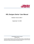
the Symbol Editor, and the Browser. To display this menu, press the right mouse button.
Figure 4-1. The Popup Menu
In the graphic and Symbol editors, the popup menu is displayed when the editor is in “Select”
mode (the Select icon is active), and you click the right mouse button. When the mouse pointer
is positioned on a selected graphic element, the menu includes commands that are pertinent to
the selected element. If more than one element is selected, the menu includes only those
commands that are pertinent to all these elements. When the mouse pointer is positioned on
empty space, the menu includes commands that are pertinent to the unit as a whole.
In the Browser, a popup menu that displays the appropriate commands is always available.
Manipulating Windows
While several Visual Elite windows can be open simultaneously, at any given time only one
window is active.
•
•
On Linux stations, the active window is distinguished by its highlighted border.
In Windows, the active window is distinguished by its blue banner.
The following sections discuss:
•
•
82
Bringing a Window to the Front
Adjusting Magnification
Visual Elite User’s Manual, v4.5
November 2013
The Visual Elite Workplace
Manipulating Windows
•
•
•
•
•
•
•
Using the Panorama View
Scrolling and Panning
Redrawing the Active Window
Making the Grid Visible
Minimizing and Restoring Windows
Reducing the Number of Windows Displayed
Closing Windows
Bringing a Window to the Front
If any part of a Visual Elite window is visible, to bring that window to the front and make it
active, click in the visible part of the window.
On Linux stations, place your pointer anywhere in any Visual Elite window and use the
following function keys to control the Visual Elite windows:
•
•
F4 — brings the main or Simulation Control window to the front.
F8 — brings to the front any currently hidden dialog box that, because it is open, is
preventing other work.
Adjusting Magnification
To display by default, the entire contents of the first page of a graphical unit at the largest
possible size when the unit window is opened, choose Tools > Options Manager> Editors >
Global Settings > General and select the Open in Full Zoom Mode option.
To magnify or reduce your graphics, or revert to the default magnification, use the Zoom
command.
The following sections describe:
•
•
•
•
Zooming In
Zooming Out
Default and Optimal Magnification
Shortcut Key Zooming
Zooming In
You can zoom-in on a particular area or point in a design.
Visual Elite User’s Manual, v4.5
November 2013
83
The Visual Elite Workplace
Manipulating Windows
•
To zoom-in on a particular area of a design (enlarging your graphics):
Choose View > Zoom or the Zoom icon (
)
or
Click and drag from the bottom corner to the diagonally opposite top corner of the
area you need to enlarge. The area you defined is magnified to the largest size that
fits entirely into your window (see Figure 4-2).
Figure 4-2. Enlarging Graphics
•
To zoom-in on a particular point in a design:
Click the Zoom In icon (
)
or
Click the point of interest.
The default zoom-in factor is defined in the Tools > Options Manager > Editors > Global
Settings > General pane. To set the default factor, enter a value for the “Zoom factor” option.
Note
Clicking the Zoom In (or Zoom Out) icon places the editing window in zoom mode.
When you use either of the second methods of zooming, the current value of the Enable multizoom option (also located in the Global Settings > General pane) determines the resulting
behavior:
84
•
If the option is selected, following a zoom operation you remain in the zoom mode and
are able to perform another zoom operation.
•
If the option is not selected, a single zoom in is executed. Following this single zoom,
the select mode is re-entered.
Visual Elite User’s Manual, v4.5
November 2013
The Visual Elite Workplace
Manipulating Windows
Zooming In With the Mouse Wheel
If you are running Visual Elite on any of the supported platforms, to zoom-in in the graphical
editor, press Ctrl and rotate the mouse wheel forwards. If you are running Visual Elite on
Windows, this works for the textual editor as well.
Note
To revert the zoom direction, you need to set the environment variable
VISUAL_WHEEL_ZOOM_DIRECTION to 1.
Zooming Out
You can zoom-out a particular area or from a particular point in a design.
•
To zoom-out (shrinking your graphics):
Choose View > Zoom or click the Zoom icon (
)
or
Click and drag from the top corner to the diagonally opposite bottom corner of the
area into which you need to shrink your currently visible graphics. Your graphics
shrink to fit the area you defined, and the rest of your window is filled by any
adjoining portions of the diagram (see Figure 4-3).
Figure 4-3. Shrinking Graphics
•
To zoom-out from a particular point in the design:
Click the Zoom Out icon (
)
or
Click the point.
The default zoom-out factor is defined in the Tools > Options Manager > Editors > Global
Settings > General pane. To set the default factor, enter a value for the “Zoom factor” option.
Visual Elite User’s Manual, v4.5
November 2013
85
The Visual Elite Workplace
Manipulating Windows
Note
Clicking the Zoom Out (or Zoom In) icon places the editing window in zoom mode.
When you use either or the second methods of zooming, the current value of the Enable multizoom option (also located in the Global Settings > General pane) determines the resulting
behavior:
•
If the option is selected, following a zoom-out operation you remain in the zoom mode
and are able to perform another zoom operation.
•
If the option is not selected, a single zoom-out is executed. Following the single zoom,
the select mode is re-entered.
Zooming Out With the Mouse Wheel
If you are running Visual Elite on any of the supported platforms, to zoom-out in the graphical
editor, press Ctrl and rotate the mouse wheel backwards. If you are running Visual Elite on
Windows, this works for the textual editor as well.
Note
To revert the zoom direction, you need to set the environment variable
VISUAL_WHEEL_ZOOM_DIRECTION to 1.
Default and Optimal Magnification
To revert to the default magnification:
•
Choose View > Zoom or click the Zoom icon (
).
or
•
Click anywhere in your diagram.
To see your whole diagram at the largest size that fits entirely in your window, choose View >
Fit to Window, or click the Fit to Window icon (
)
Shortcut Key Zooming
The zoom-in and zoom-out operations in the graphic editors are attached to the default shortcut
keys indicated in Table 4-2.
Table 4-2. Zoom Shortcut Keys
86
Operation
Default Zoom Factor
Default Assignment
Zoom In
x2
F10
Zoom Out
x0.5
Shift+F10
Visual Elite User’s Manual, v4.5
November 2013
The Visual Elite Workplace
Manipulating Windows
The specified default zoom-in factor for the shortcut keys can be modified using the VEL
(Visual Elite Extension Language) zoom-in-factor-request utility. To change the zoom-in factor
interactively:
1. Choose Tools > Scheme.
2. In the Scheme expression window of the Invoke Scheme dialog box, enter the
expression “(zoom-in-factor-request)”.
3. Click Eval.
4. In the User Text dialog box, type the required zoom-in factor and click OK.
To modify the zoom-out factor, use the VEL zoom-out-factor-request utility.
For information on how to change the shortcut key assignments, see the Visual Elite Extension
Language manual.
Note
When using the shortcut keys to zoom-in or -out, click once in the editor window to
define the zoom point.
Using the Panorama View
In the graphical editors, you can display in a secondary window that provides a panoramic view
of the entire current page of the unit. To access the Panorama window choose View >
Panorama. Within the Panorama window, a red frame indicates that portion of the page
currently displayed in the main editor window. To pan to different portions of the design page in
the main window, click and drag the red frame. To increase or decrease the size of the
Panorama window, right-click and choose the Scale Up or Scale Down menu item.
Scrolling and Panning
The following sections describe:
•
•
Scrolling in the Editors
Auto-Scrolling and Auto-Panning in Graphical Editors
Scrolling in the Editors
To scroll in the graphical or textual editors, use the horizontal and vertical scrollbars located at
the bottom and right side of the window.
Visual Elite User’s Manual, v4.5
November 2013
87
The Visual Elite Workplace
Manipulating Windows
If your mouse is equipped with a mouse wheel, you can scroll as indicated in Table 4-3.
Table 4-3. Scrolling
Operation
Hold Key
Wheel Rotation
Scroll up
--Scroll down
Forward
Backwards
Scroll left
Scroll right
Forward
Backwards
Shift
Remarks
Graphical editors only
Auto-Scrolling and Auto-Panning in Graphical Editors
When you draw a new graphic element, or drag an existing graphic element beyond the confines
of the window frame, the editing window automatically scrolls in the direction of the drawn or
dragged element.
To enable automatic paning when the mouse pointer is brought to an edge of a window, choose
Tools > Options Manager > Editors > Global Settings > General and select the Perform
auto-panning option. For example, if you enable this option and bring the pointer to the righthand edge, the window pans (scrolls) to the right.
Redrawing the Active Window
To redraw the graphics of the active editor window, use any of these methods:
•
•
•
Hit the F2 key.
Choose View > Refresh on Linux or Window > Refresh on Windows.
(On Linux) Click the middle mouse button.
Making the Grid Visible
The Visual Elite graphic editors guarantee that your elements are positioned on a certain grid.
To make the grid visible, choose View > Show Grid in your editor window menu. (Show Grid
is a toggle that can be used to make the grid visible or invisible as needed.)
As a shortcut, you can press F6 to alternately display and hide the grid.
Minimizing and Restoring Windows
In addition to the usual methods for minimizing individual windows, you can use the F7
function key, when your pointer is in any open Visual Elite window, to minimize all editor
windows and Waveform windows (except the main window).
88
Visual Elite User’s Manual, v4.5
November 2013
The Visual Elite Workplace
Browser Controls
In addition to the usual methods for restoring individual minimized windows, you can use
Shift+F7, when your pointer is in any open Visual Elite window, to restore all minimized editor
windows and Waveform windows.
On Windows, you can also use the Window > Iconize All and Window > Deiconize All menu
item.
Reducing the Number of Windows Displayed
To reduce the number of windows the Visual Elite tool opens concurrently on your screen,
choose Tools > Options Manager > Editors > Global Settings > General and enable the
Reduce number of windows option.
When this option is enabled, the Visual Elite tool limits the number of windows so that any
additional window that you open replaces an open window of the same type.
Windows are divided into the following types:
•
•
•
•
block diagram, state diagram, flowchart, or symbol editor windows
truth table windows
textual editor windows
generated code windows
Closing Windows
To close a specific window, choose File > Close or click the Close icon (
.)
To close all open windows, choose Window > Close All in the main or Simulation Control
window.
Browser Controls
The VisualElite browser controls enable you to efficiently manage your design. The following
sections describe how to use the various Browser controls for:
•
•
•
•
•
•
Opening the Browser Window
Setting Browser Display Defaults
Displaying Levels of Detail
Selecting a Unit or Object for Processing or Printing
Performing Data Management Operations
Finding Units and Instances
Visual Elite User’s Manual, v4.5
November 2013
89
The Visual Elite Workplace
Browser Controls
•
•
Defining Access Rights to Units and Libraries
Opening Units and Side Objects
For information about viewing library contents and design hierarchies in the Browser, see “The
Design Environment” on page 125.
Opening the Browser Window
To display the Browser, choose Tools > Browse in the main menu bar. Depending on the
setting currently active, either a single-paned or double-paned adjustable window displays on
your screen. The window features an icon toolbar.
At any time, you can invoke any number of Browser windows, thereby displaying different
portions or views of your environment simultaneously.
Setting Browser Display Defaults
You can choose among different default Browser views of design hierarchies and versioncontrolled projects. The default Browser views are set in the Tools > Options Manager >
Browser > General pane. Changing settings in the Browser General pane of the Options
Manager dialog box does not affect currently opened Browser windows. Only subsequently
opened Browser windows are affected.
The view options include:
•
•
•
Project View
Design Browser View
Browser View
Project View
Click Integrated Project View to display all version-controlled projects in the Browser
window. Click Generic Project View to display projects in a separate Project Manager
window.
Design Browser View
When you click Design Centered Browser View, the Browser displays all available libraries in
your Visual Elite environment. To reveal the design units stored in a library, double-click the
library icon. Selecting a hierarchical unit and clicking the Expand All icon displays only the
design hierarchy beneath that unit.
Click Explorer Like Browser View to revert the Browser to a Windows Explorer type browser
in which you can view the contents of multiple libraries concurrently.
90
Visual Elite User’s Manual, v4.5
November 2013
The Visual Elite Workplace
Browser Controls
Browser View
Click either One Pane or Two Panes display mode.
To toggle between the One Pane and Two Pane views in an already opened Browser window,
click the View Mode icon in the Browser toolbar (see Figure 4-4).
Figure 4-4. Browser View Icon
Displaying Levels of Detail
To control the amount of detail displayed for each design unit in the Browser, use the Tools >
Options > Browser > Display pane. To determine the colors of the different items of
information, use the Tools > Options > Browser > Colors pane.
To override these settings for a particular Browser window, click the Browser Options icon:
(
) and use the Browser Options dialog box.
Selecting a Unit or Object for Processing or Printing
By selecting a unit or stimulus object in the Browser and then choosing the appropriate
command in the Tools menu or clicking the appropriate icon, you can perform the following
operations:
•
•
•
Validate or compile a design unit or stimulus object.
Simulate a design unit.
Generate output code for a design unit or stimulus object.
Selecting the icon in the Browser and choosing File > Print causes the selected unit or object to
be printed.
You can select multiple individual units for validation, compilation, or printing in a number of
ways:
•
•
Press Ctrl and click the icon of each unit to be selected.
•
To select all the units in a Browser window, position the mouse pointer over empty
space in the window, right-click and choose Select All.
To select a range of units, press Shift and click the top and bottom unit in the required
range.
Visual Elite User’s Manual, v4.5
November 2013
91
The Visual Elite Workplace
Browser Controls
•
To select a particular unit and all objects for the unit, expand the Browser to display the
objects to be selected, click the unit icon, right-click and choose Select All.
When you choose Tools > Validate, Compile Unit, or Compile Tree or right-click and choose
Compile, all selected units are processed sequentially.
When you select multiple units or side objects in the Browser to print to individual files, the
Print dialog box Template field displays the library name followed by the literal string objectname. During the creation of the print files, each file is assigned a unique name in the
destination directory, which reflects the name of the unit or object, and the extension
appropriate for the type of print file that was generated.
Performing Data Management Operations
From within the Browser, you can perform the following data management operations:
Table 4-4. Data Management Operations
Operation
Applies to...
Copy
libraries, units, or any side object (except a page)
Rename
libraries, units, or any side object (except a page)
Delete
libraries, units, pages, or any other side object
To perform any of these operations using menu commands:
1. In the Browser window, select the library, unit, or object icon.
2. In the Browser File or Edit menu, or in the Browser popup menu (see “The Popup
Menu” on page 82), choose the appropriate command.
To move units and side objects (with the exception of pages) between libraries, and side objects
between units, use the Browser Cut and Paste commands or drag-and-drop the selected icons.
To copy selected units or objects, press Ctrl and drag-and-drop the selected icons.
To select multiple units and/or objects on which to perform any of these operations, press Ctrl
and click to select their icons one by one, or press Shift and click to define a range of icons.
Finding Units and Instances
The Browser provides two commands (Find and Find Next) that can be used to locate a
particular library, library unit, instance, or side object.
92
Visual Elite User’s Manual, v4.5
November 2013
The Visual Elite Workplace
Browser Controls
A standard search includes only what you can currently see in your Browser window and what
scrolling would show you. (It doesn’t include, for example, the portion of a design tree hidden
by the Collapse All command.)
The search only moves downward in the Browser view. If you have selected a unit, and that unit
is not scrolled too high or low for you to see, the search starts from that unit. Otherwise, the
search starts from the highest unit that is visible in the Browser view.
To perform a search:
1. Choose Edit > Find, select Find in the popup menu, or click the Find icon (
).
A Find command bar opens below the Browser icon bar.
2. In the Find command bar, enter the specifications of the item you need to search for in
the list and text areas.
You can search for a particular library, unit, instance, or side object. The instance name
is the name of the design element or unit that instantiates the library unit and is
displayed in rounded parentheses in the Browser full qualifier. Searching for an instance
name displays the corresponding unit even if, by clearing the full qualifier, you have left
the instance name invisible.
You can use the following wildcards: “?” to mean “any one character” and “*” to mean
“any one or more characters, or none.”
The first unit that matches your specifications is highlighted in the Browser window. If no
match is made, an appropriate message displays. Remember that the search works down the
window only, not necessarily starting at the top.
To search again according to the same specifications, choose Edit > Find Next, use the dropdown menu on the Find icon and click the Find Next icon (
), or click Next on the Find
command bar.
To perform an advanced search of the entire Visual Elite database using more detailed criteria,
click More. The Find dialog box enables you to search for libraries, units, instances, and side
objects by modification date, version number, user checked-out to, type, and compilation status.
Defining Access Rights to Units and Libraries
The Visual Elite tool provides a convenient user-interface for changing the permission to access
and change both units and libraries (see “The Design Environment” on page 125). This interface
reflects the distinctions made by the operating system under which you run Visual Elite:
•
Under Windows, the Visual Elite tool supports the DOS mode of permission, and
therefore defines a unit or library as universally read/writable, read-only, or entirely
inaccessible.
Visual Elite User’s Manual, v4.5
November 2013
93
The Visual Elite Workplace
Browser Controls
•
Under Linux, the Visual Elite tool uses the Linux differentiation of owner, group, and all
other users. For each of these types of users, a unit or library can be read/writable, readonly, or entirely inaccessible.
By default, when a new library is created, read/write permission is granted only to the owner of
the library. All other users get read-only permission for the units stored in that library. If,
however, you change the permission of a library, all units subsequently created in that library
inherit the permission of the library.
Only the owner (the creator) of a library or unit can change its permission status. To change the
permission of a library or unit:
1. Open the unit for editing, or select the unit or library in the Browser. To select multiple
individual units whose permissions are to be changed, press Ctrl and click on the icon of
each unit, or press Shift and click the top and bottom unit in a range.
2. In the editor window or Browser, choose File > Permission.
3. In the Permission dialog box, define the new permission for the unit or library in
question.
Note
In the Permission dialog box displayed for Visual Elite under Windows, the owner of the
unit or library is not displayed. However, as in Linux, a non-owner is unable to change
the settings in this dialog box.
The Visual Elite tool distinguishes between two kinds of read-only status.
•
Units stored in standard libraries supplied with Visual Elite are totally read-only
protected. They can participate in simulation, but they cannot be modified or compiled.
Such units can not be the top of a design hierarchy.
•
Units stored in read/write libraries, but which currently have read-only status (for
example, a unit that is fetched using the Visual Elite version control). In addition to
being simulatable, such a unit can constitute the top of a design hierarchy and can also
be compiled. However, such a unit cannot be modified.
Opening Units and Side Objects
There are two ways to open units and side objects in Visual Elite.
•
•
Double-click the unit or object icon in the Browser.
Choose File > Open.
When you choose the second method, the Open dialog box is displayed. The Units column of
the dialog box lists units of all kinds and subdesign units. The Objects column lists side objects
of the selected design unit. Side objects include breakpoint sets, waveforms, stimulus objects,
94
Visual Elite User’s Manual, v4.5
November 2013
The Visual Elite Workplace
Printing
HDL output, and more. The Units list refers only to the currently selected library and the
Objects list refers only to the currently selected unit.
To specify what to open, click in the Open dialog box lists or type a pathname in the text box. In
a pathname, the library is separated from the unit (if any) by a colon, and each lower-level unit
or object (if any) is preceded by a period. You can create a new unit or object by typing a
pathname that doesn’t yet exist.
To include or exclude a particular type of unit in the Open dialog box list of units, choose Unit
Filter and select the appropriate Design Unit Type in the displayed Unit Filter dialog box.
To include or exclude a particular type of side object in the Open dialog box list of objects,
choose Object Filter and select the appropriate Object Type in the displayed dialog box.
Printing
As you work in Visual Elite, you can print all or part of your graphical and textual units, and the
results of simulation and code generation. This section describes the printing of graphical units,
while instructions related to the printing of results are covered in the appropriate sections of this
User’s Manual.
The following sections describe:
•
•
Printing a Single Diagram
Printing a Design Hierarchy
Printing a Single Diagram
To print a single diagram:
1. Choose File > Printer Setup and adjust your printer setup in the displayed dialog box if
required.
2. Make the diagram window active, or select its icon in the Browser.
3. Choose File > Print or click the Print icon (
) and use the Print dialog box.
4. To print a template together with the diagram select the With Template option.
The template is either the default system template or the template in which you can
define per unit type and page size. (For details on the latter, see “Creating Templates for
Your Designs” on page 203.)
Three read-only text boxes appear at the bottom of the Print dialog box:
•
the leftmost details the name of the unit to be printed
Visual Elite User’s Manual, v4.5
November 2013
95
The Visual Elite Workplace
Printing
•
the middle one displays a time stamp that records the time at which you issued the
Print command
•
the rightmost is reserved for the page number when multiple pages are printed
The other rectangular boxes can be used to type remarks that are to be incorporated in
the printout if you are using the system default template for the current page. Remarks
are not printed if you have assigned a user-defined template to this page.
To select multiple individual units for printing, press Ctrl and click the icon of each unit. To
select a range of units, press Shift and click the top and bottom unit in the required range.
Printing a Design Hierarchy
The inclusive printing command, called Print Tree, issues a Print command for the currently
selected design unit and for every unit and subdesign unit in the hierarchy beneath it. However,
note the following points:
•
The printout from Print Tree might contain many pages, but it is a single file, and its
pages are numbered in a single continuous sequence.
•
Print Tree does not print packages, package bodies, Verilog “includes”, or side objects
other than pages.
•
To print a design hierarchy, select a design unit, rather than a subdesign unit. If you
select a subdesign unit, only that one subdesign unit is printed. (If a design unit is
selected, all the subdesign units in its hierarchy are printed.)
•
If you select a page for Print Tree, the printout also includes the other pages of the same
unit.
•
If a library unit or subdesign unit is instantiated more than once in your tree, it is printed
only once. Any skipping of duplicate instantiations is reported in the Messages window.
•
If some HDL text unit needs fresh compilation, the Print Tree operation does not
proceed past that pair. (For other units, compilation status is not a consideration.)
To print a design hierarchy (printing a unit and all the other units it instantiates):
1. Click File > Printer Setup and adjust your printer setup in the displayed dialog box if
required.
2. Make the unit active in an editor window, or select its icon in the Browser.
3. Choose File > Print Tree. The Print Tree dialog box opens.
4. Make your selections in the Print Tree dialog box, then click OK.
Each page of the printout shows the name of its own unit, even though the page numbering is a
single sequence covering the whole Print Tree output file.
96
Visual Elite User’s Manual, v4.5
November 2013
The Visual Elite Workplace
Saving and Reloading Your Working Environment
To select multiple hierarchical units on which to implement Print Tree, press Ctrl and click the
icon of each such unit. To select a range of units, press Shift and click the top and bottom unit in
the required range.
Saving and Reloading Your Working
Environment
The “working environment” that you create as you work in Visual Elite, refers to all sorts of
general settings and preferences that you specify by means of menus and dialog boxes. These
settings can either be saved or discarded, depending on your requirements.
The working environment is saved in the initialization file currently in use — which, by default,
is the initialization file that was loaded during invocation. (For a description of the initialization
file, see “Setup and Invocation” on page 47.)
To save your working environment:
1. In the main menu bar, choose File > Save Environment.
2. In the Save Environment dialog box, specify the Visual Elite initialization (.ini) file in
which you need to store your settings.
The Save Environment command also records which Visual Elite windows are open and how
they are sized and positioned. If you invoke Visual Elite with the -env option, the system
restores the window configuration that was on your screen when you last used the Save
Environment command (see “Setup and Invocation” on page 47).
To switch to a different working environment (that is, load a different initialization file) anytime
after invocation:
1. choose File > Load Environment.
2. In the Load Environment dialog box, enter the name of the initialization file you need to
load. (The dialog box assumes that your initialization file has the .ini filename
extension.)
Customizing Visual Elite
The Visual Elite tool provides a sophisticated, scheme-based extension language called VEL
(Visual Elite Extension Language). By writing scripts in VEL, you can extend and customize
Visual Elite functionality, and automate large amounts of otherwise repetitive work.
VEL scripts can be used in two modes of work:
•
Batch — Batch-mode scripts are written to perform complete operations in an off-line
mode. Such operations deal with overall functionality.
Visual Elite User’s Manual, v4.5
November 2013
97
The Visual Elite Workplace
Shortcut and Function Keys
•
Interactive — Interactive-mode scripts are written to automatically perform certain
preliminary operations prior to working interactively with Visual Elite.
For complete details on how to write and run VEL scripts, see the Visual Elite Extension
Language manual.
You can also prepare and run scripts for Visual Elite written in either Perl or Tcl. For more
information, see “Using Perl and Tcl Scripts with Visual Elite” on page 549.
The Visual Elite tool enables you to add to menus the features that you use regularly, such as
commands and VEL scripts, and remove from menus the features that you rarely use. (For more
information about VEL scripts, see the Visual Elite Extension Language manual.)
You can customize menus and key assignments by creating those handiest for you. You can
preserve the original Visual Elite settings and create separate template files for customized
settings. To customize menus and key assignments, preserve the original Visual Elite settings,
and create separate customized settings template files:
1. In the Tools > Options Manager > Customization pane “User-defined menu
directory” option, enter the name of the directory in which to store your customized
settings.
2. In the main menu bar, choose Tools > Customize, and use the Customize Menu dialog
box.
Note
Menu configuration changes made using the Customize menu item are not applied
immediately; to see the changes, you must re-invoke Visual Elite.
To revert to the Visual Elite default settings, click Default in the Tools > Customize dialog
box. (See note above.)
Shortcut and Function Keys
Table 4-5 summarizes the default settings for shortcut key combinations used in Visual Elite.
You can reconfigure these key combinations using the Visual Elite Extension Language (VEL).
For details, see the Visual Elite Extension Language manual.
Table 4-5. Shortcut and Function Keys
98
Key Combination Command
Key Combination
Command
Control+O
Open (unit/object)
Control+X
Cut
Control+S
Save (library
/unit/object)
Control+C
Copy (in design)
Shift+Control+S
Save All
Control+V
Paste
Visual Elite User’s Manual, v4.5
November 2013
The Visual Elite Workplace
Online Help and Tool Tips
Table 4-5. Shortcut and Function Keys (cont.)
Key Combination Command
Key Combination
Command
Shift+Control+C
Copy (library
/unit/object)
Control+Z
Undo
Shift+Control+M
Move (library
/unit/object)
Delete
Delete
Shift+Control+R
Rename (library
/unit/object)
Control+M
Comment Line
(in the text editors), or
Toggle Pin (Connector)
Direction (in the Block
Diagram Editor)
Control+R
Refresh Libraries
Control+U
Uncomment Line
Control+P
Print
Control+Y
Invoke
Symbol Editor
Note
If the Num Lock button in the keyboard is pressed (Num Lock is active), the keyboard
shortcuts will not work at all.
Table 4-6 summarizes the use of function keys in Visual Elite. Unlike the shortcut key
combinations listed in Table 4-5, function keys cannot be reconfigured.
Table 4-6. Function Keys
Function Key
Command
Function Key
Command
F1
Online Help
F7
Minimize All windows
F2
Refresh Screen
Shift+F7
Restore All windows
F3
Display Element Attributes
dialog box
F8 (Linux only)
Bring forward open dialog
box/window
F4 (Linux only) Bring forward Main or
F10
Simulation Control window
Zoom In
F6
Zoom Out
Toggle Grid
Shift+F10
In addition, numerous shortcut key operations are available with the Visual Elite internal text
editor. For details, see “Keyboard Commands (1)” on page 270.t.
Online Help and Tool Tips
The Visual Elite tool includes online Help to assist you as you work.
•
To display the top of the Help tree, choose Help > Help Topics.
Visual Elite User’s Manual, v4.5
November 2013
99
The Visual Elite Workplace
Online Help and Tool Tips
•
•
To display Help specific to any dialog box, click Help in the dialog box.
•
To display Help specific to a window (such as an editing window), press F1 while your
mouse pointer is positioned in that window.
To display Help specific to a menu command, highlight the command using your mouse
and press F1.
Tool tips display the names of the Visual Elite icons. To see the name of any command icon,
rest your mouse pointer on it for a moment. Similarly, a tool tip is displayed whenever the
mouse pointer rests on a graphic element within an editing window: the element type and name
are displayed.
100
Visual Elite User’s Manual, v4.5
November 2013
Chapter 5
Common Editor Options
This section describes operations that are common to the Visual Elite editors: the Block
Diagram, State Diagram, Flowchart, and Truth Table graphical editors, as well as, where
relevant, the Visual Elite textual editors.
The following sections describe:
•
•
•
•
•
•
•
•
•
Creating a New Unit
Graphic Elements
Text in Graphic Units
Undoing and Redoing Steps of Work
Moving Up the Design Hierarchy
Displaying Global Data
Pages
Validating a Unit
Saving Units and Objects
Creating a New Unit
To create a new unit, using the main or Browser menu, choose File > New, and specify the type
of unit that you need to create; for example, Block Diagram, State Diagram, or Flowchart.
The appropriate editor window opens, and you can begin creating the new unit.
The Visual Elite tool enables you to depict units in any of three languages: VHDL, Verilog, or
SystemC. To override the global new unit language and create a unit in a different language,
choose File > New > Language > Unit Type in the Editor.
For VHDL, the Visual Elite tool enables you to create units that conform to either the VHDL 87
or VHDL 2008 standard. To set the default standard of new units, choose Tools > Options
Manager > Compiler Settings > General and set the “Compile as” value in the VHDL tab
sheet of the General window. If you select VHDL 87, VHDL 87 units are created. VHDL 2008
units are created when you select VHDL 2008. The “Compile as” option also determine the way
a VHDL unit is compiled (see “Specifying VHDL Type” on page 611).
Visual Elite User’s Manual, v4.5
November 2013
101
Common Editor Options
Graphic Elements
Graphic Elements
This following sections describe issues related to working with graphic elements in the Block
Diagram, State Diagram, and Flowchart editors:
•
•
•
•
•
•
•
•
•
•
•
•
•
•
Placing Graphic Elements in a Diagram
Selecting Elements in a Diagram
Deselecting Elements in a Diagram
Defining Attributes for Graphic Elements
Defining Default Names for Graphic Elements
Specifying Graphic Element Colors
Resizing Graphic Elements
Moving Graphic Elements
Copying Graphic Elements
Duplicating Graphic Elements
Rotating Graphic Elements
Deleting an Element
Using Free Graphics in Graphical Editors
Inserting External Bitmaps in Graphical Units
Placing Graphic Elements in a Diagram
In the Block Diagram, State Diagram, and Flowchart editors, several of the icons are used to
place graphic elements into the diagram. For example:
Table 5-1. Graphic Element Icons
Create a block (in the Block Diagram Editor)
Create a state (in the State Diagram Editor)
To place a required element:
1. Click the appropriate icon. The outer shading of the icon changes, indicating that it is
selected.
2. Click in the window where you need the element placed.
102
Visual Elite User’s Manual, v4.5
November 2013
Common Editor Options
Graphic Elements
Depending on what the element is, you might need to click twice (for example, for a
block in the Block Editor) or even three times (for a transition in the State Diagram
Editor). More detailed instructions are given where appropriate in the following
chapters.
As a rule, the element is automatically assigned a default name.
For example, default names for blocks start with B (B0,
B1, and so forth) and default names for signals start with
S (S0, S1, and so forth).
If required, you can define your own preferred default names; for details, see “Defining
Default Names for Graphic Elements” on page 106. In Visual Elite, you can assign a
graphic element any name that is legal in VHDL or Verilog, depending on the language
in which the unit is depicted. In SystemC block diagrams, you can assign legal C/C++
names.
3. To create more elements of the same type, click where you need them to be placed.
You do not need to click the icon again since, once selected, each of the icons remains
selected until you select a different icon or perform a right-click.
Right-click to cancel the drawing of a graphical element after you have started.
Selecting Elements in a Diagram
In the Block Diagram, State Diagram, and Flowchart editors, you can select elements either
individually, or together with other elements.
Selecting Individual Elements
To select individual elements (and any associated text):
1. Click the Select icon (
) or right-click anywhere in the diagram.
2. Click on an element to select it and its accompanying text (if any).
The element, and any accompanying text, changes color to indicate it is selected.
When you select another element, the previously selected element is deselected.
Selecting More Than One Element One at a Time
To select more than one individual element, one at a time:
1. Click the Select icon (
) or right-click anywhere in the diagram.
2. Press Shift and sequentially click on each of the elements to select.
Visual Elite User’s Manual, v4.5
November 2013
103
Common Editor Options
Graphic Elements
Selecting a Line
To select a line up to the nearest intersection (node), click the Select icon (
) then click the
segment of line that you need to select. To select an entire line up to all endpoints, double-click
anywhere on the line.
Selecting Multiple Elements in an Area
To select all the elements contained in a rectangular area, as well as their associated text (such
as their names), click the Select icon (
). Locate a corner of the area where no element is
present and click-and-drag a rectangle around all the elements you need to select. The elements
change color, indicating they have been selected.
Selecting Elements Based on Predefined Criteria
To select elements based upon predefined criteria:
1. In the graphical editor, click Edit > Query Select or right-click in an empty area of the
diagram and choose Query Select from the popup menu.
2. In the Query Select dialog box, click the Drawing option to select elements found
throughout the entire current page, or click the Select List option to select a subset of
already selected elements.
3. Define the elements to be selected using the Select by Name and Select by Type options
as required.
For example, if you need to select all the blocks whose names begin with the letter “M”
in a block diagram, click the Blocks option and enter the string “M*” in the Select by
Name text box.
4. Specify a signal or port name to select the items connected to the signal or port. Regular
expressions are allowed.
a. Check the Tree option to select all items connected to the signal or port recursively
in the design.
b. Check the Include Pages option all items connected to the signal or port on all pages
contained in the current unit.
Using the various available options, you can specify as many criteria as you require. Once the
elements you specify are selected, you can manipulate them; for example, you can change the
color of the selected elements (see “Specifying Graphic Element Colors”). This type of
selection is particularly useful in conjunction with defining attributes for multiple graphical
elements.
104
Visual Elite User’s Manual, v4.5
November 2013
Common Editor Options
Graphic Elements
Selecting All Elements in a Diagram
To select all the elements in your diagram, click the Select All icon (
choose Select All.
) or right-click and
Deselecting Elements in a Diagram
The following sections describe how to deselect individual and all elements in a selection
group.
Deselecting Individual Selected Elements
To deselect one particular element in a selection group, click the Select icon (
Shift and click the element.
) then press
Deselecting All Selected Elements
To deselect all elements you have previously selected, perform one of the following actions
without pressing Shift:
•
•
Select a new element.
Click in an empty area of the diagram.
Defining Attributes for Graphic Elements
All of the graphic elements used in the various editors have definable attributes; for example,
the conditions governing a state transition or the contents of a block. The following sections
describe how to define the attributes of individual or multiple elements:
Defining Attributes of Individual Elements
To define or modify these attributes, use the appropriate dialog box.
1. Click the Select icon (
).
2. Click the element.
3. Click the Attributes icon (
).
Alternatively, you can press F3, click Attributes > Element, or right-click and choose
Attributes in the popup menu.
4. In the Attributes dialog box, define the required attributes. (For details, see the
individual editor chapters.)
5. After defining the required attributes, click Apply (the dialog box remains open) or OK
(the dialog box closes) to save the attributes. Click Cancel to close the dialog box
without saving the changed attributes.
Visual Elite User’s Manual, v4.5
November 2013
105
Common Editor Options
Graphic Elements
Defining Attributes of Multiple Elements
To “page through” and define the attributes of multiple elements in a diagram:
1. Select all the elements whose attributes you need to change. (See “Selecting Elements in
a Diagram” on page 103.)
2. Choose Attributes > Element.
The Attributes dialog box for the initial element in the selection group opens.
3. Define the required attributes using the Attributes dialog box.
4. Click Apply.
The defined attributes for the initial element in the selection group are saved and the
Attributes dialog box for another selected element is automatically opened.
5. Continue to sequentially modify the attributes for the various elements.
6. When you have made the required modifications to the last selected element, click OK.
The dialog box closes.
Defining Default Names for Graphic Elements
To define a default name for any or all of the graphic elements of a given type:
1. Choose Tools > Options Manager > Editors > Graphic Editor > Default Names,
where Graphic Editor is: Block Diagram, State Diagram, or Flowchart.
2. In the Editors pane of the Options Manager dialog box, enter the prefix and optional
suffix of the default name for each listed element.
A running integer is appended to the prefix when you create the element.
Prefixes and suffixes can be defined for the following graphical elements:
•
•
•
Block diagrams — blocks, components, signals or bundles, and taps
State diagrams — states, transitions, and connectors
Flowcharts — start boxes, action boxes, condition boxes, wait boxes, loop boxes, end
loop boxes, case boxes, end case boxes, state boxes, and connectors
Specifying Graphic Element Colors
To set default fill and bordering line colors for graphic elements in Block Diagrams, State
Diagrams, and Flowcharts, choose Tools > Options Manager > Editors > Graphic Editor >
Colors; where Graphic Editor is: Block Diagram, State Diagram, or Flowchart.
106
Visual Elite User’s Manual, v4.5
November 2013
Common Editor Options
Graphic Elements
To modify the color of graphic elements locally, select the element(s) then right-click and
choose Colors. In the Set Color dialog box, select the fill and line colors. Color is applied to all
selected items, not just selected items on the current window.
To specify default colors to be displayed when graphic elements are selected with the cursor,
when the Attributes dialog box is open, or during a pause in simulation, choose Tools >
Options Manager > Editors > Global Settings > Colors.
Resizing Graphic Elements
To resize blocks, states, and all other resizeable graphic elements:
1. Select the graphic element.
2. Place your pointer on the edge or corner you need to move inward or outward.
The pointer changes to a crosshair (+).
3. Click-and-drag toward or away from the center of the graphic element.
The edge or corner moves with your pointer, resizing the graphic element.
Note
You can use the same method to convert the default circular shape of a state to an ellipse.
Moving Graphic Elements
After you place graphic elements in an editing window, you can move them as described in the
following sections.
Moving an Individual Graphic Element
To move an individual graphic element:
1. Click the Select icon (
) or right-click anywhere in the diagram.
2. Click-and-drag the element to its new location.
Moving Multiple Graphic Elements
1. Select the elements you need to move.
2. Click-and-drag a selected element to a new location. All selected elements are moved.
Visual Elite User’s Manual, v4.5
November 2013
107
Common Editor Options
Graphic Elements
Copying Graphic Elements
In Block Diagrams, State Diagrams, and Flowcharts, you can copy any graphic element. For the
copies, the original names are used where reasonable (for example, the names of instantiated
units and components in block diagrams). Where it is not reasonable to duplicate the original
name (for example, the name of a state), new default names are automatically assigned. In some
cases, while the original name is retained, the name might require editing (such as local
connector names).
When copying elements, you can use the system clipboard or bypass the clipboard using a
shortcut. (The clipboard, as in many other graphical and text editors, is an off-screen location
from which many duplicates can be made. You copy to the clipboard and paste from the
clipboard.)
To copy graphic elements not only within a unit, but also between units of the same type using
the clipboard:
1. Select the element or elements that you need to copy.
2. Click the Copy icon (
) or choose Edit > Copy.
Alternatively, you can right-click and choose Copy from the popup menu.
3. To copy into another diagram, make that diagram window active.
You cannot copy into a diagram that belongs to another editor. For example, you cannot
copy from a block diagram into a state diagram.
4. Click the Paste icon (
) or choose Edit > Paste. Alternatively, you can right-click and
choose Paste from the popup menu.
The copy retrieved from the clipboard moves with your pointer.
5. Move the copy into position and click to drop it. Or, to delete the copy, right-click or
press Delete on the keyboard.
6. To place another copy of the same element(s), return to step 4.
Your clipboard retains its content until you use the Copy command again or exit Visual
Elite. It is separate from the text-editing clipboard.
To move duplicated elements after dropping them, move them like any other elements (see
“Moving Graphic Elements” on page 107).
Duplicating Graphic Elements
Instead of just copying and pasting a graphic element a number of times, the Array command
provides a quicker way to duplicate a graphic element several times:
1. Select the element.
108
Visual Elite User’s Manual, v4.5
November 2013
Common Editor Options
Graphic Elements
2. Choose Edit > Array or right-click and choose Array from the popup menu.
3. In the Array dialog box, specify any of the following options:
o
Horizontal — the number of elements to be created in a row.
o
Vertical — the number of elements to be created in a column.
o
Diagonal — the number of elements to be created diagonally.
You can enter numeric values for both Horizontal and Vertical, and create a twodimensional array of elements. However, if you enter a value for Diagonal, neither
Horizontal nor Vertical can be specified.
4. Move the pointer to position the elements, and click to drop them.
The elements are spaced evenly from one another.
Rotating Graphic Elements
Depending on the graphical editor that you are using, the elements in Table 5-2 can be rotated.
Table 5-2. Elements That Can Be Rotated
Diagram
Elements
Block Diagram
signal names, components, connectors, connector names,
block names, taps
State Diagram
connectors, connector names, other element names
Flowchart
connectors, connector names, box names
To rotate a graphic element:
1. Select the element to be rotated.
2. In the Edit toolbar, click the Rotate icon (
).
With each click, the element rotates 90 degrees counterclockwise.
In Block Diagrams after you rotate a component, unless disabled, autorouting can be used to
adjust the paths of signals in order to keep them as clear and separate as possible. To disable
autorouting, click Tools > Options Manager > Editors > Global Settings > General and
deselect the “Perform auto-route” option.
Deleting an Element
To delete an element, such as a block or signal in the Block Diagram Editor, use one of the
following methods:
•
Select the element, and click the Delete icon (
Visual Elite User’s Manual, v4.5
November 2013
).
109
Common Editor Options
Graphic Elements
•
Select the element, and choose Delete or Cut in either the Edit or popup menu.
If you use the Cut command, the deleted element is retained in the clipboard.
•
Select the element and press the Delete key.
Using Free Graphics in Graphical Editors
In the Block Diagram, Stage Diagram, and Flowchart editors, you can add free graphics to your
design units. Free graphics do not have a logical significance on the design, but can be used for
documentation purposes. To use any of the free graphics commands:
1. Right-click in an empty area of the design page.
2. Choose one of the following: Line, Circle, Arc, or Rectangle.
3. In the editing window, click and begin drawing the required shape or line. Click again to
conclude the drawing.
4. If required, draw any additional lines or shapes of the same type you might need.
5. Right-click to exit the drawing mode for this shape or line.
You can manipulate free graphics objects as required. Select one or more of the shapes in the
editing window. Right-click and choose Fill, Unfill, Group, or Ungroup.
Inserting External Bitmaps in Graphical Units
In the Block Diagram, State Diagram, and Flowchart editors (as well as in the Symbol and
Template editors), you can insert external bitmap images. Such images do not have a logical
significance in the design, but can be used for aesthetic and/or documentation purposes.
The bitmaps to insert can be stored in one of the following directories, which are listed
according to their order of priority:
•
The directory specified in the Tools > Options Manager > Editors > Global Settings
> General > Bitmap directory option.
•
•
•
The directory referenced by the environment variable VISUAL_EXTERN_BITMAPS.
The default directory that you create at visual_installation_dir/runtime/bitmaps.
A directory named /bitmaps that you create in the directory where the current .ini file is
stored.
To insert a bitmap in a design unit:
1. Right-click in an empty area of the design page.
2. Choose External Bitmap.
110
Visual Elite User’s Manual, v4.5
November 2013
Common Editor Options
Text in Graphic Units
The Bitmaps dialog box lists all the bitmaps stored in the bitmap directories searched by
Visual Elite.
3. Select the name of the bitmap file to be inserted and click OK.
Note
You can also insert a bitmap which is stored in a different directory. Click Import in the
Bitmap dialog box. Browse to the location of the bitmap you need to insert. Click OK in
the Bitmap dialog box. The bitmap is inserted in the unit window and copied to the
designated bitmap directory.
Text in Graphic Units
The following sections describe issues related to the use of text when working in the Visual
Elite editors:
•
•
•
•
•
•
•
•
•
•
Copying All Kinds of Text
Editing Text on Screen
Specifying Font Style for Text
Controlling Visibility of Graphic Element Text
Finding and Replacing Text in Design Units
Adding Free Text to a Diagram
Defining Unit Headers
Entering Japanese Comments
Automatically Aligning Graphics and Text
Editing Textual Units
Copying All Kinds of Text
Anywhere you type text (as free text, textual units, specifications in a dialog box, or values in a
truth table) the same clipboard is shared. Using the shared clipboard, you can copy text from
place to place in Visual Elite: from a truth table into a textual unit, from the action of a state
transition to the action of a flowchart box, or between any two boxes where text is editable. You
can copy as little as a signal name, or up to dozens of lines of code.
One way to copy text is as follows:
1. If it isn’t already, make the text available for editing; for example, if it is free text, or a
state diagram action or condition, open its dialog box.
Visual Elite User’s Manual, v4.5
November 2013
111
Common Editor Options
Text in Graphic Units
2. Drag the cursor to select the text to copy.
3. Press Ctrl+Insert to copy the text to the clipboard.
4. Click where you need to re-use the selected text.
5. Press Shift+Insert to paste the text from the clipboard.
See “Writing Text” on page 263 for a complete set of text-editing commands.
Editing Text on Screen
Much of the text displayed in graphical units can be edited directly in the graphical editor
window, without having to bring up dialog boxes. For example, the names of all graphic
elements, the width of signals, all free text, actions, transition guard conditions, and more.
When you edit such textual items on screen, you change their values in the database.
To edit text on screen:
1. Select the text.
2. Click the text. The selected text now appears in an editable rectangle.
3. Modify the text as required.
To cancel editing if required, press Esc.
4. Click anywhere in the editing window to finalize the editing.
If the edited text is single-lined, you can press Return or Enter to finalize the editing.
Specifying Font Style for Text
To specify a default font to be used for text in graphical and textual units:
1. Choose Tools > Options Manager > Editors > Global Settings > Fonts.
2. In the Editors pane, specify the font to be used for graphical element names, free text,
and in the text editors.
a. In the appropriate field, click the drop-down button.
b. In the Font dialog box, set the font attributes.
Note
In dialog boxes that provide a Font button, you can locally override the default font.
In Block Diagrams, State Diagrams, and Flowcharts, you can modify the font used for any
selected text. Choose Attributes > Font. In the Change Font dialog box, specify the new font
attributes.
112
Visual Elite User’s Manual, v4.5
November 2013
Common Editor Options
Text in Graphic Units
Controlling Visibility of Graphic Element Text
Graphic elements in Block Diagrams, State Diagrams, and Flowcharts are generally
accompanied by text. Using the appropriate Attributes dialog box, you can toggle the text on or
off. The text can be moved independently of the element to which it belongs.
To change the visibility of accompanying text, choose Tools > Options Manager > Editors >
Graphic Editor > Visibility; where Graphic Editor is: Block Diagram, State Diagram, or
Flowchart. Specify which text in a given graphical editor is visible, and which is invisible. To
make the text accompanying a particular type of element visible, select its checkbox. Table 5-3
lists the text elements whose visibility you can control.
Table 5-3. Text Elements with Visibility Control
Block Diagrams
Blocks: Name,
Generic/Parameter
values, Text, Ports
State Diagrams
States: Name, Action
Flowcharts
Start boxes: Name,
Sensitivity List
Action boxes: Name,
Components: Name,
Transitions: Name,
Generic/Parameter values Guard condition, Priority, Action
Action
Signals/Bundles: Name,
Contents
Page Connectors: Name State boxes: Name,
Action
Taps: Name,
Assignments
Other Connectors:
Name
Signal Pins: Name,
Page Reference
Condition boxes: Name,
Condition
Wait boxes: Name,
Statement
Global Connectors:
Name, Priority, Condition
Page Connectors: Name
Case boxes: Name,
Choices, Expression
Loop boxes: Name,
Statement
Using the Tools > Options > Editors > Graphic Editor > Visibility menu item to access a
Visibility dialog box, enables you to set the default visibility for each subsequent unit of the
given element type created.
To change the visibility for each unit locally, choose Attributes > Visibility in the graphic
editor. When you change the visibility locally, the new setting is applied to:
Visual Elite User’s Manual, v4.5
November 2013
113
Common Editor Options
Text in Graphic Units
•
•
any currently selected element
all subsequently created elements for this unit
Finding and Replacing Text in Design Units
You can find all occurrences of a string, either locally or across all pages of an entire unit or
hierarchical design tree.
To find a string in a given unit:
1. Click the Find icon (
), choose Edit > Find, or right-click when no element is
selected and choose Find in the popup menu.
2. In the Find dialog box, specify how to display the search results: interactively or as a
single report. If interactively, click Next or Previous.
o
Interactive:
The Find dialog box closes and the search begins in the specified direction. If the string
is found, its first occurrence is displayed. Each subsequent click on the Find Again icon
(
) displays the next or previous occurrence of the string.
To change the direction of the search, click the Find icon. The Find dialog box reopens
enabling you to select the appropriate directions: Next or Previous.
o
Report:
The Search Results dialog box opens and contains a list of all found occurrences of the
string. Double-click any of the findings listed in this dialog box to highlight the actual
occurrence of the string in the design.
To find and replace a string of text:
1. Choose Edit > Replace or right-click and choose Replace from the popup menu.
The Replace dialog box opens.
2. In the Replace dialog box Replace field, enter the string to be searched for and replaced.
3. In the With field, enter the new string.
4. Specify the mode of the search and replace operation:
114
o
Query — Each consecutive occurrence of the found string is highlighted in the
window or dialog box in which it is located. As each occurrence is displayed,
confirm whether the string should be replaced.
o
All — All occurrences of the found string are replaced at once. Changes made in
closed units are saved automatically.
Visual Elite User’s Manual, v4.5
November 2013
Common Editor Options
Text in Graphic Units
Adding Free Text to a Diagram
Among the elements you can place in Block Diagrams, State Diagrams, and Flowcharts is free
text; text that the Visual Elite tool does not process but simply displays as comments among
your graphics. You can attach free text (including RCS keywords) to an entire unit. Free text
comments can be linked specifically to the following graphical elements:
•
•
•
Block Diagram Editor — blocks and components, signals and bundles, taps
State Diagram Editor — states, transitions, junctions, connectors
Flowchart Editor — start boxes, action boxes, state boxes, decision boxes, wait boxes,
loop and end loop boxes, case and end case boxes, connectors. (You cannot attach a
comment to an end box.)
Besides putting free text into a diagram, you can store text as a side object associated with a
diagram. For details, see “The Visual Elite Workplace” on page 79.
Linking Free Text to an Entire Unit
To create and link free text to an entire unit:
1. Click the Free Text icon (
).
The Free Text dialog box opens.
2. In the Free Text dialog box, type the text to place.
If you need to edit as you type, see “Writing Text” on page 263 for details of the
available keyboard commands. Some of the icons described are also available in the
Free Text dialog box.
3. Select the appropriate “Attach to” option to specify where to include the free text
comments in the code generated for your unit.
For VHDL units, you can attach comments to either entity or architecture declarations.
For Verilog units, you can attach comments to module declarations. If you select
Graphics only, your comments are displayed in the diagram but not in the generated
code.
4. If you have specified Entity, Architecture, or Module in the previous step, select the
appropriate Position option to determine the position of your comments relative to the
appropriate declaration in the generated code.
5. If you need to modify the style, size, and color of fonts used, click Font and use the Font
dialog box.
6. To draw a frame around the free text, select the Frame Visible option.
7. Click OK.
The text attaches itself to your pointer.
Visual Elite User’s Manual, v4.5
November 2013
115
Common Editor Options
Text in Graphic Units
8. Click in the diagram to place the text.
Once created and linked, you can move or copy the element of free text like any other diagram
element. To revise the text, select only the free-text element and click the Free Text icon. Its
dialog box reopens.
Linking Free Text to a Specific Graphic Unit
To link free text to a specific graphic element:
1. Select the element.
2. Click the Free Text icon (
).
3. In the appropriate field of the displayed dialog box (for example, the Comments dialog
box or the Comments tab sheet of the Attributes dialog box), type your text.
Text that you enter in the “Before” field is placed in the generated code, just before the
declaration line that represents the element. Text entered in the “At” or “Same Line”
field is appended to the declaration line. “After” text is placed just after the line.
For more specific information about the location of the free text in the HDL output of
your design, see “Where Free Text Appears in the HDL Code” on page 523.
4. To make your text visible in the diagram, select the Visible option.
5. Click OK.
The positioned text automatically includes the name of the element.
Linking Free Text to a URL
Any free text integrated in Block Diagram, State Diagram, or Flowchart units can be linked to
the URL of your choice. When this hyperlinked text is clicked, the default internet browser on
your system is invoked, and the specified URL is loaded.
To define a hyperlink for free text:
1. Click on the text to select it.
2. Right-click and choose Hyperlink.
3. In the Hyperlink dialog box, enter the URL to be referenced by the hypertext.
4. Click OK.
Defining Unit Headers
In addition to free text, the Visual Elite tool enables you to specify unit headers that can
incorporate RCS keywords for version control purposes. When a unit is checked-in (see
116
Visual Elite User’s Manual, v4.5
November 2013
Common Editor Options
Text in Graphic Units
“Version Control” on page 141), the keywords are evaluated; the values display the next time
the unit is checked-out or fetched.
For example, if you enter the RCS keyword $Header$, after evaluation the following displays in
place of the keyword: full pathname of the RCS file, revision number, date and time, author,
state, who locked the unit.
Defining a Page Header
In principle, each page of a Block Diagram, State Diagram, or Flowchart can be given its own
individual header. To assign an individual header to a page:
1. Choose Attributes > Header.
2. In the Header dialog box, type the header text for the page.
3. Select the Visible option.
4. Click OK.
The header text is attached to your mouse pointer.
5. Position the pointer to place the text and click.
Defining a Default Global Header
You can pre-define a default global header for every textual and graphical unit that you
subsequently create. In textual units, the header text is displayed as comments preceding the
unit code; in graphical units, it is displayed in the Header dialog box.
To define a default global header
1. Choose Tools > Options Manager > Editors > Global Settings > Global Header.
2. In the Editors pane, specify the types of graphical and textual units to which to apply the
default header.
3. In the text window, enter the required contents of the default header.
To integrate the unit header in the output during code generation, choose Tools > Code
Manager > Style > Headers and click the “Unit user-defined header” option. (For details, see
the “Attaching Headers” on page 508.)
Entering Japanese Comments
An environment variable, VISUAL_TEXT_LANG, is provided to indicate to Visual Elite that it
is being run under a Japanese operating system. The Visual Elite tool uses this information in
maintaining its database.
Visual Elite User’s Manual, v4.5
November 2013
117
Common Editor Options
Text in Graphic Units
Set the environment variable as follows:
Linux
setenv VISUAL_TEXT_LANG ja
Windows
set VISUAL_TEXT_LANG=ja
Where “ja” is in lowercase.
Once the environment variable is set, you can choose Tools > Options Manager > Editors >
Global Settings > Fonts and select the jisx0208.1983 option in the Editors pane. The Editors
pane Font sheet enables you to select from a number of available fonts for the language in use.
(For more details about using the Visual Elite environment variables, see “Setup and
Invocation” on page 47.)
Note
As an alternative to using the VISUAL_TEXT_LANG environment variable provided by
Visual Elite, you can use the general environment variable LANG. This variable should
be assigned the value “ja”.
Automatically Aligning Graphics and Text
In a graphical editor, to align graphic elements and text boxes automatically:
1. Select the elements to align.
2. Choose Edit > Align.
3. Use the controls in the Alignment dialog box.
Editing Textual Units
The Visual Elite tool offers you a number of possibilities for editing textual units:
•
•
•
•
XEmacs, the default editor
Mentor Graphics’ DesignPad editor
Visual Elite internal text editor
Any other external editor of your choice that can be invoked from within Visual Elite
For details, see “Writing Text” on page 263.
118
Visual Elite User’s Manual, v4.5
November 2013
Common Editor Options
Undoing and Redoing Steps of Work
Undoing and Redoing Steps of Work
Each of the Visual Elite graphical editors has an Undo and Redo icon.
Using the Undo command cancels recent changes made to graphic elements in a design unit.
For example, you can undo the deletion of a signal in a Block Diagram, or you can undo a
change in the action of a state in a state machine. You cannot undo actions that do not relate to
specific graphic elements. For example, using the Undo icon you cannot undo a change to the
list of generics defined for a VHDL unit.
Saving your unit does not affect your ability to undo work, but closing your window does.
When you open a window, you cannot undo changes that were made before you last closed it.
To undo the latest action or actions affecting your graphic elements, click the Undo icon (
as many times as necessary.
)
To redo an action or actions that you undid, immediately after the Undo command, click the
Redo icon (
) as many times as necessary. The Redo command does not work on any changes
you make to graphic elements after performing an Undo command. Steps that do not change
your graphic elements (for example, working on your list of VHDL generics or changing your
zoom factor) do not count.
In graphical units of more than one page (see “Pages” on page 120), the Undo and Redo icons
for each page work independently.
To adjust the size of the buffer allotted to Undo operations, choose Tools > Options Manager
> Editors > Global Settings > General and enter the required number in the “Undo limit”
option.
Visual Elite User’s Manual, v4.5
November 2013
119
Common Editor Options
Moving Up the Design Hierarchy
Moving Up the Design Hierarchy
The Visual Elite editors provide Pop and Top icons for opening design units located
hierarchically above the one that you are editing.
The Pop icon (
) opens the unit that instantiates the one that you are editing.
The Top icon (
) opens the highest-positioned unit in the hierarchy that you are editing.
The banner of the editing window for a diagram displays the path of the design unit that Pop and
Top can climb. For example, if you open a flowchart as a block in a Block Diagram, you see the
Block Diagram name to the left of the block name. However, if you open a unit directly from
the Browser Library view or from the Open dialog box, there is no hierarchical path for you to
climb. (Exceptions: You can always climb up from a subdesign unit to its design unit, and you
can always take advantage of certain hierarchical data intrinsic to HDL text units.)
Displaying Global Data
Each of the Visual Elite graphic editors enables you to display a summary of global, unit-related
information that is taken from the various Attributes > Declarations and Attributes >
Properties (state diagrams) dialog boxes.
For state diagrams, lists of all states and transitions in the unit are also provided.
To display a summary of global, unit-related information, choose View > Global Data in the
editor window or, where available, click the Global Data icon (
).
Pages
In the Block Diagram, State Diagram, and Flowchart editors, the work surface in the editor
window is called a “page”. You can manipulate page units as described in the following
sections:
•
•
•
•
•
•
120
Defining Page Size
Navigating Multi-Page Units
Creating a New Page
Accessing a Specific Page
Moving a Page
Deleting a Page
Visual Elite User’s Manual, v4.5
November 2013
Common Editor Options
Pages
Defining Page Size
For graphical designs, you can specify a predefined page size, or define your own page size.
To specify a default page size and orientation for use in all your designs, choose Tools >
Options Manager > Editors > Global Settings > Page Setup.
The page size and orientation you specify in the Page Setup sheet of the Editors pane are used in
all Block Diagram, State Diagram, and Flowchart units subsequently created. The borders of the
page are marked in the editor windows and graphical elements placed in the page are not
allowed to exceed the limits of the page borders.
To locally change the page size of an existing graphical unit, choose Attributes > Page Setup
in the editor window and use the Page Setup dialog box to redefine the page size of the specific
unit.
Note
You can always increase the page size of an existing unit, but you can only reduce a unit
page size if there are no graphic elements which extend beyond the borders of the new
size.
Navigating Multi-Page Units
Block diagram, state diagram, and flowchart units can extend over several pages. However, the
pages are a graphical convenience and have no logical significance. All the elements on the
various pages of a unit interact logically as if they were on the same page.
The three editors that support multiple-page units feature five page-related menu items in their
View > Navigate sub-menu (Next, Previous, First, Last, Find, and Move), and one menu item
in the File > New sub-menu (Page). (These commands also have their own icons.)
Creating a New Page
To create a new page:
1. In the editor window, choose File > New > Page.
2. In the New Page dialog box, enter the number of the page to be created.
Accept the default value to append the new page to the already-existing page(s) for the
unit.
To insert a page between two existing pages, enter the number of the higher-numbered
page. For example, to insert a page between pages 2 and 3, enter the value 3. The page
that was previously numbered 3 becomes page 4 and all other higher-numbered pages
are incremented by 1. You cannot insert a page before page 1 of a unit; nor can you
assign a page a number higher than the resulting total number of pages in the unit.
Visual Elite User’s Manual, v4.5
November 2013
121
Common Editor Options
Pages
When a unit has more than one page, the number of the page displays next to the unit name in
the window banner for this page.
Page numbers are created and maintained automatically, as necessary. The number changes
automatically if lower-numbered pages are deleted. The Previous and Next page commands
move you from page to page according to numeric order.
In the editor window, the Save and Close commands apply only to the individual page
displayed.
You cannot drag elements from one page to another. To copy or move elements from one page
to another, use the clipboard as if you were copying or moving from unit to unit (see “Copying
Graphic Elements” on page 108 and “Moving Graphic Elements” on page 107).
Accessing a Specific Page
To open a specific page of a multi-page unit, use one of the following methods:
•
Choose File > Open in the editor window, and select the appropriate page in the Unit
list box.
•
Double-click the page icon in the Browser. To open the first page, you can alternatively
double-click the unit icon.
•
If you are editing the page that immediately precedes the one that you need to open,
choose View > Navigate > Next Page, or use the Next Page icon ( ).
•
If you are editing the page that immediately follows the one that you need to open,
choose View > Navigate > Previous Page, or use the Previous Page icon ( )
•
To open a specifically-numbered page within a unit that you are editing, choose View >
Navigate > Find Page or click Find Page icon ( ) and use the Find Page dialog box.
Moving a Page
To move a page to a different position in the context of its unit:
1. Choose View > Navigate > Move Page, or click the Move Page icon (
).
2. In the Move Page dialog box, enter the new location page number.
Moving a page causes other pages to be shifted forward or backward, as appropriate. The first
page of a unit cannot be moved.
Deleting a Page
To delete a page, use the Browser as you would to delete any side object. (See “The Visual Elite
Workplace” on page 79.)
122
Visual Elite User’s Manual, v4.5
November 2013
Common Editor Options
Validating a Unit
Validating a Unit
Before saving changes that you have made to a diagram you should validate it. Validation
checks for errors that would otherwise be reported only during compilation. You can validate
any unit that you can compile.
Synthesizability is not a problem for Block Diagrams, but state machines, flowcharts, truth
tables, or HDL units should be validated with your intended synthesis tool to uncover any
possible incompatibilities. To include synthesizability in your validation checks:
1. Choose Tools > Code Manager > Target. In the Target pane, select the “Verify
synthesizability” option (if it is not already selected). Specify Synthesis as your purpose
and select your synthesis vendor.
2. Choose Tools > Options Manager > Compiler Settings > General. In the Compiler
Settings pane, select the “Verify synthesizability after compilation” option.
To validate a unit:
1. Activate the unit window, or select the unit in an active Browser window.
2. Choose Tools > Validate in the editor or Browser, or click the Validate icon (
).
Progress of validation is reported in the Messages pane of the main window.
3. In the main window Message pane, check whether any messages indicate an error.
To see what caused a specific error (for example, a disconnected signal or an illegal line of
HDL), double-click the error message line. The Visual Elite tool displays the unit and highlights
the appropriate graphic element or line of text.
To print the messages, choose File > Print in the main menu bar.
To retrieve the messages when you return later to edit the unit further:
•
•
In the editor window, choose View > Messages Window.
In the Browser, select the unit icon and choose View > Messages Window.
The messages remain available for redisplay until you validate or compile the unit again.
If you invoked Visual Elite with the –log option, your messages are also saved in a log file.
Saving Units and Objects
Three commands are available for saving design units and objects:
•
Save — Saves the last changes made to the currently active unit or object. In a unit that
consists of several pages, the Save command applies only to the page you are editing.
Visual Elite User’s Manual, v4.5
November 2013
123
Common Editor Options
Saving Units and Objects
•
Save As — Enables you to:
o
Assign a name to a previously unnamed new unit or object.
or
o
Make a copy of the currently active unit or object and assign this copy a new name.
Using this command stores the diagram in the current library only. To move or copy a
unit or object to a different library, use the methods described in “The Visual Elite
Workplace”.
•
Save All — Saves all previously unsaved changes in all open Visual Elite editor and
simulation wave windows.
If a unit or object has been modified but not saved, the Save icon appears as follows in the editor
icon bar:
If a unit or object has not been changed since it was last saved, the Save icon appears as follows:
To save the contents of an editor window:
1. Make the window active.
2. Choose File > Save or Save As in the editor window, File > Save All in the main menu
bar, or click the Save icon.
You can instruct the Visual Elite tool to automatically save the changed files in your working
environment at a predefined frequency. To automatically save changed files at a predefined
frequency:
1. Choose Tools > Options Manager > Editors > Global Settings > General.
2. In the Editors pane, select the “Auto-save every” option.
3. Specify the save frequency (in minutes).
124
Visual Elite User’s Manual, v4.5
November 2013
Chapter 6
The Design Environment
This section describes the environment you work in when creating designs in Visual Elite,
including:
•
•
•
•
•
•
Naming Conventions
VHDL93-compatible units
Libraries (in the Design Environment)
Units
Viewing a Design Hierarchy
Projects
Naming Conventions
As you work in Visual Elite, the naming conventions for libraries, units, side objects, graphic
elements, and so forth, follow the conventions of the language of design; therefore, these names
can be any name which is valid in VHDL, Verilog (except for a Verilog escaped identifier), or
C/C++.
VHDL93-compatible units
Whether created in Visual Elite or imported from outside, VHDL93-compatible units can have
extended-identifier names. Such names must begin and end with a backslash character (\), and
can include any of the supported graphic characters such as #,$,%,^,&, and more (except for the
\ character itself); for example, \n*2Y$\. For more details, see section 13.3.2 of the VHDL
Language Reference Manual (LRM).
Libraries (in the Design Environment)
All work created in Visual Elite is stored in libraries. (For an explanation on how to define
access permission to libraries and the units stored in them, see “Defining Access Rights to Units
and Libraries” on page 93.)
The following sections describe:
•
•
Libraries Supplied by Visual Elite
Creating Your Own Libraries
Visual Elite User’s Manual, v4.5
November 2013
125
The Design Environment
Libraries (in the Design Environment)
•
•
•
•
•
Referencing Libraries for Your Environment
Defining External Libraries
Viewing Libraries in the Browser
The Current Library
Viewing Library Contents
Libraries Supplied by Visual Elite
During installation, a number of write-protected, standard libraries are copied to your system.
•
•
HDL Libraries
SystemC Libraries
HDL Libraries
VisualElite provides the following HDL Libraries:
•
ieee — Contains a number of packages defined in the IEEE 1076-1987 Language
Reference Manual (LRM).
•
•
std — Contains the VHDL packages STANDARD and TEXTIO.
•
STD_VER — This mandatory library is used by Visual Elite to internally access
semantic information.
•
gates — This library contains a graphic element for each of the gates depicted in the
Verilog Language Reference Manual (LRM).
•
macrosyn_ver, macrosyn_vhd, and macrosyn_systemC — Contain a number of
configurable, technology-independent logic gates and sequential logic components that
can be incorporated in block diagrams. (For more details, see “Macro Components” on
page 250.)
vis_util and vis_util_mti — Contain packages which define general design utilities.
(For details, see “Packages” on page 571.)
The libraries are stored at the following locations:
•
Linux
installation-dir/Visual_Elite/platform/library_set/library_name
Where library_set is:
o
126
Visual_lib if you are compiling or simulating your design with the Visual Elite
interpreted VHDL compiler
Visual Elite User’s Manual, v4.5
November 2013
The Design Environment
Libraries (in the Design Environment)
o
•
the name of the appropriate library set supplied for the supported external
compiler/simulator. (See “External Compilers” on page 603)
Windows
installation-dir\VisualEliteversion\library_set\library_name
Where library_set is
o
int_libs, syn_int_libs, or syn93_int_libs if you are using the Visual Elite interpreted
compiler
o
bc5_libs; syn_bc5_libs; syn93_bc5_libs; ms_libs; syn_ms_libs; or syn93_ms_libs
depending on which optimized compiler you are using. (See “External Compilers”
on page 603)
SystemC Libraries
VisualElite provides the following SystemC Libraries:
•
STD_C, SYSTEM_C, FAST_C — These mandatory libraries are used by Visual Elite
to internally access semantic information.
•
SYSTEM_C_DTTYPE — Contains definitions of special SystemC data types stored in
packages. Automatically included for compilation of a SystemC design.
•
communication_channels — Contains EliteC communication channel protocols stored
in packages.
The libraries are stored at the following locations:
•
Linux
installation-dir/Visual_Elite_version/platform/VisualSLD_lib/library_name
•
Windows
installation-dir\VisualEliteversion\VisualSLD_lib\library_name
Creating Your Own Libraries
Before you can begin working in Visual Elite, you have to create at least one library in which to
store your designs.
You might decide to organize your working environment in such a way that one design is stored
in its own dedicated library, while one or more other libraries are created to store units that are
included in many designs. The choice of how to organize the libraries that you work with is
yours or, if you are part of a team, is the responsibility of whoever is overseeing the combined
effort.
Visual Elite User’s Manual, v4.5
November 2013
127
The Design Environment
Libraries (in the Design Environment)
To create a library for storing your own work:
1. Choose File > Libraries.
The Libraries dialog box opens.
2. In the Library list, double-click in an empty row of the Library column, type the logical
name to assign to the library.
The logical library name is displayed whenever the Visual Elite tool makes reference to
this library. You can assign a library any valid name except for the name WORK. (For
the significance of assigning the name WORK to a library, see “The Current Library” on
page 132.)
3. In the Library Path column, enter the pathname of a not yet existing system directory
where the library is to be stored.
Either type the pathname of the directory or use the browse mechanism to locate and
enter the pathname. The directory pathname can be either the full pathname or a
pathname relative to the working directory (the directory from which you invoked
Visual Elite).
4. Click OK.
The directory you specified is created automatically.
When you create a new library, it becomes your current library. (See “The Current Library” on
page 132.)
Referencing Libraries for Your Environment
In order to be visible to your working environment, a library must be listed in the Libraries
dialog box. As you develop a design, you can instantiate any unit stored in any of the libraries
appearing in this list.
To display the Libraries dialog box, choose File > Libraries.
Besides any libraries that you have created, the list in the Libraries dialog box should display
the logical name and path for each of the write-protected libraries supplied with the Visual Elite
tool and appropriate for the compilation and simulation environment you are intending to use.
(See “Libraries Supplied by Visual Elite” on page 126.)
To point to additional libraries that can be accessed by your machine, you must add these
libraries to the list:
1. Choose File > Libraries.
2. To display the new library before a currently listed library in the Browser, select the
existing library in the Library list.
128
Visual Elite User’s Manual, v4.5
November 2013
The Design Environment
Libraries (in the Design Environment)
3. Click the Add New/Existing Library icon (
).
A new, empty row is displayed before the currently selected library or at the bottom of
the Library list. The Visibility option is automatically enabled.
4. In the Library list, type the logical name to assign to the library.
The logical library name is the one that is displayed whenever the Visual Elite tool
makes reference to this library. You can assign a library any valid name except for the
name WORK. (For the significance of assigning the name WORK to a library, see “The
Current Library” on page 132.)
Note
If you reference a library that someone else has created, be sure to use the same logical
name that was used by the original designer. Not doing so can result in an incomplete
reference within the design.
5. In the Library Path list, enter the pathname of the system directory where the existing
library resides.
Either type the pathname of the directory in the text box or use the browse mechanism to
locate and enter the pathname. The directory pathname can be either the full pathname
or a pathname relative to the working directory. (You can point to an existing system
directory in which no library data was previously stored, which is an alternate way of
creating a new library.)
When specifying the path to libraries in the Libraries dialog box, you can use the
environment variable VISUALENV. In the Library Path text box, enter a dollar sign,
followed by the environment variable; for example:
$VISUALENV/SunOS/Visual_lib/std
${VISUALENV}\int_libs\std
Note
The name of the environment variable must be preceded by a $.
6. Click OK.
When you have completed defining the libraries referenced by your environment, their order of
appearance in the Libraries dialog box constitutes the Visual Elite search path. (See “The
Current Library” on page 132).
To delete a library from the Libraries dialog box, select the appropriate row in the list box and
click the Remove icon (
).
To modify a library reference that is already listed, select the appropriate row and change the
required information.
Visual Elite User’s Manual, v4.5
November 2013
129
The Design Environment
Libraries (in the Design Environment)
Defining External Libraries
The Visual Elite tool supports instantiating block diagram units taken from externally stored,
pre-compiled libraries supplied by third party vendors. Because the designs are pre-compiled by
the supplying vendor, when instantiated they do not have to be compiled. This can significantly
save computer resources.
While the sources of these libraries remain external to Visual Elite, their contents can be
selectively displayed in the Browser. Choose View > Show/Hide External Units.
This functionality is available for VHDL, Verilog, and IP-XACT units that are simulated within
Visual Elite using the ModelSim or Incisive NC-Sim simulators. Naturally, the external library
units that can be instantiated must be supplied by the appropriate vendor for each of these
simulators.
To link an external library that resides in your file system to Visual Elite:
1. Choose Tools > Options Manager > Simulation > General.
2. In the language specific tab sheet of the Simulation pane, verify the “Select simulator”
option is set to the name of the simulator for which the external library units have been
pre-compiled by the supplying vendor.
3. In the main window or Browser, choose File > Libraries.
4. In the Libraries dialog box, define the new library to link to Visual Elite. You must
specify both the:
•
•
External Library path — path to the compiled files for the external library.
Library path — path to the Visual Elite library to be linked with the external library.
5. In the Browser, select the external library that you linked to Visual Elite in the previous
step.
6. Choose View > Show/Hide External Units, or right-click and choose Show/Hide
External Units.
7. In the External Units dialog box, select those units that you need displayed in the
Browser.
Note
If the External Units dialog box does not open, there could be a non-compatibility issue
with your external library. Verify the version of the simulator used to compile the library
is the same version with which you are currently working. If the external library was
compiled using Incisive NC-Sim, check the ncls.log file messages; the file is located in
the directory where you invoked Visual Elite.
130
Visual Elite User’s Manual, v4.5
November 2013
The Design Environment
Libraries (in the Design Environment)
The “Source” displayed in the External Units dialog box is the path and name of the
source file used to compile the external library. If the Visual Elite tool generates a
message that the source library does not exist (which can occur if the source file was
deleted by the simulator after compilation), you must either reconstruct the source file in
its originally defined location or reference a copy of the source file somewhere else on
your system by editing the designated path. To reconstruct the source file, you can use
the following commands:
cd source_directory
cat *.vhd > full_path_to_source_file
Updating External Units Integrated in Existing Designs
To update your designs when a new component library is released by your vendor, choose
Tools > Options Manager > Compiler Settings > General and select the “Update external
units during compile tree” option. When this option is selected, during a Compile Tree
operation, the Visual Elite tool checks whether the sources of any units stored in external
libraries have been modified and, if so, recompiles the modified units.
Limitations
The following limitations exist with regard to the definition and use of external libraries.
•
Converting Library Types — A library initially defined as an external library cannot
be converted to a regular Visual Elite library and a library initially defined as a regular
library cannot be converted to an external library. The only way to assign to a regular
library the name of a previously defined external library, or an external library the name
of a previously defined regular library, is to:
a. Delete all of the units from the existing library.
b. Delete the now-empty library itself.
c. Define a new library of the desired type and assign it the same name that was
previously assigned to the library that you deleted.
•
Visual Elite “Current Library” — An external library cannot be set as the “Current
Library” in the Browser.
•
•
Renaming Units — You cannot rename the units stored in external libraries.
Copying Units — You cannot copy units to or from an external library defined in
Visual Elite and:
o
your external file system
o
another external library
o
a regular Visual Elite library
Visual Elite User’s Manual, v4.5
November 2013
131
The Design Environment
Libraries (in the Design Environment)
Viewing Libraries in the Browser
By default, all libraries defined in your Visual Elite environment are enabled for display in the
Browser. To disable the visibility of a library so that it is not displayed in the Browser:
1. Choose Files > Libraries.
2. In the Libraries dialog box, click the Visibility option to disable the display of the library
in the Browser.
3. To redisplay a currently hidden library, click the Visibility option again (a checkmark is
displayed).
To open the Browser, choose Tools > Browse.
In the Browser, each library is represented by its own icon. The current library (see “The
Current Library” on page 132) is represented by a special flag icon as shown in Figure 6-1.
Figure 6-1. Library Icons
The Current Library
In Visual Elite, the current library is the active library. Any new units you create are stored in
the current library. When performing a search, the Visual Elite tool initiates all searches to
retrieve any needed information from the current library unless you explicitly specify a library
to search from. If the needed information is not in the current library, the Visual Elite tool
searches the remaining libraries in the order in which they are listed in the Libraries dialog box.
When you create a new library, it automatically becomes the current library.
To change the current library, select the library icon in the Browser or open the Libraries
dialog box and select the required library, then click the Current icon (
).
As you develop a design, you can refer to the current library (for instance, to instantiate a unit
stored there) in one of two ways:
•
Explicitly by its own name. You can also use this method to refer to a library even when
it is not the current library.
•
By the name WORK, which means “the current library, whatever it may be.”
For example, if your current library is called ADAPTER, and you need to instantiate the unit
called CONVERTER that is stored there, and in the future you need that unit to come from the
ADAPTER library no matter what library is current at that time, you should refer to the unit
explicitly as ADAPTER:CONVERTER. However, if in the future you need that unit to come
from whatever library is the current library (from ADAPTER if it is the current library or from
some other library if it is current) then you should refer to the unit as WORK:CONVERTER.
132
Visual Elite User’s Manual, v4.5
November 2013
The Design Environment
Libraries (in the Design Environment)
Viewing Library Contents
To see the full contents of a library, use one of the following methods:
•
•
Select the library icon to view its contents in right-hand pane of the Browser.
•
Select the library icon and click the Expand One Level icon ( ) to view its contents in
the left-hand pane of the Browser, immediately below the library name.
Click the expandability icon (+) or double-click the library icon to view its contents in
the left-hand pane of the Browser, immediately below the library name.
To revert to a libraries only view, click the Libraries icon (
) in the Browser toolbar.
The following sections describe how the library contents are displayed in the browser:
•
•
•
Unit Icons in the Browser
Name Display in the Browser
Side Objects
Unit Icons in the Browser
In the Browser, different icons represent the different types of units contained in a library as
detailed in Table 6-1.
Table 6-1. Browser Unit Icons
Unit
Icon
block diagram
state diagram
flowchart/ASM/AFSM
truth table
VHDL/SystemC package or
Verilog include
VHDL/SystemC package body
VHDL/Verilog Regent module
empty unit
VHDL entity
VHDL architecture
VHDL configuration
Verilog module or macromodule
Visual Elite User’s Manual, v4.5
November 2013
133
The Design Environment
Libraries (in the Design Environment)
Table 6-1. Browser Unit Icons
Unit
Icon
Verilog primitive
Verilog external
Verilog gate
SystemC module
SystemC module implementation
The icon for any subdesign unit (a flowchart within a flowchart, or a state diagram within a state
diagram) is displayed as a rightward branch beneath the unit that contains the subdesign unit.
The same rightward branching is used for secondary HDL units. To enhance the display of
hierarchical units, choose Tools > Options Manager > Browser > Display and click:
•
Display solid lines — By default, the branching lines that link the different units
displayed in the Browser are dashed lines. Select this option to specify a solid black
line be used.
•
Hide instance shortcuts — When the Design Centered Browser View is displayed
in the Browser, a “shortcut” icon is displayed in the branch link between an instance
of a unit and the higher-level unit that instantiates it. Select this option to hide this
shortcut icon.
Note
Selecting either option does not implement the option in any already opened Browser
window, but only in any Browser window you subsequently open.
To open a unit from the Browser, double-click its icon. The unit is displayed in the appropriate
Visual Elite editor.
Name Display in the Browser
In the Browser, design units are sorted by type. Within each type, units are ordered
alphabetically, with uppercase letters listed before lowercase letters.
To order units by type, name, language, or time, choose View > Sort By, or right-click then
choose Sort By, and the appropriate option.
When you sort by name or type, subdesign units always appear directly after their units,
regardless of their names.
You cannot store two units having the same name in the same library except for subdesign units
belonging to different units since they are entirely local to the unit that instantiates them.
134
Visual Elite User’s Manual, v4.5
November 2013
The Design Environment
Libraries (in the Design Environment)
You cannot instantiate two different units having the same name in a design, even if the units
are stored in different libraries. You can, nevertheless, keep units with the same name in
different libraries. By structuring the Visual Elite search path as your design requires, you can
specify which libraries to search through (using the Libraries dialog box, see “The Current
Library” on page 132) and in which order, in seeking any unit for which you have not explicitly
specified a library.
Side Objects
Each of the units stored in a library can have one or several associated side objects. Many of the
side objects contain parameters to be used during simulation, simulation results, or output data
to be sent to an external system. When you select a design unit in the left-hand pane of the
Browser, its side objects are displayed in the right-hand pane.
Table 6-2 lists the various side objects that can be associated with units. Each type of side object
is represented by a specific icon.
Table 6-2. Side Objects
Side Objects
Icon
page
textual stimulus/
SystemC clock definition
graphical stimulus
expected output
simulation results
generated testbench
generated VHDL
generated Verilog
generated EDIF netlist
breakpoints
signal/variable names
free text object
memory component names
profiler report
synthesis script
component symbol
module compiler object
VCD+ file
Visual Elite User’s Manual, v4.5
November 2013
135
The Design Environment
Units
To open a side object from the Browser, double-click its icon. If the unit or object is editable,
you can edit it once it opens. Output generated by the Visual Elite tool cannot be edited in the
Visual Elite environment; however, such output can be exported outside of the Visual Elite
environment, where it can be edited (for details, see “Exporting a Textual Unit” on page 273).
For design units of more than one page, the pages appear as side objects. Double-click the icon
for the page to open the corresponding page of the unit. (Double-clicking the unit icon is the
same as double-clicking the first page.)
The various side objects displayed in the Browser are described in the relevant contexts
throughout this User’s Manual.
Units
In Visual Elite, a unit is the smallest amount of data that you can single out for compilation,
simulation and computer-assisted debugging, or generation of synthesizable or simulatable
output. In the Browser, each unit is represented by an icon that indicates the editor in which it
was created (see Table 6-1).
The following sections describe:
•
•
•
•
Graphical Units
Textual Units
Viewing a Design Hierarchy
Projects
Graphical Units
There are six type of graphical units created in Visual Elite:
•
•
•
•
•
•
block diagrams
state diagrams
flowcharts
algorithmic state machines (ASMs)
algorithmic flowchart state machines (AFSMs)
truth tables
Each type of unit receives specific inputs, processes them in a specific way, and produces
specific outputs. Furthermore, each type can be an instance in a higher-level block diagram, and
therefore part of a larger design hierarchy.
136
Visual Elite User’s Manual, v4.5
November 2013
The Design Environment
Units
Textual Units
In addition to graphical units, the Visual Elite tool enables you to create and edit textual units as
described in the following sections:
•
•
•
•
•
Textual Unit Language Constructs
Textual Units in VHDL-Based Designs
Textual Units in Verilog-Based Designs
Textual Units in SystemC-Based Designs
Editing Textual Units
Textual Unit Language Constructs
In addition to graphical units, the Visual Elite tool enables you to create textual units with the
help of any of the constructs available in the hardware description language you are using for
design.
Table 6-3. Graphical Units
VHDL
entity
architecture(s)
[configuration(s)]
package
[package body]
Verilog
module
primitive
external
include
SystemC
header file (package)
code (package body)
Textual Units in VHDL-Based Designs
In a VHDL-based design, you create a textual design unit using a primary unit called an entity
and a secondary unit called an architecture. The entity unit, as the receiver of input and
producer of output, describes the inputs and outputs without detailing where the inputs go or
where the outputs come from. The architecture unit describes the internal manipulations of the
inputs and outputs. Each entity must have at least one architecture. Since there can be any
number of ways to manipulate the same data between input and output, an entity can have any
number of architectures, each handling the same inputs, processing them differently, and
sending values to the same outputs.
An additional secondary unit which you can create is a configuration. The configuration unit
defines the implementation of a specific architecture with an entity.
You can instantiate any VHDL entity and architecture pair stored in a Visual Elite library in a
design, just as you instantiate graphical design units.
Visual Elite User’s Manual, v4.5
November 2013
137
The Design Environment
Units
Another type of VHDL primary unit you can create is a VHDL package. While packages are
stored in libraries, strictly speaking a package is not considered a Visual Elite design unit
because it does not have a place of its own in a design hierarchy. A package does not process
inputs or produce outputs; nor can it be simulated. In VHDL, a package is a collection of
declarations that you might otherwise need to repeat inside several different units. For better
efficiency, these declarations are made in a single package that you can specify be used by one
or more design units. For a design unit, using a package is as good as containing its contents.
(See more about packages in“Packages” on page 571.)
A package can be accompanied by a secondary unit called a package body. While the contents
of a package are meant to be used by other design units (that is, to be treated as if they are part
of each of them), the package body is for information that, although necessary to the package, is
not to be used by other design units. A package body typically defines subprogram bodies and
deferred constants. (For details, see your VHDL documentation.) While a package can have a
package body (only one; no more), it does not have to.
Textual Units in Verilog-Based Designs
In a Verilog-based design, among the textual units available are Verilog modules and
primitives, both of which can be instantiated in a larger design. You can instantiate a module
directly, or indirectly through an external unit. An external unit is an abbreviated version of a
module for which, for reasons of convenience, the complete version resides elsewhere. An
external unit contains the module ports, parameters, and a pointer to the complete location of
the module.
Parallel to packages which are available when designing in VHDL (see “Textual Units in
VHDL-Based Designs” on page 137), the Visual Elite tool provides an additional type of unit
called an include. An include is a collection of declarations (variables, subprograms, and ‘define
statements) that spare you the repeating of such declarations inside various individual units.
One or more Verilog design units can use a specific include in order to access its contents.
Textual Units in SystemC-Based Designs
In a SystemC-based design, code to be shared among different design units should be included
in a SystemC package. From a software point of view, a SystemC package corresponds to a
SystemC library. A SystemC package contains two parts: a package declaration (header) and a
package body (code).
A package declaration includes SystemC declarations such as communication channel protocols
and data types. It should be used by any unit that requires its functionality.
A package body includes the SystemC code that implements the declarations made in the
header. A package declaration can have no more than one package body or none.
138
Visual Elite User’s Manual, v4.5
November 2013
The Design Environment
Units
Editing Textual Units
For editing textual units, the Visual Elite tool provides the following editors:
•
•
•
•
XEmacs, the default editor
Mentor Graphics DesignPad editor
Visual Elite internal text editor
any external editor that can be invoked from within Visual Elite
For details, see “Writing Text” on page 263.
Viewing a Design Hierarchy
The Browser displays the hierarchical structure of a design, starting from a selected unit. Any
unit that instantiates other units, and therefore has a design structure beneath it, is indicated by
an expandability icon (+).
To display a design hierarchy, select the unit icon in the left-hand pane of the Browser and
choose View > Expand > Expand All or click the Expand All icon ( ). The Browser displays
a tree-like diagram which includes all units that the selected unit instantiates, and any lowerlevel units that those instantiate. The tree-like diagram displayed in the Browser depicts all units
instantiated by a given block diagram, regardless of whether or not the units are stored in the
same library.
In a block diagram, the name of the instantiating block might differ from the name of the unit
which it instantiates. In such cases, the Browser displays the name of the instantiating block.
However, if the full qualifier is displayed, both the block name and unit name are displayed (see
“Displaying Levels of Detail” on page 91).
For subdesign units, the Browser displays the name of an instantiating state or action box, rather
than the name of the subdesign unit. However, if you request that the full qualifier be displayed,
then both the state or action box name and the subdesign name are displayed.
If a block instantiates a unit that has not been created, it is represented by an empty unit icon
( ). Subdesign units that do not have any contents, are also indicated by this icon.
To hide any units instantiated by a design unit, select the icon for the unit and choose View >
Collapse > Collapse All or click the Collapse All icon ( ).
To hide only the lowest visible level of instantiated units, use the Collapse One Level
command. (This command works only on complete sets of siblings that are hierarchically
beneath the unit you selected.)
Visual Elite User’s Manual, v4.5
November 2013
139
The Design Environment
Units
1. Select a unit that is hierarchically above the units that you need to collapse. The
command applies to all complete sets of siblings below the selected unit that do not
instantiate other visible units.
2. Choose View > Collapse > Collapse One Level or click the Collapse One Level icon
( ).
To see one more level of instantiation under the currently selected unit, choose View > Expand
> Expand One Level or click the Expand One Level icon ( ).
You can also use the left and right arrow keys to move up and down the design hierarchy,
respectively.
To return to a libraries only view, click the Libraries icon (
) in the Browser toolbar.
Use the View > Hide Tree and Show Tree menu items (also available from the right-click
popup menu), to control the visibility of the hierarchy or a particular branch of the hierarchy of
a design without any influence of what, for instance, takes place higher up in the hierarchy. For
example, if you have a branch that you always need hidden regardless of what happens to its
parents and siblings, you can select the icon for the top unit of this branch, and choose the Hide
Tree menu item. Hiding a branch has no effect on its active participation in a design; it is still
compiled, code is generated for it, and more.
Projects
Projects are specially designated hierarchies of units, each of which commences with a
particular topmost unit. Projects are useful for keeping track of various versions of your work.
To invoke the Visual Elite Project Manager, choose File > Projects or click the Projects icon
( ) in the Browser. The Projects dialog box opens.
To display fewer projects, choose File > Projects in the main or Browser menu bar and use the
Projects dialog box. (For details on how to create, manage, and view projects, see “Project
Management” on page 163.)
140
Visual Elite User’s Manual, v4.5
November 2013