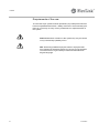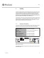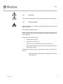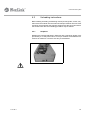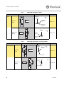
1
Created by EBCCW 00:06
96:05
Created by EBCCW 00:06
5113196-3
Conveyor system X45
User Documentation
Created by EBCCW 00:06
96:05
Created by EBCCW 00:06
96:05
Created by EBCCW 00:06
5113196-3
Conveyor system X45
Created by EBCCW 00:06
96:05
Conveyor system X45
User Documentation
© Flexlink AB 2010
All Rights Reserved
No part of this program and manual may be used, reproduced, stored or
transmitted in any form or by any means without the written permission of
FlexLink Components AB. The contents of this manual are for informational
use only. All information and specifications contained in this document
have been carefully checked to the best efforts of FlexLink Components
AB, and are believed to be true and accurate as of time of publishing.
However, due to continued efforts in product development FlexLink
Components AB reserves the right to modify products and its manuals
without notice.
Created by EBCCW 00:06
FlexLink Components AB assumes no responsibility or liability on any
errors or inaccuracies in this program or documentation. Any kind of
material damages or other indirect consequences resulting from any
FlexLink Components AB´s product part, documentation discrepancies
and errors or non-anticipated program behavior are limited to the value of
appropriate products purchased from FlexLink Components AB. The
products are delivered to the customer at the ’as is’ state and revision level
they are on the moment of purchasing, and are declared in detail in the
license agreements between FlexLink Components AB and user. User
accepts and is obliged to follow the guidelines stated in the separate
license agreement needed in using any parts of this product package.
5113196-3
5113196-3
Preface
Preface
Purpose of this manual
The purpose of this manual is to describe a number of operations that are
intended for the user concerned. Here it becomes clear how the user can
work as well and as safely as possible. By making use of clear illustrations
and texts FlexLink wants to achieve a simple and safe way of working with
the X45 system. This document contains remarks that point out a risky or
specific situation to the user. In many cases this situation is provided with
one of the symbols given below.
General warning for danger!
.
Warning for electrical voltage!
.
Attention, this is an important notice!
.
Compliance with the operations described in this document is important in
order to prevent dangerous situations and unnecessary damage to the X45
system. Carefully keep this document! It is recommended to keep one copy
near the conveyor system and one copy with your technical documentation.
Structure of the manual
Created by EBCCW 00:06
The user’s manual has been composed in such a way, that a number of operations can quickly and easily be found. This manual will not describe operations that are not meant for the user. It does, however, indicate what the
user must do when carrying out a certain operation, for example calling in
technical staff. FlexLink would like to point out to the user that section 1
Safety is to be read carefully.
5113196-3
1
Preface
Requirements of the user
The X45 Conveyor system must be operated by any adult person who has
become acquainted with section 1 Safety. If the user is not technically qualified, he or she may not carry out any maintenance or repair activities on
the system.
.
.
2
Note! Maintenance activities on the system may only be carried
out by a technically qualified person.
NB: Technically qualified employees means: employees that
have followed an adequate training for carrying out the activities
involved and have a good ability to read and understand the
English language.
5113196-3
Safety
1
Safety
The X45 conveyor system has been designed in such a way, that it can be
used and maintained in a safe way. This holds for the application, the circumstances and the instructions described in the manual. Any person
working with or on this system should study the manual and follow the instructions. It is the responsibility of the employer to make sure that the employee is familiar with and follows these instructions.
The company or the country in which the system is used may require extra
safety measures. This particularly applies to the working conditions. This
manual does not describe how these are to be complied with. In case of
doubt, consult your government or safety officer!
1.1
System information
The project number and/or general drawing number shall always be specified when communicating with FlexLink with respect to the module.
Project number
See module nameplate
Supplier
FlexLink Systems Polska Sp z o.o.o
Module type:
See module nameplate
Date of manufacture
See module nameplate
Identification. no.
See module nameplate
Figure 1 Module nameplate
Created by EBCCW 00:06
The modules nameplate is located on the module near the electrical motor
for the drive unit.
5113196-3
3
Safety
1.2
The most important safety conditions
At the moment that the X45 system is going to be operated by a user, the
following safety conditions must be met:
•
Only persons who have read and understood the operating instructions are allowed to operate, maintain and clean the system.
•
Provide good ambient lighting to enable the operator to work well
and orderly with the system.
1.2.1
.
•
Incorrect use of the equipment can cause personal injury.
•
Do not wear clothing or other articles that can fasten.
•
Follow the instructions in this user manual when transporting the
machine. FlexLink Components AB must approve all modifications or changes to this system.
•
Only use recommended spare parts.
•
Only authorised personnel may open electrical units.
•
FlexLink is not responsible for damage if service on the equipment is not performed in accordance with this user manual.
1.2.2
.
4
General
Service technicians
Service technicians must have:
•
Sufficient knowledge for reading technical information
•
Ability to comprehend technical drawings
•
Basic knowledge of mechanics
•
Sufficient knowledge in the use of hand tools
5113196-3
Safety
1.2.3
.
Electricians
Electricians must have:
•
Experience from similar installations
•
Sufficient knowledge to work from drawings and wiring diagrams
•
Knowledge of local safety regulations for electrical power and automation
To avoid risks, only experienced personnel with technical knowledge and
experience may perform repair work on the electronics components.
1.2.4
Created by EBCCW 00:06
.
5113196-3
Operators
To correctly use the equipment, operators must have appropriate training
and/or experience.
5
Safety
1.3
Description of safety provisions
Before putting the system into operation some safety provisions are to be
taken care of. The purpose of these safety provisions is to protect the user,
the product and the system against undesired situations (damage). Without
these safety provisions FlexLink cannot give a guarantee on any damage
caused in absence of these safety provisions.
The table below gives a general description of the safety provisions required. Here it should be noted that only technically qualified employees
are allowed to work on the settings of the safety provisions!
Control
Remark
Emergency stop switch
It is recommended that the X45 conveyor system should be provided with
one or more emergency stop switches that can be operated within reach
of the user.
The switch must have the standard red colour.
Motor protection
6
Should the motor be overloaded for certain reasons, this should be
detected. Without this protection there is a chance that the Motor or other
components of the X45 system will be damaged.
5113196-3
Safety
...
.
1.3.1
Noise level
The noise level produced by the X45 conveyor system is under 65 dB(A).
1.3.2
.
Electrical cabinet
Ensure that the electrical cabinet is closed and locked after working in the
electrical cabinet.
Never bypass the safety system.
Before working in the electrical cabinet, the main switch to the motor must
be turned off and locked. The key is retained by the service technician until
work is finished.
Examples of service work include:
•
Disconnection of wiring
•
Replacement of motors, etc.
•
Service work in the electrical cabinet, terminal boxes, etc.
•
Service work performed on the machine that cannot be seen from
the electrical cabinet.
For adjustment of photo-electric cells, inductive sensors, etc., power is required:
Created by EBCCW 00:06
-
5113196-3
Stop the system and wait until the moving parts have come to
a complete stop.
7
Safety
1.4
Safety measures to be taken
For a safe operation of the conveyor system a number of safety measures
are to be taken. These include the following measures:
•
8
Clean floor surface - With a clean floor surface the operator will
not be hindered while operating the system. This can prevent tripping or slipping, so that the operator does not unexpectedly come
into contact with the system.
5113196-3
Technical specification
2
Technical specification
2.1
Technical characteristics X45
Beam width
45 mm
Chain width
43 mm
Chain pitch
12,7 mm
Drive unit capacity
100- 200 N
Chain tension limit
100-200 N
Item width
10-100 mm
Maximum conveyor length
6m
Maximum weight on conveyor
30 kg
Maximum load per 100 mm conveyor length (see picture below)
800 g (100 g/ link)
Maximum single item weight, horizontal transport (see picture
below)
800 g
Conveyor speed
5-20 m/min
Horizontal bends:
30°/45°/90°/180°
Radius 150 mm
Note! Maximum 2 bends/conveyor
Vertical bends:
5°/15°
Radius 400 mm
Note! 2 bends/conveyor
Electrostatic discharge feature (ESD)
Example:
Max permissible
product weight 200 g
Standard/conductive
Max permissible puck weight
(base, fixture, product )
Max 250 g/ puck
Max
100 g/ link
Puck Ø 43,7
Max permissible single item weight 800 g
Created by EBCCW 00:06
>= 100 mm (8 links)
5113196-3
9
Technical specification
2.2
Operating conditions
The circumstances under which the X45 conveyor system can be applied
partly depend on the materials selected. FlexLink has defined a number of
parameters within which the system would be allowed to function. Should
the system still be applied beyond these limiting values, FlexLink cannot
guarantee the good functioning of it.
10
Ambient temperature (in operation)
-20° to +60°C
During transport / storage
5 to +40°C
Relative air humidity (RH)
10% to 95%, not condensing
Lighting
Normal ambient lighting
5113196-3
Functions
3
Functions
3.1
Motors
The control system of the platform X45e is structured in an object oriented
way. All motors in the platform have embedded control units and local sensors are connected directly to each motor unit. This layout gives a big advantage regarding software developing, electrical design and electrical installation.
3.1.1
Function control
The motor unit consists of a motor, circuit boards and eight connectors in
an encapsulated housing. There are two types of motor units, the drive unit
and the function unit. All that differs on these variants are the motor and the
mechanical housing.
The drive unit has a permanent magnetic (PM) motor and the function unit
has a stepper motor with an analogue position feedback sensor. An embedded microprocessor is dedicated for the application control. Local sensors are connected directly to this unit.
The motors can be autonomously controlled only by the input of the local
sensors or controlled from a line controller over a CANopen network.
The motor unit has also a LED on each side indicating its status. If the motors are in autonomous mode they only need power (24VDC) to work properly.
3.1.2
Line control
Created by EBCCW 00:06
If a line controller is used up to 127 motors can be interlinked via an external CANopen network. RFID reader/writers can be connected to the line
controller via a separate network (Profibus, DeviceNet or Ethernet). All dynamic route handling has to be implemented in the line controller.
The main electrical cabinet supplies the motor units with power, 24 VDC.
The power is divided in safe and continuous power in order to have the possibilities to implement emergency or safety stops
5113196-3
11
Functions
3.2
Diverters, Mergers, Combined Diverter/
Mergers, Transfers, Stop and Locating
station for Puck handling
3.2.1
Diverters
Diverters are used to split a flow of pucks from one line into two. The lines
can be parallel or in a 90° angle.
DL
DR
DL
DR
90°
90°
The diverter is an active unit with one infeed and two outfeed conveyors.
There are four different variants of the diverter.
12
•
Diverter, Parallel, Left
•
Diverter, Parallel, Right
•
Diverter, 90°, Left
•
Diverter, 90°, Right
5113196-3
Functions
Figure 2
Diverter, parallel and 90°
The unit has two positions for photoelectric sensors. The first one is used
for sensing the queue status of the infeed conveyor. This sensor can be replaced by a RFID read/write head.
When a puck arrives the rotation disc opens up to receive the puck. The
second sensor is used for detecting that the puck has reached the gap of
the rotation disc. This is the trigger signal for the main rotation of the rotation disc, with a puck in the gap.
Created by EBCCW 00:06
The decision of which outfeed conveyor to release the puck on can be received from the external bus, via a local sensor or from a predetermined
pattern.
5113196-3
13
Functions
3.2.2
Mergers
Mergers are used to combine the flow from two lines into one. The lines can
be parallel or in a 90° angle.
ML
MR
ML
MR
90°
90°
The merger is an active unit with two infeed and one outfeed conveyor.
There are four different variants of the merger.
•
Merger, Parallel, Left
•
Merger, Parallel, Right
•
Merger, 90°, Left
•
Merger, 90°, Right
Figure 3
Merger parallel and 90°
The unit has two sets of guide brackets each containing two photoelectric
sensors. The first sensor position on each side is used for sensing the
queue status of the infeed conveyors. These queue sensors are the trigger
signal for the merger to moving the rotation disc to one of the two receive
positions. This is done either clockwise or counter clockwise depending on
which conveyor to receive pucks from.
The last sensor is used for sensing pucks in the gap of the rotation disc.
This is the trigger signal for the main rotation of the rotation disc, with a
puck in the gap. When the rotation disc has reached the release position
the cycle is complete and the unit waits for a new puck to arrive.
14
5113196-3
Functions
3.2.3
Combined Diverter/mergers
A combined diverter/merger are used to create a sub line for example to
guide pucks out and in on a satellite conveyor from the main conveyor.
They can also be used as "shortcuts".
Figure 4
CL
CR
CL
90°
90°
180°
CR
L
180°
R
Combined Diverter/Merger 90° and 180°
Created by EBCCW 00:06
This function has the behaviour from both the diverter and the merger. The
prioritized order can be predetermined or decided dynamically from a line
controller.
5113196-3
15
Functions
3.2.4
Transfers
Transfers are used to transfer the puck between the conveyors in a system.
The parallel transfers are passive but the 90° and 180° angled transfers are
driven by a motor.
PL
PR
L
R
L
R
90°
90°
180°
180°
There are six different variants of the transfers.
•
Transfer, Parallel, Left
•
Transfer, Parallel, Right
•
Transfer, 90°, Left
•
Transfer, 90°, Right
•
Transfer, 180°, Left
•
Transfer, 180°, Right
Figure 5
16
Transfer, parallel, 90° and 180°
5113196-3
Functions
3.2.5
Stop
The stop unit is an active unit acting on a single conveyor.
The unit has only one photoelectric sensor. This detects a puck in the
queue. The default position of the stop unit is closed, i.e. it is able to resist
a queue of puck. If the stop is deactivated the unit opens up to receive a
puck.
Directly after the unit has opened up it closes and releases the received
puck. This unit can be controlled either via the external bus or in local mode
by a signal in the local digital input.
Created by EBCCW 00:06
Figure 6
5113196-3
Stop unit
17
Functions
3.2.6
Locating station
The locating Station is an active unit acting on a single conveyor.
The station has only one photoelectric sensor. This is detecting that the
puck has reached the gap of the rotation disc. The locating station can also
be equipped with a RFID read/write head on the locating position. The station can be controlled either via the external bus or using only local control.
Figure 7
Locating unit
62,4
The rotating disc guides the puck sideways out of the conveyor into the locating position. A spring function included in the rotating disc presses the
puck towards a v-shaped block. In this position the puck is locked vertical
and can take limited vertical forces e.g. unload or load a test tube. No loads
are aloud in the X, Y-plane. Locating accuracy is ±0,5 mm.
18
5113196-3
Functions
3.3
Maximum permissible weight
Load
gr
3000
2500
2000
1500
1000
500
5
10
20
15
Speed m/min
Created by EBCCW 00:06
Figure 8 The diagram shows the maximum permissible weight of a group of pucks (product
weight + puck weight) that the functions Divert, Merger, Combined Diverter/Merger,
Stop and Locating station are capable stopping, as a function of the conveyor speed.
5113196-3
19
Unload the X45 system
4
Unload the X45 system
4.1
Preparation
This section describes the steps that are required for unloading the modules for the X45 system.
Note! The operations concerned are to be carried out calmly in
order to be able to carefully monitor any movement of the X45
module.
Before starting the unloading a good preparation is required. The appropriate devices must be available. Apart from that the first transport check is
an important part of the unloading, as in case of damage this should be
mentioned on the delivery note in relation to guarantee and the like.
The first transport check after arrival of the modules a transport check is to
be carried out. The check can be carried out at the moment the module has
been unloaded from the container or the truck. The technical specification
gives the dimensions to be checked. Is the module delivered undamaged
and is it the correct module?
Module serial number type plate with
configurator string
.
20
Note! Any damage is to be mentioned on the delivery note and
should immediately be reported to the supplier. This with respect
to the guarantee of the module.
5113196-3
Unload the X45 system
4.2
Unloading instructions
Before starting unloading, all fastening means (securing belts, screws, etc.)
that secure the module unto the means of transport must be removed. Subsequently check whether the transport supports are still connected well to
the module. After this the unloading procedure may be started.
4.2.1
Shipment
Modules are normally delivered in flat boxes with a maximum length of approximately 3 m. See photo below. Conveyor modules will be delivered in
sections of maximum 3 m which are easy to reassemble.
Created by EBCCW 00:06
..
5113196-3
21
Mounting, installation, adjustment
5
Mounting, installation, adjustment
This section deals with the operations to have the modules function well
within a (transport) system.
Longer conveyor modules (approx >3m) are delivered in sections. The sections are marked up and can easily be joined together. Also the corresponding conveyor chain is marked up and has to be assembled according
to section 5.2.
5.1
Provisions to be provided
Make sure before assembly that the surroundings are clean and free from
obstacles and the mounting surface is clean and level. Besides, it should
be repeated that the operations are to be carried out in a calm and controlled way!
After having placed the modules in the correct position, the modules is to
be fastened to the mounting surface by using the holes in the adjusting
feet.
22
5113196-3
Mounting, installation, adjustment
5.2
Mounting chain to X45 conveyor modules –
Idler end
5.2.1
Tools
Allen key
3 mm
Pin insertion tool
Screwdriver
5.2.2
Procedure
1 Use the screwdriver to remove the plastic cap on
the idler end. Loosen the screws on both side on
the basic unit, use a 3 mm Allen key.
Created by EBCCW 00:06
2 Remove the sideplates, use a screwdriver.
5113196-3
23
Mounting, installation, adjustment
3 Feed the chain into the conveyor until it reach the
drive wheel at the driving end.
CAUTION! Check the feed direction of the chain
4 Continue to feed the chain around the drive
wheel into the return part of the beam.
5 To avoid noise the number of links in the chain
shall be adjusted so that a slight pretension is
obtained.
CAUTION! Make sure that the chain enters the
drive wheel correctly.
6 Use a pair of slip joint pliers to insert the pin halfway into the chain link.
7 Join the chain ends.
8 Press the pin through the chain.
9 Make sure that the pin snaps in to the correct
position (centered).
24
5113196-3
Mounting, installation, adjustment
5.3
Assembly of modules
The modules are to be assembled according to the system layout.
Find the correct position for connecting modules using the measurements
in section 5.3.3 on page 28 to section 5.3.8 on page 32
When assemble the parallel conveyors use the beam spacer XUCD 15x20
(see picture below). The distance between the spacers is to be approximately no more than 600 mm
Note that it is very important that the modules lines up horizontal according
to picture (A) below.
To avoid incorrect readings from the sensors that are used for detecting the
puck, guide rails must be mounted transversely to the beam, according to
picture (B) below.
Created by EBCCW 00:06
A
5113196-3
B
25
Mounting, installation, adjustment
5.3.1
Slide rail cutting, RFID
Slide rail cutting to clear RFID when placed between two parallel conveyors
at C-C 60 mm. See picture below.
1.
511
269
5
A
A
64
A-A
Cut to here
2.
5112
69
5
26
5113196-3
Mounting, installation, adjustment
5.3.2
Wiring
BUS A1
BUS A1
BUS A2
BUS A2
DI 4
DI 4
DI 3
DI 3
DI 2
DI 2
DI 1
DI 1
PWR
PWR
BUS B
The functions motors are to be connected according to picture below and
mounting instructions section 5.3.3 on page 28 to section 5.3.8 on page 32.
BUS B
Created by EBCCW 00:06
1
Markings on plate
Explanation
PWR
Power in
Connect power cable
BUS B
Internal bus
Used for parameter settings
DI 1
Digital input 1
Sensor, connect if used, see section 5.3.3 on page 28 to
section 5.3.8 on page 32
DI 2
Digital input 2
Sensor, connect if used, see section 5.3.3 on page 28 to
section 5.3.8 on page 32
DI 3
Digital input 3
Sensor, connect if used, see section 5.3.3 on page 28 to
section 5.3.8 on page 32
DI 4
Digital input 4
Sensor, connect if used, see section 5.3.3 on page 28 to
section 5.3.8 on page 32
BUS A1
External bus in
Connect this if external CANOpen network is used
BUS A2
External bus out
Connect this if external CANOpen network is used
5113196-3
27
Mounting, installation, adjustment
The following schematic presentation shows how the various modules are
combined to form a complete X45 conveyor system, mechanical installation as well as the electrical interface are showed.
5.3.3
Mounting instruction, Diverter
Function
Designation Assembly mechanical/electrical
Divert
XUUT DL
Angularity
Item 1,2
1
Parallel (Left)
DI 3
2
Home
position
Release
angle 2
Release
angle 1
+
(XUUT DL 1)
(XUUT DL 2)
Receive angle 1
XUUT DR
1
(Right)
Release
angle 1
Home
position
Release
angle 2
+
(XUUT DR 1)
DI 3
(XUUT DR 2)
2
Receive angle 1
Divert
XUUT 90 DL
90°
(Left)
1
2
DI 3
22
Release
angle 1
(XUUT 90 DL 2)
Receive angle 1
1
(Right)
DI 3
2
+
Release
angle 1
Home
position
22
Receive angle 1
28
(XUUT 90 DL 1)
Home
position
Release
angle 2
XUUT 90 DR
+
(XUUT 90 DR 1)
(XUUT 90 DR 2)
Release
angle 2
5113196-3
Mounting, installation, adjustment
5.3.4
Mounting instruction, Merger
Function
Designation Assembly mechanical/electrical
Merge
XUUT ML
Parallel
Left
Angularity
1
2
DI 4
Item 1,2
Home
position
DI 3
(XUUT ML 1)
DI 2
DI 1
(XUUT ML 2)
Receive angle 2
XUUT MR
1
Right
2
DI 3
DI 4
DI 1
DI 2
Release
angle 1
Receive angle 1
Home
position
XUUT 90 ML
90°
Left
DI 2
(XUUT MR 2)
Receive angle 2
DI 4
145
1
DI 4
DI 2
145
DI 3
(XUUT 90 ML 1)
(XUUT 90 ML 2)
Receive angle 1
Release
angle 1
Home
position
2
+
Home
position
DI 1
Right
Release
angle 1
Receive
angle 2
DI 3
2
XUUT 90 MR
+
(XUUT MR 1)
Receive angle 1
Merge
+
Release
angle 1
Receive
angle 2
+
(XUUT 90 MR 1)
(XUUT 90 MR 2)
Receive angle 1
Created by EBCCW 00:06
DI 1
5113196-3
29
Mounting, installation, adjustment
5.3.5
Function
Designation
Combined
Diverter XUUT 180 CL
/Merger (Left)
Parallel
Mounting instructions, Combined Diverter/Merger
Assembly mechanical/electrical
DI 2
Angularity
1
Item 1,2 and 3
Home
position
Receive angle 2
DI 4
DI 3
57
DI 1
Release
angle 1
+
(XUUT 180 CL 1)
(XUUT 180 CL 2)
Release
angle 2
Receive angle 1
2
XUUT 180 CR
DI 2
1
(Right)
DI 3
DI 4
DI 1
57
Release
angle 1
Home
position
Receive angle 2
+
(XUUT 180 CR 1)
(XUUT 180 CR 2)
Receive angle 1
Release
angle 2
2
Combined
Diverter XUUT 90 CL
/Merger (Left)
DI 2
DI 4
3
90°
1
DI 3
DI 1
2
XUUT 90 CR
(Right)
22
1
DI 3
DI 4
3
22
Release
angle 2
(XUUT 90 CL 1)
(XUUT 90 CL 2)
(XUUT 90 CL 3)
Receive angle 1
Release
angle 1
Receive
angle 3
Home
position
2
+
Home
position
DI 2
DI 1
30
Release
angle 1
Receive
angle 3
+
(XUUT 90 CR 1)
(XUUT 90 CR 2)
(XUUT 90 CR 3)
Receive angle 1
Release
angle 2
5113196-3
Mounting, installation, adjustment
5.3.6
Mounting instructions, Transfer
Function Designation
Assembly mechanical/electrical
Transfer
2
Parallel
Angularity
Item 1,2
XUUT PL
(XUUT PL 1)
(Left)
(XUUT PL 2)
1
2
XUUT PR
(XUUT PR 1)
(Right)
(XUUT PR 2)
1
Transfer
90°
2
XUUT 90 L
Release
angle 2
Home
position
+
DI 1
(XUUT 90 L 1)
(Left)
(XUUT 90 L 2)
Receive angle 1
1
Home
position
2
DI 1
XUUT 90 R
Release
angle 2
+
(XUUT 90 R 1)
(Right)
(XUUT 90 R 2)
1
Receive angle 1
Transfer
Home
position
180°
+
XUUT 180 L
(XUUT 180 L 1)
DI 1
(Left)
Release
angle 2
1
2
(XUUT 180 L 2)
Receive angle 1
Home
position
+
XUUT 180 R
(Right)
(XUUT 180 R 1)
DI 1
(XUUT 180 R 2)
Created by EBCCW 00:06
1
5113196-3
2
Receive angle 1
Release
angle 2
31
Mounting, installation, adjustment
5.3.7
Function
Designation
Mounting instructions, Stop
Assembly mechanical/electrical
Angularity
Item
Home
position
Stop
+
Release
angle 1
DI 1
XUUS 11 L
XUUS 11 L
(Left)
Receive
angle 1
Home
position
XUUS 11 R
DI 1
+
Release
angle 1
(Right)
XUUS 11 R
Receive
angle 1
5.3.8
Function
Designation
Mounting instructions, Locating station
Assembly mechanical/electrical
Angularity
Home
position
Locating station
DI 1
XUUL 11 L
Release
angle 1
Item
+
XUUL 11 L
(Left)
Receive angle 1
XUUL 11 R
DI 1
Release
angle 1
Home
position
+
XUUL 11 R
(Right)
Receive angle 1
32
5113196-3
Mounting, installation, adjustment
5.4
Adjustment
5.4.1
Parameter setting tool
All software in the X45e motors are preloaded and the behaviour of
the motors can be adjusted to different performance (such as function type,
speed and angle settings) by a parameter setting tool kit, 5113070
For more information see "User documentation, Parameter setting tool" on
flexlink.com and "Technical library".
Created by EBCCW 00:06
.
5113196-3
33
Technical maintenance
6
Technical maintenance
6.1
Maintenance intervals
Within the application, where X45 equipment is normally used, environmental conditions are clean compared to many other FlexLink system installation sites. During these conditions X45 modules normally require a
minimum of maintenance.
The following maintenance interval is recommended for X45 equipment:
•
An inspection for all equipment is recommended regularly every
1500 operating hours or every 3rd month depending on which
case that occurs first.
Table 1: Interval
Interval
1-shift
Every 3:rd month
2-shift
Every 3:rd month
3-shift
Every 1500 hours
In case of less clean environmental conditions certain wear can occur and
more frequently planned maintenance intervals are recommended. If this
is the case, consult your FlexLink supplier.
34
5113196-3
Recommended spare parts
7
Recommended spare parts
Created by EBCCW 00:06
See separate Spare parts list on flexlink.com and "Technical library"
5113196-3
35
Supplier’s information
8
Supplier’s information
This manual goes together with the module of the type mentioned on the
order and on the title page of this manual. This document was drawn up by:
FlexLink Components AB
Date: 2010/01/18
Copyright: FlexLink Sweden, 2010
The machine was produced by:
Flexlink Components AB
Tel:
+46 (0)31-337 31 00
SE-415 50 Göteborg
Fax:
+46 (0)31-337 31 95
Sweden
E-mail:
[email protected]
www.flexlink.com
.
36
Note! In case of failures please contact the system integrator.
5113196-3
Supplier’s information
EC Declaration of Incorporation
Partly completed machinery
FlexLink Components AB
SE-41550 Göteborg
Sweden
We hereby declare that the following equipment is intended to be incorporated into a FlexLink conveyor system and thereby forming a machine. Operation is prohibited until it has been determined that the machine in which
these products are incorporated, has been declared in conformity with the
Machinery Directive 2006/42/EC, together with amendments which have
entered into force as of the date of issue of this declaration, with particular
reference to the essential health and safety requirements in connection
with the design, construction and manufacture of the below specified
equipment.
Conveyor modules X45
-
XUUC S, XUUC SP
-
XUUC V, XUUC VP
-
XUUC L, XUUC LP
-
XUUC U, XUUC UP
Corresponding EC directives:
Low Voltage Directive 2006/95/EC
According to 2004/108/EC Electromagnetic Compatibility Directive (EMC),
the listed device is not independently operable product, but intended as
part of a given fixed installation. Compliance of the directive requires the
correct installation of the product, the observance of specific installation
notes and product documentation.
FlexLink Components AB
Flexlink Components AB
Svante Anderholm
Anders Jonsson
Chief Operating Officer
Responsible Technical file
__________________________________________________________________________
FlexLink Components AB
Created by EBCCW 00:06
Telephone: +46-31-337 31 00
Fax: +46-31-337 22 33
www.flexlink .com
5113196-3
SE-415 50 Göteborg
Sweden
37
Supplier’s information
38
5113196-3