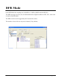
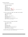
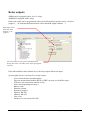
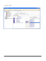
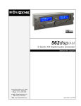
1
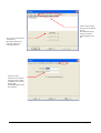
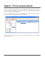
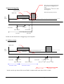
User's manual of the APRWIN64 software
for Windows
(Measurements processing and transmission software for the APR64)
dfv Technologie
Z.A. Ravennes-les-Francs
2 avenue Henri Poincaré
BP 80009
59588 BONDUES CEDEX
FRANCE
Tel : 33 (0)3.20.69.02.85
Fax : 33 (0)3.20.69.02.86
03/06/2013 Edition
Email : [email protected]
Site Web : www.dfv.fr
Table of contents
Information ........................................................................................................................... 4
Installation............................................................................................................................. 5
General Description ............................................................................................................. 6
Overview of the Software.................................................................................................... 7
Configuration Menu ............................................................................................................ 8
Creating a new unit............................................................................................................ 10
Creating a unit APR64 .................................................................................. 10
Creating measurement folder........................................................................ 12
Connection to APR64 ........................................................................................................ 14
Import / Erase measurements .......................................................................................... 15
Analyzing data on the PC ................................................................................................. 16
Quick Start .......................................................................................................................... 17
Triggers et recording ......................................................................................................... 18
DFR Mode ........................................................................................................................... 23
Programming the APR64................................................................................................. 24
Programming the APR64.................................................................................................. 25
Analog channels programming..................................................................... 27
Parameter of the digital channels.................................................................. 30
Channels groups (single, bi, and triphase) ................................................... 32
Frequency reference ...................................................................................... 33
Relay outputs ................................................................................................. 34
Setup of DFR mode....................................................................................... 37
Creating calculated values ............................................................................ 39
Setup of Threshold on analog or calculated channels. ................................ 40
OR FUNCTION............................................................................................. 41
AND FUNCTION ......................................................................................... 42
Sending the program to the APR64.............................................................. 43
Information • 2
Display in real time ............................................................................................................ 44
Display APR64 Status................................................................................... 45
Display of triggers ......................................................................................... 46
Display of RMS values ................................................................................. 47
Display of digital channels............................................................................ 48
Display of harmonics (Graphic mode)......................................................... 49
Display of harmonics (Numerical) .............................................................. 50
Display of single phase Power...................................................................... 51
Display of Triphase power............................................................................ 51
Display of Triphase power............................................................................ 52
Display of symetrical components ............................................................... 53
Display profile..................................................................................................................... 54
Single and 3 phases groups........................................................................... 58
User formulas................................................................................................. 59
Display of measures ........................................................................................................... 62
Overview ........................................................................................................ 62
Display curves................................................................................................ 68
Displaying of values (Vrms, Harmonics, Powers …) ................................. 69
FTP connection ................................................................................................................... 70
Appendix 1 : files structure ............................................................................................. 71
Appendix 2: APRWIN64 Workspace ............................................................................. 72
Appendix 3 - File format ................................................................................................. 73
Appendix 4 - Sign convention.......................................................................................... 76
Glossary ............................................................................................................................... 77
Information • 3
Information
The use of the APRWIN64 software requires a good knowledge of the APR. If
not, we advise you to refer to all own user's manuals :
•
User's guide of APR64
•
User's guide of APR64M
•
User's guide of Time synchronization for APR64 / APR64M
•
User's guide for measurement unit BFOP2
•
User's guide for Digital Remote Unit DRU
•
Install guide for APR64
•
First-start guide for APR64
APRWIN Software is protected against copy by laws but you are authorized to
install this software on several PC (A desktop PC and a portable PC for example).
Minimal configuration for using APRWIN64
•
Centrino Duo
•
Windows XP
•
2Go Ram
•
40Go of free disk
•
Graphic card 1024 x 768
•
DVD Burner
•
Deskjet or Laserjet printer A4
Caution : Sometimes the administrator locks the access of your PC (registers …). In this case
APRWIN64 may causes some bugs. In case of problem, ask your administrator to modify the
access of your PC.
Information • page 4
Installation
Insert the DVD or CDROM into the DVD-Player to start the software installation
on your PC. If the AUTORUN mode is confirmed on your system, the installation
is going to start automatically, otherwise it will be necessary to execute
SETUP.EXE program from the DVD/CDROM
Then, follow the instructions of the set-up program (It is advised not to change the
paths and names by default).
Note : The installation of a new version does not requires an uninstallation.
At first running, the software asks to enter a key. Enter the user name and the key
supplied with the DVD/CDROM (The key is notified on the last page of the user's
guide).
Notes :
- Enter small letters / capital letters for required key and name.
- You can not use the "O" letter for the software key.
The directory of installation is \program files\aprwin64.
If you want to backup the configuration, copy only this directory. All the setup is
stored in it.
Installation • page 5
General Description
The APRWIN64 allows you to drive APR64 DFR and APR64M Analyzers with a
PC equipped with Windows operating system.
The APRWIN software lets you :
•
To drive independently all the APR64(M)
•
To display measurements of APR64(M) in real time
•
To analyze the measurements of APR64(M)
•
To analyze the measurements of the APR8, APRV, APR16, APR4U4I and
ELODI (option).
•
To analyze COMTRADE file (ASCII or BINARY) (options)
•
To export the data in COMTRADE (option) or EXCEL
•
To make reports (with WORD for exemple) using copy/paste function.
General Description • page 6
Overview of the Software
When starting the software display the site manager.
The manager allows you to access all the menus and functions (Configuration, setup,
communication, display, printing …)
Management of the APR64 (Connection, programming, real time …)
Management of the measurements(display curves …)
Connection indicator
Overview of the Software • page 7
Configuration Menu
This menu allows to setup work directory, logo and password.
By default the
parameters are stored in
the Data directory.
Choice of the logo file.
By default (if empty)
the DFV logo is used.
Configuration Menu • page 8
You can choose more than
one directory
Be carefull, directories
cannot be defined on
removable devices.
Choice of the storage
directory for each kind
of unit.
The default directory
will be used when
importing data to the
PC.
The access at the
Software can be locked
with a password. When
locked the user can only
display data
(Programming and erase
not possible).
Configuration Menu • page 9
Creating a new unit
In order to communicate and programming an APR64(M), you need to create it in the database of
the DFR List.
"Measurement folder" allows to analyze measurements files (APR64, APR16, ELODI, CSV and
COMTRADE files) (Options).
Creating a unit APR64
serial #
Enter
configuration key
of the APR64
Enter user name
The configuration of the APR64 is displayed
according the key.
The key and user name are given by DFV when buying the APR64. In case of upgrade or option
DFV give you a new one.
This key determines the configuration of the APR64 (number of active channels, number of digital
racks, type of channels BFOP or DRU).
After validation the APR64 is created in the DFR manager (See following page).
Creating a new unit • page 10
When creating a unit APR64, it is necessary to enter parametrers (IP adresse, storage place …).
These caracteristics will be used to configurate the APR64.
Thes caracteristics are stored in an USB key. When starting the first time, APR64 reads the USB key
and then configures itself.
APR64
parameters
Communication ports to be
configured in order to access
to the APR64.
FTP server
parameters
Validate to erase
internal memory after
copy on an USB key.
Validate to erase
internal memory
after storage on FTP
server
Note : Programming the APR64 using an USB key is only necessary the first time. When the IP
address of the APR64 is set, the PC can communicate with the APR64.
Creating a new unit • page 11
Creating measurement folder
Measurement folders allows to collect the data files from the different kind of units
(APR64, APR4U4I, APR16, APRV) or from other manufacturers in option
(COMTRADE file).
Type of file
Name of the
folder
Number of synchronized units
Storage of measurements on APR64
Recorded measures are stored on the PC at the place defided in the configuration menu. This place
be local or remote (on a data server)
The APR64 measurements files have this structure :
aaaammjj.rep\aaaammjj_hhmnsscs_ ……. . dat, hdr,cfg for the original files and .tar.gz for the
compressed files.
The APRWIN64 Software can deal with either original files or compressed files.
The files are organized like that in APRWIN64 Software :
Name folder
YEARMONTH
DAY1
DAY2
Creating a new unit • page 12
In order to see the measurement file list, you only have to click on the desired folder
Name of folder
Storage place
Trigger condition
The synchronization of the different files when a folder is composed of more than one unit is done
automatically by APRWIN64 Software.
Note : Each import module (APR16,COMTRADE …) is licenced (Option)
Creating a new unit • page 13
Connection to APR64
The link between the APR64 and the PC is done by Ethernet (TCP-IP)
To connect, choose the unit and then click on the connection icon.
Click to start and stop the connection
Internal
memory of the
APR64 is here
Direct connection
using APR64
parametrers
Connection using
manual or router
parameters
Port used by the APR64
Green : OK
Off : Error
Note : In case of using a router, indicate the external address (internet address) and the port
configured in the router (to access to internal address).
84.10.121.96 / port 24 extern is equivalent to internal address 192.168.1.47 / port 24
….
As soon as the link is ok, the PC can :
-
Import the measurements from APR64
Erase the measurements in APR64
Parametrer the APR64
Display measurements in realtime
Manual trig the APR64
Read and setup the time
Connection to APR64 • page 14
Import / Erase measurements
In order to import/erase measurements stored on the APR64, you need to connect to the unit and
then choose measures (APR64 memory) folder. Choose the year, month and day and then choose the
files(s) to be imported/erased and right click
Note : At the beginning of the connection, the APRWIN64 software updates the Folder "Measures".
It can take some time depending of the speed of the connection.
When the files have been choosen, the measures are stored in the default place on the PC defined in
the configuration menu.
Import / Erase measurements • page 15
Analyzing data on the PC
APRWIN64 Software allows to analyze measurements files from APR64, APR16, APR8,
APR4U4I, APRV, ELODI and COMTRADE files
Display module can show DFR or Trend mode event. It allows to display simultaneously many files
at the same time.
Choose one or more files in the folder and right click to view the measurements (Or double click on
one file)
Analyzing data on the PC • page 16
Quick Start
In order to start an APR64 you need :
-
Create an "APR64" in the "unit" manager using informations given by DFV (serial #, user
name, key).
Create un local parameter on the PC
Connect the measurements on the APR64
For the first use :
o Copy the parameter file on the USB key
o Connect the USB key to the APR64
- Power on the APR64 and let it upgrade with the usb key.
- Connect APR64 with Ethernet
- Export parameters from the PC to the APR64 le paramétrage vers l'APR64 (If not done by
USB key)
- Verify in the real time menu that all measures are correct no trigger is active
- Start the trigger ("Enable trigger" button)
To get the measures done by APR64 :
-
Connect to the APR64 (Ethernet)
In the unit manager open the folder "measure (APR64 memory)"
Select one or more file to be imported
Right click "import on PC"
Measurements will be imported on the place defined as default in the setup menu.
Quick Start • page 17
Triggers et recording
DFR or Trend mode
The APR64 can be programmed to record event when a threshold is reached (under, over, relative)
for an analog (RMS, Power …) or a digital channel.
The record can be programmed on the begin of the fault and/or the end the fault. (Normal to fault
state / Fault to normal state)
For each record, the DFR records a pre-time and a post-time.
The recording duration can also be expanded if a new event occurs during the post-time
(retriggering).
In order to avoid to saturate the APR64, the duration is limited by the maximum post-time duration.
Events can be filtered, and the DFR can be inhibited if the duration of the event is too short.
Another security can be programmed on the DFR. The recording can be inhibited if the time
between the end of an event and the following one is too short (interval before retriggering).
Recording can be inhibited by a OR condition (Maintenance position programmed on a digital
channel for example)
Example of a programming for the DFR mode
Triggers et recording • page 18
1) Threshold on reaching
RMS
Hysteresis
Max
value
Threshold
Filter time
Return to normal
T0
(Trigger)
Start of fault
End of fault
Pre-time
Post-time
In this case, a max threshold is reached, the APR64 detects this threshold immediately but do not
trig immediatly. In order to trig, the event must be longer that the filter time
If the event if longer than the filter, then the pre-time is set and the recording starts up to the posttime.
2) Threshold on return
Return to normal
Max
value
Filter time
T0
(Trigger)
Pre-time
Post-time
Triggers et recording • page 19
3) Cycle with retriggering limited by the max. post-time
RMS value
Duration longer
than time before
retriggering
2nd fault
Max
Value
Threshold
Filter
Return to normal
T0
(Trigger)
Start of the 1st fault
Filter
End of the 1st fault Start of the 2nd fault
Pre-time
1st post-time
End of 2nd Fault
2nd Post-Time
Max duration (Recording time is limited)
The 2nd fault starts in the post-time
of the first one
The APR64 adds a new post-time
and records only one fault up to
the maximum post-time
After the max post-time
records stops
Triggers et recording • page 20
The event is not triggered because
the time before retriggering is to
short.
Otherwise the 2nd fault is too short
to be triggered
4) Ignored retriggering
Time too short
Records stops after post-time
RMS value
Max
Value
Threshold
Return to normal value
T0
(Trigger)
Filter time
Start of fault
End of fault
Pre-time
Post-time
In this case the time befrore retriggering is not complied
5) 2 different faults
RMS value
Max
value
Threshold
T0
(Trigger)
Filter time
Start of 1st fault
Pre-time 1st fault
Return to normal value
T0
(Trigger)
Filter time
End of 1st Fault
Start of 2nd fault End of 2nd Fault
Post-time 1st fault
Post-time 2nd fault
Post-time 2nd fault
In this case the pre-time of the second fault is common with some time of the 1st fault
Triggers et recording • page 21
6) Trigger on digital channels (low to high)
L1 ↑
or
L2 ↑
Trigger
Filter time
Pre-time
Trigger
Post-time
Trigger
Time is lower than filter time. Fault is not triggered.
Filter-time allows to eliminate bad triggers.
7) Trigger on digital channels (low to high and high to low)
L1 ↑↓
or
L2 ↑↓
Trigger
Filter time
Filter time
Pre-time
Trigger
Filter time
Post-time
Trigger
Trigger
Trigger
Time lower than filter time à No record .
.
Post-time is postpone as soon as the triggers are present up to maximum post-time
Triggers et recording • page 22
DFR Mode
In the DFR Mode the sampling rate is 6400Hz or 12,8kHz (6400Hz with the BFOP2)
The DFR can trigger on min, max, dx/dt threshold and on digital conditions AND , OR , on the start
or return of the threshold.
The DFR recorder can be triggered by the Trend mode recorder
The number of record for one day can be limited (70 by default)
DFR Mode • page 23
Date, trigger ….
Example of DFR Record
Customized logo
(Menu setup)
Triggered channel
"0" time
Trigger condition
Programming the APR64 • page 24
Programming the APR64
The APR64 is configured by a "param" file. This file is stored on the APR64.
The parametrers of the APR64 is composed of many parts :
-
Parametrers of the analog channels
Parameters of the digital channels
Creating of group of channels (triphase or single phase system)
Frequency reference
For the DFR (Option)
- Creating of analog channels to be measured
- Creating of calculated analog channels (Power, Frequency…)
- Threshold on analog values (measured of calculated)
- Trigger on digital channels
- OR and AND formulas
For each recorder (Option)
- Creating of analog channels to be measured
- Creating of calculated analog channels (Power, Frequency, Harmonics…)
- Threshold on analog values (measured of calculated)
The parameter of the APR64 is done on a PC with APRWIN64 software installed. Then it is sended
to the APR64 with Ethernet link or in an USB key (obligatory the first time)
Programming the APR64 • page 25
The following screen allows to define the global parameters.
APR64 is composed
of 12 channels. Each
channel can be
configured as an
analog or digital
channel.
Channel can be inhibited
Setup of the channel
-
Channels
numbers
site name (folder name)
Mains frequency (50 or 60Hz)
Working range of APR64 is 42,5Hz to 57,5Hz in 50Hz and 51Hz to 69Hz in 60Hz. If frequency is
over these limits, frequency is invalid and setted to the default value (50Hz or 60Hz).
Programming the APR64 • page 26
Analog channels programming
Each analog channel of the APR64 is defined by :
-
Name of the channel (on 19 characters)
Type of channel (Voltage, current, other) AC or DC
Phasis (A,B,C,N, Other)
Unit (Volt, kV, A, ° , bar ….)
Nominal value (=100%)
Start of scale (Measured value) or VTs/CTs primary
End of scale (Measured value) or VTs/CTs primary
Start of scale (Value on input of APR64) or VTs/CTs secondary
End of scale (Value on input of APR64) ou VTs/CTs secondary
Input range used on the unit
20A to measure 4In of a 5A signal
240V for a voltage channel of the BFOP2
Start of scale are 0 if AC
Name of the analog
channel
Enable /
Disable record
of the channel
A1:2=channel #2 of
the BFOP #1
Divide the value
by Square root
of 3.
Nominal value to
allow calculation of
the purcentage
Programming the APR64 • page 27
Exemples of programming :
1) Measure of a 230V voltage with BFOP2
Channel name : mains voltage
Type of channel : Voltage AC
Phasis : A
Unit : Volt
Nominal value : 230V
Start of value scale : 0V
Primary
End of value scale : 230V
Start of input scale : 0V
Secondary
End of input scale : 230V
Range: 240V (End of scale of BFOP2)
Identical values because no VTs
2) Measure of a single voltage on 20000V with Vts 20000V / 100V with BFOP2
Name of channel : VA.TR422
Type of channel : Voltage AC
Phasis : A
Unit : Volt
Nominal value : 11547V (20000/ √3)
Start of value scale : 0V
End of value scale : 11547V (Input of the Vts)
Start of input scale : 0V
End of input scale : 57,7V (100 / √3) (Output of the Vts)
Range : 240V (End of scale of BFOP2)
3) Measure of a current on a CTs 4000 /5A with a BFOP2
Name of channel : IA.TR422
Type de channel : Current AC
Phasis : A
Unit : A
Nominal value : 1000A
Start of value scale: 0A
End of value scale: 4000A (input value of the CTs)
Start of input scale :: 0A
End of input scale :: 5A (output value of the CTs)
Range : 20A (End of scale of BFOP2)
PS : If the 20A range is choosen, The APR64 will be able to measure a current up to 20A
(4x5A) on the CTs secundary 16000A (4x 4000) on primary.
Programming the APR64 • page 28
4) Measure of a temperature (Probe 0-60° to 4/20mA ) with a BFOP2
Name of channel : Transformer Temp.
Type of channel : Other DC
Phasis : Autre
Unit : °C
Nominal value : 30°C
Start of value scale : 0°C
End of value scale : 60°C
BFOP is equipped with a 4-20mA input
Start of input scale : 4mA
End of input scale : 20mA
Range : 20mA (End of scale of BFOP2)
5) Measure of a composed voltage on a 400kV mains with VTs 400kV / 100V with a
BFOP2
Name of channel : UC.TR3
Type of channel : Voltage AC
Phasis : C
Unit : kV
Nominal value: 400kV (100%)
Start of value scale : 0kV
End of value scale: 400kV
Vts 400kV to 100V
Start of input scale : 0V
End of input scale : 100V
Range : 240V (End of scale of BFOP2)
6) Measure of a 48V DC battery with BFOP2
Channel name : U Batterie
Type of channel : Voltage DC
Phasis : Other
Unit : V
Nominal value : 48V (100%)
Start of value scale : 0V
Pirmary=Secundary
End of value scale : 48V
Start of input scale : 0V
End of input scale : 48V
Range : 240V (End of scale of BFOP2)
Programming the APR64 • page 29
Parameter of the digital channels
Each digital channel of the APR64 is defined with these informations :
Name of the channel (19 char)
Name of the high state (1) (19 char)
Name of the low state (0) (19 char)
The digital channels are coded like that :
D01:01 (Digital channel 1 of the rack D01)
D05:03 (Digital channel 3 of the rack D05)
Programming the APR64 • page 30
Note : Each channel (among the 12) can be equipped with 8 digital rack
Even if the racks are not configured, the numbering is done in order a rack can be added after.
Example : APR64 equipped with 4 digital racks and 1 DRU equipped with 7 racks
D01:L1-L16
D02:L1-L16
D03:L1-L16
Local racks
D04:L1-L16
D05-D08 missing
D09:L1-L16
D10:L1-L16
D11:L1-L16
D12:L1-L16
Remote racks
(DRU)
D13:L1-L16
D14:L1-L16
D15:L1-L16
D16: missing
Programming the APR64 • page 31
Channels groups (single, bi, and triphase)
A group is defined with the following parametrers :
Name of the group (19 char)
Type of connection : Star (with neutral)
Triangle (without neutral)
Voltage channels Phasis A, Phasis B, Phasis C
Current channels Phasis A, Phasis B, Phasis C
Voltage neutral
Current neutral
For the Star mode
(With Neutral)
PS : A group can be defined with only 1 or 2 phasis, APR64 will adapt the calculation depending of
the channels available.
Ps : When creating groups "with neutral", APR64 will automatically create UAB, UBC et UCA
values
Example of groups : INCOMING1, OUTCOMING2, BUSBAR1
Programming the APR64 • page 32
Frequency reference
In order to make a reliable measure, APR64 has to be synchronized on the mains frequency.
You have to define a list of voltage on which the frequency can be calculated.
If the frequency disappears on one channel, it is calculated on another one. If there is no valid
frequency, the APR64 uses the frequency defined in the program.
If you need to measure more than one frequency, you can had one uses the following menu (Right
click on "Site" menu.
Programming the APR64 • page 33
Relay outputs
APR64 can be equipped with 4, 8 or 12 relays .
APR64M is equipped with 2 relays.
Each relay output can be programmed with system information (measure active, record in
progress… ) or with threshold information (max threshold, digital channel …)
Signal must occurs
more than "filter
duration" to be
triggered
For every record, the relay goes to WORK STATE
during "min value" and "Max value" if the input signals
stays ON.
If the Min and Max value duration are 0, the relay output follows the input.
System signal can be "connected" to a relay output :
-
Loss of external time synchronization
Error on measurement module (BFOP or DRU) no power or bad fiber optic
FTP Error (No connection with the server)
Power lost (Operating on battery)
Battery weak
Measures started
Record in progress
Memory full 90%
Memory full 95%
New event
Number of event reached for 24H
Programming the APR64 • page 34
Example : Filter=0, Min duration=0, max duration=0
Input channel
Relay output
The relay output follows the input channel
Example : Filter=100ms, Min duration=0, max duration=0
Input channel
80ms
Relay output
The duration of the input channel is too short (<100ms) , the input is filtered and the relay output
don't change.
Example : Filter=100ms, Min duration=0, max duration=0
Input channel
Relay output
110ms
100ms
The relay output goes to High state after the filter of 100ms and then follows the input channel.
Example : Filter=100ms, Min duration=200ms, max duration=300ms
Input channel
Relay output
110ms
100ms
200ms
The relay goes high during 200ms after 100ms (Filter)
Programming the APR64 • page 35
Example : Filter=100ms, Min duration=200ms, max duration=300ms
560ms
Input channel
100ms
300ms
Relay output
The relay output goes high during 300ms after 100ms. The high state is limited to 300ms.
Programming the APR64 • page 36
Setup of DFR mode
State of the trigger (Low to
High or high to low)
-
Filter duration
Setup of the sampling frequency (Fixed to 6400Hz with the BFOP2)
-
Setup of pre-time
-
Setup of post-time
-
Setup of maximum post-time
-
Setup of the limit of file per day (counter reseted every day at 0H00)
DFR record is enabled if the "Trigger OR" function is true.
DFR inhibit if done by the "Inhibit OR"
Caution : Filters take a lot of calculation time. Use them only if necessary.
Programming the APR64 • page 37
Example of inhibit :
Programming the APR64 • page 38
Creating calculated values
DFR can calculate some values from the measured signals.
These values are stored in the files generated by APR64 and can also be used to trig the DFR.
Calculated value available in DFR mode are :
- AND function
- OR function
- RMS value
- Frequency
- Power (active, reactive, apparent, cos, tg …)
- Symetrical components (Voltage and current)
- RMS values of the composed voltage (calculated with single voltages)
Programming the APR64 • page 39
Setup of Threshold on analog or calculated channels.
For each value it is possible to setup :
- Low threshold
- High threshold
- Relative threshold (dx/dt)
Trigger can be programmed low to high (normal state to fault state) or high to low (fault state to
normal state)
Threshold in value or purcentage of the nominal
Name of threshold
PS : It is possible to create more than one threshold for the same value (90% , 70% and 10% for
example)
Programming the APR64 • page 40
OR FUNCTION
D01:L1: name (↓ ) OR
max Threshold UA.TR132 ( ↑ ) OR D02:L16:name (↓ ↑ )
If the channel L1 of the D01 Rack goes to 0 OR if there a max threshold on UA.TR132 OR if the
channel L16 of the D02 Rack goes to 0 or 1 then the OR function is true.
OR function can be used to trigger or inhibit the APR64 or to activate a relay.
Programming the APR64 • page 41
AND FUNCTION
D1:L1:name channel (0) ET D3:L7:name channel (0)
If the channel L1 of the Rack D1 AND L7 of the rack D3 are in low state, then the AND function is
true.
AND function can be used to trigger or inhibit the APR64 or to activate a relay.
Programming the APR64 • page 42
Sending the program to the APR64
Connect the PC and the APR64 (Menu connection)
In the DFR manager, select the APR64 setting and then right click "Send to APR64"
Programming the APR64 • page 43
Display in real time
As soon as the programming is finished, The Software can display realtime values
PC must be connected to the APR64 (see connection menu).
On peut afficher les onglets suivants :
-
Display of APR64 status
Display of trigger states
Display of RMS values
Display of digital channels state
Display of harmonics
Display of active, reactive, apparent power with vectors
Display of symetrical components
After a programming of the APR64, it is neccessary to display real time measures and to enable
triggers .
Click here to trig manually
Enable/disable
trigger
Number of events / day
Send PC time to
the APR64
State of the
leds of the
APR64
Alarm Acknoledge
Firmware versions
System state
Display in real time • page 44
Display APR64 Status
The following screen display the status of the unit. It allows to know which channel is connected
and used.
Number of
channel 1 to
12
Used channel OK (Green)
Channel 1 if
equipped with
digital channels
Canal used but in error
(Red)
Display in real time • page 45
Display of triggers
This screen is a diagnostic screen for the APR64. It permits to verify the state of each trigger
Trigger OR
Inhibit OR
Normally no trigger has to be activated.
Display in real time • page 46
Display of RMS values
Number of column can be
modified
Numbering from high
to low or left to right
Size of characters
Analog channels are named
A01:02:xxxxx (channel 02 of
the connector 1 is called
"xxxxx")
Display in real time • page 47
Display of digital channels
State of the digital channels
Digital channels are named
D01:02:xxxxx (channel 02 of the
digital rack #1 is called "xxxxx")
Display in real time • page 48
Display of harmonics (Graphic mode)
Display of harmonics in
graphical or numerical mode
Choice of the analog channel
Display in the % or in value
Fondamental : RMS value of the 50Hz signal)
DC value
THD : Total harmonic distorsion (in V/A or %)
curve
Harmonics from 2 to
63 and Global (THD)
Change the display scale
Display in real time • page 49
Display of harmonics (Numerical)
Even ranks
from 2 to 62
Odd ranks from
3 to 63
Display in real time • page 50
Display of single phase Power
Phasis reference
Choice of the group
Harmonic power for one
rank
"0" axis of the vectors
V=RMS Voltage
I=RMS current
P=Active power
Q1=Reactive power of the
fundamental
S= Apparent power (UxI)
φ V/I=Phasis of the
voltage/current
Cos φ, Tg φ
Fp : Power factor
Display in real time • page 51
Display of Triphase power
Choice of the group
VI4 : Display of voltage/current and homopolar
values
V : Display of the 3 voltages
I :Display of the 3 currents
VI : Display of 3 voltage and 3 currents
U12 : Display of composed voltages
VH : Display of homopolar voltage
IH : Display of homopolar current
Ref phasis (0 axis of the diagram)
Choice of rank for Harmonic
power
"Direct" (1,2,3)
P : Active power
Q1 : Reactive power(for the fundamental)
S : Apparent power (UxI)
Fp : Power factor
Φ Ref : Display of phasis
according to the ref phases
ΦV/I : Display Voltage Phasis
according the currents
Display in real time • page 52
Display of symetrical components
(Direct, reverse and homopolar voltage, and currents)
V : Display of 3 voltages
I : Display of 3 currents
V/I : Disply of 3 currents and 3 voltages
Choice of the
group
Choice of the reference (
0 Axis)
Display of the homopolar, direct, reverse voltage and currents
Unbalance rate for voltage and currents
Display in real time • page 53
Display profile
Curves are displayed on screen (or printer) according to a profile (group, channel, position, color,
scale …). The profile is setup in the folowing screen.
Profile screen is displayed when clicking in curves margin or on the icon.
User formula
Click + to open
branch
New group/channel
New analog channel
Group
New digital channel
Enable or disable
display
Erase group or channel
"Save" profile
Load profile
"Save as" profile
"Screen" is composed of groups , channels, analog, digital, and calculated values (analog and
digital). Calculated values are predefined in the list box (Harmonics, RMS ..) or can be programmed
with formulas.
Modifications are WYSIWYG
Display profile • page 54
Example :
Display
Channel
Analog
channel
The name of the groups are drawn in the margin of the curves
Display profile • page 55
Each channel can be configured separately.
Diplay of the scale (right, left)
Color of the curve
Automatic, manual or
group scale
Type of curves
(measured or calculated
Fill curve
Enable / Disable
curves
Configuration of manual scale
Display in point to point or RMS value
Erase scale group
Add scale group
Display profile • page 56
Scale group
Scale group allow to display many channel with the same scale. Scale group is the best draw,
method.
When clicking on
, you add un new scale group : On définit son nom ("Tension 20kV"), on
définit l'unité ("Volt"), et on définit le type d'échelle ("Echelle Auto" et "Echelle symétrique").
Erase scale group
Add scale group
Choose the scale in the listbox "25kV Voltages" for example :
The 2 analog channels are
drawn with the scale named
"25kV Voltages"
Display profile • page 57
Single and 3 phases groups
This screen allows to create new channel associations in oder to calcule powers or symetrical
components …
Name of the group
Tyep of group (Single phase,
3-Phases with or without
neutral
Add or delete
a group
Choice of channels
Notes :
- It is possible to calculate powers and other values in DFR mode but not possible in trend mode.
- It is not possible to delete groups created inside the APR64
Display profile • page 58
User formulas
This screen allows to create hand made formulas with analog and digital channels
It is possible, for example, to make the sum of the differents outgoing currents.
uFUA (Analog user formula)
Add analog formula
Add digital formula
Enter nominal value in
order to show %
Formulas are written respecting the name and identifier of the channels and then affect the formula
to the name in the listbox.
Caution : If there is an error in the formula, the name is not in the listbox,
VEFF:A01:03 is RMS value of analog channel BFOP #1 channel 3
Display profile • page 59
Valid opreator in formulas are :
+ : sum
- : substraction
* : multiply
/ : divide
()
> superior
< inferior
Abs = absolute value
=>Superior or equal
=< Inferior or equal
Sin(angle in °)
Cos(angle in °)
Example : Current_sup40A=A:01>40
Digital chanel "Current_sup40A" is 1 when the analog channel "A:01" is over 40A in
peak
Example : Courant_sup40A=RMS:A:01>40
Digital chanel "Current_sup40A" is 1 when the analog channel "A:01" is over 40A in
RMS
Digital user formula (uFUL)
Choose of the
formula
List of all formula
Display profile • page 60
In order to display formula, you have to choose the values in the listbox.
Display profile • page 61
Display of measures
Overview
The window is divided into 2 zones, upper zone which contains curves and lower
zone which contains values (RMS values, digital channels, powers, harmonics …).
The one or another one of the parts can be enlarged or reduced thanks to the
horizontal Split.
The displaying of RMS values, digital channels, powers ... is according to the
position of the active cursor in the "curves" window.
These functions are available either un DFR or Trend mode.
Channel name
The size of margins can
be changed by the
vertical split
Group name
Click here to
view//modify screen
profile
Horizontal Split for
sharing the window.
Display of curves and treatments
Scrollbars (horizontal and vertical)
allow to scroll curves or to increase
/ decrease the scale.
Display the
maximum of
curves or the
complete zone
Display of measures • page 62
Scrollbar (vertical and horizontal) have 2 functions: Scrolling when using the
middle of the scrollbar and zooming when using the begin and the end.
Use the menu Curves/Colours to change the background colour of the window.
Display of measures • page 63
Description of the icon bar :
Processing of the
next file
Printing of all
curves
Processing of the
previous file
Printing of the
some curves
(zoom)
Display of all selected
files
Printing of the
selected
measurements
Copy of the curves into
the clipboard
Zoom between the
two cursors
Displaying
mode (Vrms or
point to point)
Display of measures • page 64
use Previous and Next icons to display the other files when several files were
selected in the site manager.
Display curves
Display curves and
treatments
Display treatments
Show screen profile
Open screen profile
Save screen profile
Save as screen profile
Display of measures • page 65
Two cursors are set on screen :
An inactive cursor (empty arrow) and an active cursor (filled arrow).
Interval
between the
cursors
The zones can be resized
Cursor axis 0
The axis 0 (in dotted line) corresponds to the trigger time.
If the cursor is not visible, click at the top of the window to move it where the
mouse is.
To display the screen parameters of a special curve, double click on this curve, the
screen parameters appears then
Left margin allows to display either the name of the link or the values of cursors
(active / inactive) and channels. Click in the margin to change the display mode.
Value of the right
cursor
Value of the left
cursor
Example de margin
Values displayed in the margin correspond to the value of the curve at the
intersection with the cursor (Peak value if sin waves is displayed or Rms values if
this mode is selected).
Display of measures • page 66
The bottom of the screen displays all the groups which were defined in the screen
parameters. By clicking buttons, you can valid/unvalid the displaying of a
complete group. To reverse the displaying order of the groups, drag and drop to
the wished place.
Select or move group
Groups
The group and channel that contains the "trigger" are displayed in red. This allows
to see very quickly the faulty channel.
Display of measures • page 67
Display curves
Select one or several measurement files in the site manager and select the
displaying.
Curves will be displayed with the current screen parameters (defined in the
measure folder (Screen profile branch).
For zooming on a part of the screen, drag the beginning of the zone and drop to the
end of the zone. As soon as the mouse button is released, the selected zone is
redrawn.
Zoom on a part of the curves
You can display the screen parameters by double clicking in a channel margin.
Display of measures • page 68
Displaying of values (Vrms, Harmonics, Powers …)
Half bottom of the window displays several tabs which one contains a different
type of measurements.
Measurements are displayed at the time indicated by the active cursor. Move the
active cursor by means of the mouse to display all the measurements.
The screens and data displayed are the same than in realtime (see page 44).
Example for harmonics
Display of measures • page 69
FTP connection
You can connect to th APR64 using an FTP software (Internet explorer, FTP expert, Filezilla …)
Connexion can be done using IP address of the APR64, FTP port (21), user name (apr64) and
password (dfv)
Example : ftp://apr64:[email protected]:21
Measures are in the
"imagesdcard" directory
FTP connection • page 70
Appendix 1 : files structure
On APR64
imagesdcard\mesures\site.64\jjmmaaaa.rep\f110111-11284530-03-99-00-0002-xxxx-decl._par_pc.*
Site name
Day directory
Name of file
On USB Key (After "copy USB")
\Apr64_xxxx\mesures\site.64\ jjmmaaaa.rep\f11011111284530-03-99-00-0002-xxxx-decl._par_pc.*
Serial # of APR64 (An USB key can contain more than one APR64)
On the USB key for software upgrade
Upgrade for Apr64 n°
1245 (not yet done)
Backup of Apr64 n° 0020
Upgrade for apr64 n°2345 (done
because renamed in .old)
Appendix 1 : files structure • page 71
Appendix 2: APRWIN64 Workspace
Data ß Place defined in "File/setup"
APR8-16
APR64 --< Setup of apr64
Fichier
Machine
19
Local
Distant
123
……
COMTRD
CSV
DIR à Database for directory
ELODI
LIC
à Licences for the APR64
SITE.INI à configuration of the site
Note :please backup this directory
Appendix 2: APRWIN64 Workspace • page 72
Appendix 3 - File format
DFR, Trend Mode
For each event the following files are generated by the APR64
directory : \home\imagesdcard\mesures\xxxx.64\AAAAMMJJ.rep\filename
•
•
•
•
Config file TYPE.AAAAMMJJ-HHMNSSCC-TT-GG-RR-NNNN-IIII-NC.CFG
Binary file TYPE.AAAAMMJJ-HHMNSSCC-TT-GG-RR-NNNN-IIII-NC.DAT
Param file TYPE.AAAAMMJJ-HHMNSSCC-TT-GG-RR-NNNN-IIII-NC.HDR
Compress file contains the 3 files .CFG, .DAT, .HDR
TYPE. AAAAMMJJ-HHMNSSCC-TT-GG-RR-NNNN-IIII-NC.tar.gz
Where
TYPE=F(fast) , S(slow), Q(quality), C(continue), T(elecommande)
AAAA= Year
MM=Month
JJ=Day
HH=Hour
MN=Minute
SS=Second
CC=Cent second
TT=Trigger
00 : Permanent recording
01 : Manual trigger (Button)
02 : External Trigger
03 : PC Trigger
04 : Trigger by another APR64
05 : mini threshold
06 : maxi threshold
07 : dv/dt
08 : Trend mode Threshold
09 : digital channel : passage état 1
10 : digital channel : passage état 0
11 : digital channel 0 to 1
12 : digital channel 1 to 0
13 : return of mini threshold
14 : return of maxi threshold
GG= valeur of trigger
• 0=Frequency
• 1=RMS
• 2=PA
• 3=PB
• 4=PC
• 5=PN
• 6=P triphase
• 7=QA
• 8=QB
• 9=QC
• 10=QN
• 11=Q triphase
• 12=SA
• 13=SB
• 14=SC
Appendix 3 - File format • page 73
•
•
•
•
•
•
•
•
•
•
•
•
•
•
•
•
•
•
•
•
•
•
•
•
•
•
•
•
•
•
15=SN
16=S triphase
17=FPA
18=FPB
19=FPC
20=FPN
21=FP triphase
22=COSA
23=COSB
24=COSC
25=COSN
26=COS triphase
27=TGA
28=TGB
29=TGC
30=TGN
31=TG triphase
32=V0
33=V1
34=V2
35=unbalanced V
36=I0
37=I1
38=I2
39=unbalanced I
40=Harmonic
41=Inter-Harmonic
42=THD/TDD
43=Digital channel
44=unknown
RR = rank for harmonics and interharmonics (00 for the other values)
NNNN : N° of the value in CFG file 0000 if unknown or not possible
1,A1:1:VA,,,V,0.012207,0.000000,0,-32767,+32767,1,1,P
2,A1:2:IA,,,A,0.254321,0.000000,0,-32767,+32767,1,1,P
3,A1:3:VB,,,V,0.012207,0.000000,0,-32767,+32767,1,1,P
4,A1:4:Voie Ana A1:4,,,V,0.012207,0.000000,0,-32767,+32767,1,1,P
5,A1:5:VC,,,V,0.012207,0.000000,0,-32767,+32767,1,1,P
6,A1:6:Voie Ana A1:6,,,V,0.012207,0.000000,0,-32767,+32767,1,1,P
7,Fréquence:1:F1,,,Hz,0.000500,50.000000,0,-32767,+32767,1,1,P
8,Charge DSP:,,,,1.000000,0.000000,0,-32767,+32767,1,1,P
9,RMS:A1:1:VA,,,V,0.012207,0.000000,0,-32767,+32767,1,1,P
10,P Active (PA):Tensions,,,kW,0.071931,0.000000,0,-32767,+32767,1,1,P
11,P Active (PB):Tensions,,,kW,0.003453,0.000000,0,-32767,+32767,1,1,P
12,P Active (PC):Tensions,,,kW,0.003453,0.000000,0,-32767,+32767,1,1,P
13,P Tri Active (P):Tensions,,,kW,0.078836,0.000000,0,-32767,+32767,1,1,P
1,D01:1:Voie Log D01:1,,,0
2,D01:2:Voie Log D01:2,,,0
3,D01:3:Voie Log D01:3,,,0
4,D01:4:Voie Log D01:4,,,0
Appendix 3 - File format • page 74
IIII=Sampling rate
0000 : 1600Hz
0001 : 3200Hz
0002 : 6400Hz
0003 : 12800Hz
0050 : for the file measured at 50Hz
0060 : for the file measured at 60Hz
Ou
Integration
0001 : 1 Period (20ms à 50Hz)
0002 : 2 Period (40ms à 50Hz)
…….
NC=Name of the channel or group
In case of continuous trend mode, only one file / 24H is generated. If the APR64 is reprogrammed a
new session is issued the current file is closed.
Appendix 3 - File format • page 75
Appendix 4 - Sign convention
The powers active and reactive are always positive when they are from Outgoing to Ingoing
The angle is always measured from Voltage to current
+90° +π/2
Φ compris entre +90° et + 180°
P- Cos - Sin Q-
Φ is between 0 et + 90°
P+ cos + sin QI
I
U
+/- 180°
+/- π
0°
positive
I
Φ compris entre -90° et - 180°
P- Cos - Sin +
Q+
Φ compris entre 0 et - 90°
P+ cos + sin +
Q+
I
-90°
-π/2
3
1
Direct system
2
Appendix 4 - Sign convention • page 76
Glossary
APR
Network Disturbance Analyzer (Analyseur de Perturbations Réseaux). Our
company develops a complete range of analyzers and DFR (APR64 / APR64m).
BFOP
Optical fiber unit for APR (Boîtier Fibre OPtique pour APR).
This unit allows to transmit the analog measurements from APR.
Note : The BFOP is set by a supplied DSPDEP software.
Comtrade
International format of data exchange.
Active Cursor
Cursor displayed by the filles arrow
Inactive Cursor
Cursor displayed by the empty arrrow
Unbalanced
est l'état dans lequel la valeur efficace des tensions de phases ou les déphasages entre
phases consécutives d'un système triphasé ne sont pas égaux.
Déséquilibre =
Tension inverse
x 100
Tension directe
DRU
Digital Remote Unit Rack used to measure remotely digital channels
EN 50160
Quality norm
Glossary • page 77
Harmonics
Multiple of a basic frequency
Example :
The harmonic 2 of a 50Hz signal is a 100Hz signal.
The harmonic 3 of a 50Hz signal is a 150Hz signal.
3 % of harmonic 5 of the 50Hz signal means that a 250Hz signal of which value is 3 %
of the fundamental (50Hz) is over the 50Hz signal.
Hysteresis
Shift-out between up and down the threshold.
Import
Transfer measurements or programs from the APR towards the PC.
Inhibition
Minimal duration of the default before triggering of a recording sequence and a creation
of a file. The inhibition duration allows to avoid transient phenomena.
Time before retriggering
It's the minial time between 2 faults in order to be triggered (Filter)
IRIGB
Time synchronization protocol
IRIGJ
Time Synchronization protocol
NMEA
GPS protocol for time synchronization
NTP
Network Time Protocol
PPS
Pulse per second (Digital signal from Time receiver)
Glossary • page 78
Post-time
Duration recorder after the T0 time (Trigger)
Record
Pre-time
0
Post-time
Pre-time
Duration recorded before the trigger (T0)
Record
Pre-time
0
Post-time
Apparent Power
S =U × I
Reactive power
Q = U × I × sin Φ of teh fundamental
.
Split
Allow to change the size of the windows.
Horizontal
and vertical
CT
Current Transformer
VT
Voltage Transformer
Trigger
Event which causes a record.
Glossary • page 79