1
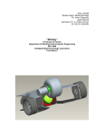
SAE Data Acquisition (SAEDAQ) Project Final Report By: Caleb Davison, George Kontos, & Phil Jacher Advisor: Professor Steven Gutschlag May 7, 2011 Abstract:
The goals for this project are to implement a data acquisition system for the formula
racecar built by Bradley University’s Society of Automotive Engineers. Sensors will be
installed on the car to collect data for oil temperature, oil pressure, coolant temperature,
RPM, and wheel speed. A microcontroller will convert the data to digital signals and
organize it to be sent out. That data will be displayed on an LCD screen mounted to the
car dashboard and also wirelessly transmitted to an off-track laptop. The LCD and the
laptop will concurrently display the data in real time. The laptop will also have a feature
that will save and store the data for further analysis.
SAEDAQ
2 | Page
Table of Contents:
Introduction................................................................................................................4
High-Level System Block Diagram...........................................................................5
Microcontroller ..........................................................................................................5-6
Aerocomm Wireless Boards ......................................................................................6
Touchscreen Display..................................................................................................7
LabVIEW User Interface ...........................................................................................8-11
Measurement Display ....................................................................................8
Communications ............................................................................................9-10
Data Plotted Versus Time ..............................................................................10
Data Log Feature ...........................................................................................11
Measurement Sensors ................................................................................................11-14
Temperature and Pressure..............................................................................11-13
Wheel Speed ..................................................................................................13
Engine RPM...................................................................................................13-14
Results and Analysis ..................................................................................................14
Appendices
Appendix A – Aerocomm Tutorial ................................................................15-16
Appendix B – LabVIEW Backpanel .............................................................17
Appendix B – Amulet Communications........................................................18-20
Appendix C – Amulet Tutorial ......................................................................21-26
Appendix D – Final Microcontroller Coding ................................................27-36
SAEDAQ
3 | Page
Introduction
Racing and technology have been partnered together for several decades. They have a
mutual relationship in which technology helps the car run faster and more efficiently, and
racing helps expedite the rate of new and better technologies. Any driver will tell you
that just a few seconds shaved off of their race time can mean the difference between
winning and losing a race, and that the process of analyzing data taken from their car in a
practice run can lead to tweaks and improvements on the car’s systems. This could be all
that is needed to give a driver the edge he needs to beat the competition. Nowhere in
professional racing does one see a driver failing to take advantage of as much technology
as they can in order to acquire more data about their cars.
This project has been attempted in past years, but has never been able to develop a fullyintegrated, working system where the next step would be to combine it with the SAE
Formula Car. Although some concepts have been duplicated from previous years, the
majority of the hardware and software decisions have been of our own design in order to
achieve the goals we had set for our project.
SAEDAQ
4 | Page
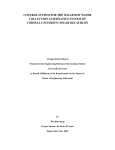
High-Level System Block Diagram
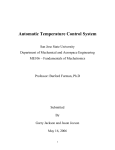
Figure 5-1 shows a high-level system block diagram of our system. Analog and digital
sensors send data acquired from the formula car to the microcontroller. The
microcontroller’s software processes and formats both the analog and digital data to be
sent via RS-232 to the Amulet display for on-car viewing, as well as the Aerocomm
wireless boards. The touchscreen displays the real-time data with appropriate warning
screens to tell the user if any of the values go out of their designated safety range. A
second wireless board receives the data sent by the microcontroller where it is logged and
viewed in real-time via a laptop equipped with LabVIEW.
Figure 5-1 High-Level System Block Diagram
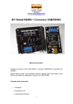
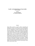
Microcontroller
Written using C code, the Mavric-IIB development board (Figure 6-1) uses the Atmel
Atmega128 microcontroller and processes the analog and digital sensors located on the
car. The oil temperature, oil pressure, and coolant temperature are measured with the
microcontroller’s A/D converter. These values are scaled into a single byte value with a
reference voltage range of 0-2.56 VDC. The RPM and wheel speed (MPH) are measured
counting TTL pulses coming from the sensors. The values are sent to the Aerocomm
wireless board and the LCD touch screen for transmission and display. Below are the
performance specifications:
• A timer on the microcontroller counts the pulses from both the rpm and mph
sensors. The TTL pulses are sampled every 100 ms.
• The microcontroller uses the A/D converter on the Mavric-IIB to sample the
coolant temperature, oil temperature, and oil pressure. The total sampling time for
the three values being recorded is 312 µs.
• The microcontroller sends the real-time data to both the LCD and wireless
antenna every 500ms.
The final coding for the microcontroller can be seen in Appendix A. The documentation
on the programming progress is shown in Appendix B.
SAEDAQ
5 | Page
Figure 6-‐1 Mavric-‐IIb Microcontroller Board
Aerocomm Wireless Boards
The project started with the Chipcon CC12500 DK development board using the TI
CC2400 wireless transceivers (Figure 6-1). However, after much time attempting to set
up and interface the wireless, there was not enough documentation on how to set up these
antennas. The TI tech support was not helpful in getting it to function properly, and only
suggested to buy their newer version of the antenna. After much research and
troubleshooting, we decided to move to another antenna. We switched to the Aerocomm
AC-4790 transceivers (Figure 6-2). These chips were much easier to set up and only took
about one full lab day’s worth of research to get them to function properly. The
Aerocomm chip transmits at 9600 baud on a 900 MHz chipset. The values are received in
a 12-byte data packet that is transmitted every 500 ms. The data received from the
antenna is attached to a laptop where LabVIEW parses and uses the date for live-view
analysis.
Figure 6-1 Chipcon CC2400
SAEDAQ
Figure 6-2 Aerocomm AC-4790
6 | Page
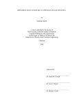
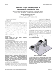
Touchscreen Display
The touchscreen display was an essential part of the system because it gives the driver
data in real time. This is essential for the integrity of the car and the driver, in that the
driver will be able to monitor the vitals of the car. If a problem with one of the systems
does arise, the driver will be aware of it and will be able to take appropriate actions, such
as pulling over or making other minor adjustments.
The touchscreen used for this project was the Amulet STK-480272C LCD touchscreen.
It is made by Amulet Technologies and came as a packaged deal with GEMstudio, which
is a drag-and-drop GUI design tool. GEMstudio is a powerful tool that allows for a wide
variety of control and object widgets to be designed and implemented into a project. It is
based off of HTML called µHTML, which uses less memory and allows for easy GUI
programming.
The goal of the design for the touchscreen was to make the data, as well as when the
warnings popped up, as visible as possible. Previous projects might not have made this
as efficient as possible, with lower quality screens and designs or scales and gauges that
are too small for the driver to easily see what is going on. Knowing that the driver will
not have his eyes glued to the touchscreen and that there will be plenty of distractions on
the race course at any given time, we chose numeric fields to display the data in the
largest, most visible font that could be made. Figure 7-1 shows the two states that the
touchscreen can be in. The first is when there are no warnings, and the second for when
there is a warning due to a sensor going out of spec. The contrast between the light blue
and red background, as well as the inverted colors of the numeric field that goes out of
spec, are implemented to attempt to catch the driver’s attention, should they not be
looking at the screen at that time.
Figure 7-1 Final Touchscreen Design
The communications between the touchscreen and the microcontroller were not hard to
work out because we were able to directly put the data from the microcontroller into the
internal RAM of the touchscreen via RS-232. The numeric fields, which are coded to
take data from specific addresses in the internal RAM, then display the data. See
Appendix D for specifics about the coding process.
SAEDAQ
7 | Page
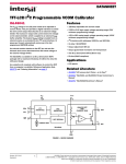
LabVIEW User Interface
LabVIEW is a graphical programming language used industry-wide for data acquisition
and processing, control systems, and system monitoring. In this project, LabVIEW
provides a graphical user interface for an off-track team to monitor the performance of
the car. Along with displaying the data in real-time, the LabVIEW program plots the
data versus time and logs the data to an Excel file specified by the user. Figure 8-1
shows the user interface.
Figure 8-1 LabVIEW User Interface
Measurement Display
The same measurements that are seen by the driver in the Formula One car are seen by an
off-track team. The data is updated in real-time once it is wirelessly transmitted. Figure
8-2 shows the front panel of the user interface.
Figure 8-2 LabVIEW Front Panel
SAEDAQ
8 | Page
Communications
The LabVIEW user interface receives data being sent to it via RS232 communication.
The front panel allows the user to change the communication settings: port number, baud
rate, data bits, flow, stop and parity bits. For this specific project, we used the following
settings:
• Baud Rate: 9600 • Data Bits: 8 • Flow Control: None • Stop Bits: 1 • Parity: 0 Figure 9-1 shows the communication control portion of the user interface in Figure 8-1.
Figure 9-1 Communication Controls
The data being sent to the PC is handled with the Instrument I/O Assistant. The I/O
Assistant receives the data in packets and parses through it to pull out specific variables
to display. Figure 9-2 shows the I/O Assistant programmed in the Back Panel of the
LabVIEW interface. Figure 9-3 shows the settings window for parsing through data in
the I/O Assistant.
Figure 9-2 I/O Assistant Program
SAEDAQ
9 | Page
Figure 9-3 I/O Assistant Parse Settings
Data Plotted Versus Time
The right portion of our user interface displays the data acquired for wheel speed, engine
RPM, oil pressure, oil temperature and coolant temperature over the time of a race. The
unique feature of these displays is that the user can change the sampling time intervals.
For example, the speed data can be updated every second while the pressure data can be
updated every minute.
This feature is able to be implemented because of LabVIEW ‘parallel computing’
programming structure. While traditional programming languages such as C execute
lines of code sequentially, LabVIEW uses structures, similar to functions and loops,
which execute independent of each other. Figure 10-1 shows an example of this in the
Back Panel programming. The structures are two separate “while loops” with “wait for
(ms)” functions block.
Figure 10-1 Back Panel programming of the data versus time displays
SAEDAQ
10 | Page
Data Log Feature
The final feature of the LabVIEW interface is that the data being sent to it can be logged
into an Excel spreadsheet file. The save feature is the same as any other Windows
application, where the user can specify the file name and directory it is to be saved in.
The file already comes with headers for the columns of data. Once the data log button is
pressed, the LabVIEW program terminates.
Measurement Sensors
The sensors purchased for this project were only modeled for measurement methods, not
implemented.
Temperature and Pressure
The two temperature sensors (TTD25N-20) shown in Figure 11-1 are for oil and coolant
temperature with the following specifications:
• RTD (resistive thermo device) – outputs a proportional response
• 4-20mA output proportional to temperature
• 10-36V operating voltage – can be powered from car battery, minimal power
consumption
• 1/4” MNPT – sensor can thread straight into lines
• 4.5” long ideal size
• Handles 20g’s of vibration, 50g’s of shock
The pressure sensor (PTD25-20) shown in Figure 11-1 has following specifications:
• RTD (resistive thermo device) – outputs a proportional response
• 4-20mA output proportional to temperature
• 9.6 to 32 VDC Operating Voltage
• 1/4” MNPT – sensor can thread straight into lines
• About 3" long
• Handles 20g’s of vibration, 50g’s of shock
Figure 11-1 Temperature and Pressure Sensors
SAEDAQ
11 | Page
In modeling the sensor output, the max resistive load had to be calculated. Equation 1 is
from the sensor data sheet.
RLmax = (Vsupply-9.6)*50
[1]
For this model, Vsupply=12[V] because that is the voltage of the car battery,
corresponding to a 120 ohm resistive load. The sensors are modeled as current sources in
Figure 12-1, our sensor measurement circuit.
Figure 12-1 – Sensor Measurement Circuit
The A/D resolution on the microcontroller was set to 0-2.56[V] since at the sensor output
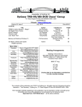
of 20mA, the voltage across the load would be 2.4[V]. Table 12-1 shows the temperature
data corresponding to the A/D value.
A/D Res (2.56/255)
Sensor
Volts
Output (mA)
0.48
4.00
0.49
4.08
0.5
4.17
0.51
4.25
0.52
4.33
0.53
4.42
0.54
4.50
2.34
2.35
2.36
2.37
2.38
2.39
2.4
uC Bit
Number
48
49
50
51
52
53
54
Temperature
(Fahrenheit)
0.00
1.56
3.13
4.69
6.25
7.81
9.38
19.50
234
19.58
235
19.67
236
19.75
237
19.83
238
19.92
239
20.00
240
Table 12-1 – A/D Temperature Data
290.63
292.19
293.75
295.31
296.88
298.44
300.00
Curve fitting analysis was used to find a software calculation for uC bit number to
temperature. However, the formula that was generated contained decimal point
SAEDAQ
12 | Page
arithmetic, which would be inefficient. The solution was to use a software lookup table
because there was enough memory.
The curve-fitting plot is shown in Figure 13-1.
Figure 13-1 – Temperature vs. A/D value curve
Note: The pressure sensor modeling was conducted in the same manner with similar
results. A software lookup table was used as well.
Wheel Speed
The wheel speed sensor (MT-190) was not implemented into the project because we did
not have a proper set up for it. However, the MT-190 was purchased because it is a HallEffect sensor, which eliminates the problem of dirt and grime interfering with the signal
as with a laser tachometer. Hall-Effect sensors have a magnet attached to the end of it,
which outputs a signal when a metal is passed by it. This piece of metal could be a bolt
attached to the wheel. The MT-190W has the following specifications:
• Operating Distance: 0.25” max gap
• Speed Range: 1-99,999 RPM
• Power Required: 5VDC
• Output Signal: TTL 0-5 VDC
• 8 foot cable, 2” long Engine RPM The sensor purchased to measure engine RPM was the ACI Hall-‐Effect current sensor pictured in Figure 14-‐1. The goal was to run the engine ignition coil through the sensor to sense when the coil fires. These pulses could be counted and sampled over a certain time interval to measure engine RPM. This was not implemented because we could not get an ignition coil for testing. SAEDAQ
13 | Page
Figure 14-‐1 – ACI Hall-‐Effect Sensor The ACI sensor has the following specifications: • Sensor Power – induced from monitored conductor • Output – 0-‐5[VDC] • Amperage Ranges – 0-‐250 Amps • Operating Frequency – 50-‐600 Hz Results and Analysis Project milestones were assigned as follows: • George: LabVIEW user interface, sensor measurements • Phil: Touchscreen LCD programming, wireless chips • Caleb: Microcontroller programming/interfacing, wireless chips Each of us worked separately on our respected milestones. Once completed, each milestone was added to the overall project to work together. The microcontroller successfully recorded simulated pressure, temperature and speed readings at a specific rate, and sent those readings to the LCD where it was properly displayed. The same readings were successfully transmitted wirelessly to a PC with the LabVIEW user interface installed. LabVIEW updated in real time as well as logged the data to an Excel file specified by the user. The overall goal of our project was achieved by being able to take car measurements and by sending those measurements to separate user interfaces for displaying and logging without data loss or mismatched values. SAEDAQ
14 | Page
Appendix A: Aerocomm Tutorial
The initial setup of the Aerocomm chips was very easy to do. The Aerocomm kit comes
with two development boards for programming and initializing the AC-4790 transceivers.
To program the transceivers, press the reset button on the development board while it is
still powered. This sets the transceiver to factory default settings so the user can know
what baud rate the transceiver is set at.
1. Power on development board
2. Make sure that the AC-4790 is plugged into the board
3. Press the “reset” button on the development to make sure the antenna is at factory
default settings
4. Make sure that the development board’s header cables are all set on the correct
values. (TTL Radio, USB Enable, +3.3V Radio, Normal Evaluation) Select the
correct power source. The most efficient setting is to use the external power
source. The USB can still be plugged in without any problems with this setting.
5. Open AerocommOEM.exe
6. Select the “PC Settings” tab (this menu shown in Figure 16-2)
a. Click the “Find Ports” button and select the according COM port that the
USB is connected to. Set the baud rate to 57600, parity to “None,”
Handshaking to “None,” data bits to “8,” and stop bits to “1.”
b. Make sure that all of the checkboxes in the options tab are checked
c. Select the appropriate product (AC4790)
7. Click on the configure tab (this menu shown in Figure 16-1)
a. For loading the provided EEPROM file, proceed to part e. For fresh
programming, proceed to the next part.
b. Click on the “Read Radio” button at bottom right of the program. The
EEPROM file should load into the Radio Interface and Radio RF boxes.
c. Change the Interface Baud to 9600 (or whatever baud rate you are using)
d. Set the RF packet size (ours transmission was 12 bytes so we used 0x0C)
Proceed to part f.
e. Click on the “Load File” button and select the location of the file.
f. Click on the “Write Radio” button. If it programs correctly, a message
should tell the user that it programmed correctly.
8. The transceivers are now set up to transmit data packet to each other.
9. In order to re-read or correct programming on the newly programmed chips, the
baud rate under “PC Settings” must be changed to the baud rate that was
programmed to the chip’s EEPROM file. If you cannot fully read the antenna’s
EEPROM after programming, repeat steps 3-8.
10. The “Range Test” tab of the program lets you test null data packets to make sure
that your settings are valid.
11. To transmit the data packets through RS-232, simply move the “USB Enable”
header to the “RS232 Enable” header. Once this is changed, the user should be
able to send their own data packets between boards. This can be tested by
hooking up the boards to two separate computers and typing a message through
hyper terminal.
SAEDAQ
15 | Page
Figure 16-1 Configure Settings
Figure 16-2 PC Settings
SAEDAQ
16 | Page
Appendix B: LabVIEW Backpanel
Figure 17-1 LabVIEW Backpanel
SAEDAQ
17 | Page
Appendix C: Amulet Communications
Amulet Communications Tutorial
In order to communicate with the Amulet screen, the RS-232 communication needs to be
understood. There are two ways to communicate with the Amulet: ASCII and CRC. For
our application, we chose the CRC protocol using XON/XOFF. Unlike the CRC protocol,
this protocol was simple and did not require multi-byte handshaking. In order to work in
this function, the Amulet must be set to slave no response mode. In this setting, the
Amulet only receives the byte packet commands, but does not send any information
packets back to its sender. In the XON/XOFF protocol, the microcontroller sends its full
packet of commands. It ends each transmission with the XOFF command (0x13). The
Amulet interprets data in the order that it was received. When it reaches the last value in
the data packet (XOFF command), it sends the XON command to the microcontroller
which tells the microcontroller that the receive buffer is empty and ready for receiving
again. This description is shown in Figure 18-1. If the XON/XOFF procedure was not
used, the Amulet could possibly result in a loss of data since the receive buffer is not
cyclic.
Figure 18-1 Amulet Data Packet Transmission using XON/XOFF
Now that the concept of sending data has been explained, example coding of specific
Amulet CRC protocol commands will be shown. Figure 19-1 shows how to send a
command for saving to the internal RAM of the Amulet. Saving a CRC value to internal
RAM involves three parts: Opcode, internal RAM address, and the internal RAM value.
The Opcode is the single-byte command telling the Amulet what bytes are going to be
coming next and what to do with them. In Figure 19-1, the 0xD5 Opcode is telling the
Amulet to program the byte received to the internal RAM. The figure depicts what each
byte value is by color coordination. For further analysis, the CRC commands that were
not used on our project can be found on Amulet’s tutorial website under the “UART CRC
Protocol” section.
http://www.amulettechnologies.com/GEMhelp/GEMcompiler/Help.htm.
SAEDAQ
18 | Page
Save byte value 0xFE to internal RAM address 0x01
Save word value 0x02C9 to internal RAM address 0x00
Opcode
Internal RAM address
Internal RAM value
Figure 19-1 Sending Values to Internal RAM
Unlike the CRC commands shown in Figure 19-1, the jump to screen function does not
follow the normal CRC protocol. Each Amulet page has its own two byte identifier
address which is used for the jump to page function. Unlike the CRC protocol, the
Opcode is two bytes long. The jump to page function first sends the two byte command,
the page address starting with the most significant byte, then the checksum. The
checksum is an algorithmic value that is used to make sure that the bytes before it were
actual valid data. The calculation of the checksum is explained below. The jump to page
example is shown in Figure 19-2.
Save byte value 0xFE to internal RAM address 0x01
Opcode
Internal RAM address
Internal RAM value
Figure 19-2 Sending Jump to Page Function
To calculate the checksum, the first four bytes must be added together.
The sum of “X” and the checksum values must make the least significant byte equal
0x00. Therefore,
Check to prove that the value for the checksum is correct:
The checksum is correct since the MSB is equal to zero.
SAEDAQ
19 | Page
The string from the final microcontroller coding is shown in Figure 20-1 to help visualize
the multiple bytes that are being sent to the Amulet in one single data packet
transmission. Bytes 0-1, words 0-2, and bytes 5-9 are all saved to their assigned internal
RAM locations. Bytes 5-9 are the warning bytes to tell the Amulet to invert the colors on
the display. The jump to screen command is then sent, which tells the display to be on
either the normal screen or the red warning screen. The last byte sent is the XOFF
command.
volatile unsigned char transmit[] = {
213,'0','0','0','0',//byte(0) - coolant temp
213,'0','1','0','0',//byte(1) - pressure
214,'0','0','0','0','0','0',//word(0) - oil temp
214,'0','1','0','0','0','0',//word(1) - wheel speed
214,'0','2','0','0','0','0',//word(2) - engine speed
213,'0','5','0','0',//byte(5) - coolant temp warning flag
213,'0','6','0','0',//byte(6) - oil pressure warning flag
213,'0','7','0','0',//byte(7) - oil temp warning flag
213,'0','8','0','0',//byte(8) - wheel speed warning flag
213,'0','9','0','0',//byte(9) - engine speed warning flag
160,2,0,32,62,//jump to screen
19};//send XOFF for end of transmission
Figure 20-1 Amulet String Packet
An ASCII table has been provided to help users convert what the values are in software
coding. This ASCII table is shown in Figure 20-2.
Figure 20-2 ASCII Table
SAEDAQ
20 | Page
Appendix D: Amulet Tutorial
You can find all the information below and more at Amulet’s website at
www.amulettechnologies.com. From there, a video can be watched that gives a very
basic, but somewhat helpful example at www.amulettechnologies.com/videos.html
Clicking the Help Documentation link off the main page brings you to a webpage with
several useful links. Most important is the USER’S GUIDE(GEMstudio) link and the
PROGRAMMER’S GUIDE(GEMcompiler) link. The former link is where the bulk of
the information needed to understand GEMstudio is.
When you open GEMstudio, clicking the first menu button will open the project
configuration. Make sure that the LCD size is 480x272, which is the size of the
touchscreen we have currently.
In the Communications tab, you can set the protocol type to ASCII or CRC. For more
information on the differences between the two protocols, see the user’s guide
(GEMstudio) link. The protocols for ASCII and CRC are on the left side. The
documentation given in the link was very helpful for understanding how these protocols
work from both the touchscreen and the microcontroller’s point of view.
A couple of notes about the sections that describe the widgets:
-The font and font size can exceed the presets that the studio gives. Instructions
can be found below how to modify this.
-The example “code” the guide gives where it starts each line with <PARAM
NAME= …> doesn’t have to be coded. It is all part of GEMstudio’s GUI and can
be managed with the menus and not the code.
The only coding you are probably going to do when making a project is coding in the
href parameter, which links the control widgets with the object widgets, and in the
META-refresh, which can call functions for a specific page of your touchscreen.
For the href commands, the general syntax is Amulet:document.widgetname.method().
-Widgetname is the user defined name for the called widget. The default name
for a widget is MyWidgetName. For example, the default name for a function
button would be MyFuncButton. Double click the MyFuncButton to change it to
whatever you want.
-The options for what the method() function can be is in Appendix B of the user’s
guide, which I have attached at the end of this document.
If you wanted to make a static image disappear on a button press and the image’s name
was “image,” the code you would put in the function button’s href would be:
SAEDAQ
21 | Page
Amulet:document.image.disappear()
To add multiple commands to one widget, separate with a comma.
….disapear(), Amulet:document……
Logic functions, functions called based on timer events, if/then/else statements, and
initializing internal RAM variables that are tied to the page and not a specific widget are
to be put in the META-refresh. The META-refresh is found in ‘page functions’ under the
project tab in GEMstudio.
In my design, I wanted a “if” statement that would check for a specific byte to be set, and
when that byte is set, invert the colors of a corresponding widget. The byte would be set
by the microcontroller, which would send it over RS-232 when the situation called for the
byte being set. The code in the META-refresh is:
<META HTTP-EQUIV="REFRESH"
CONTENT="0.01;
IF=Amulet:InternalRAM.byte(7).value();
EQ=1;
THEN=Amulet:document.OilTemp.inverseRegionColor();
NAME=invoiltemp">
The code above says that, every .01 seconds, check if byte 7 in the internal RAM equals
1. If it is 1, invert the background color of the numeric field displaying oil temperature.
The general syntax is as follows:
<META HTTP-EQUIV="REFRESH"
CONTENT="updateRate, delayRate;
IF=function;
{EQ | GT | LT | NEQ}=value; (equals | greater than | less than | does not equal)
THEN=function(s);
ELSE=function(s);
NAME=string">
One of the earlier widgets that I played around with was the radio button; the GEMstudio
user’s manual gives the definition:
A Radio Button is a labeled, round button used to make a single selection from several
options. To set a radio button, click on either the button or the adjacent label. All radio
buttons that have the same groupName are considered part of a radio button group. Only
one radio button within a group can be set at any one time. When a radio button is
selected, its function(s) are called with the argument being the intrinsic value of the radio
button. Each radio button can invoke its own href function (or set of functions).
The radio button can be set up with other radio buttons, so only one can be pressed at a
time. Right clicking either the widget or its name in the drop down menu on the left
SAEDAQ
22 | Page
opens a dropdown menu. Click add/remove parameters to open the menu. Checking and
unchecking the boxes will add/remove properties on that individual widget’s menu.
For example, say you want a radio button to be a red button when not pressed, grayed out
when being pressed, and then green after it is pressed. You would go into the widget’s
menu and make sure emptyImage, trackingImage, and fullImage were checked. The next
step would be to then click the plus box next to the individual parameters, and add the
.JPG to the respected parameter. Note that if you use an image with a .JPEG extension,
the compiler will generate an error. You need to use an image with .JPG.
Amulet:document.widgetName.buttonDown()
The named Function/Custom Button Widget will
appear as if it is currently being touched.
Amulet:document.widgetName.buttonUp()
The named Function/Custom Button Widget will
appear as if it is currently NOT being touched.
Amulet:document.widgetName.clearCanvas()
The named Scribble/Dynamic Image Widget clears
its canvas, including any background images.
Amulet:document.widgetName.disappear()
The named widget will clear itself from the LCD; if
it is a View Widget it will also stop updating.
Amulet:document.widgetName.forceHit()
The named Control Widget will act as if it was
"hit".
Amulet:document.widgetName.forceRefresh()
The named View Image Sequence Widget will paint
the image at the next update, even if the incoming
value is the same as the current state. Useful if an
anchor is used around an Image Sequence Widget.
Amulet:document.widgetName.forceUpdate()
The named View Widget will act as if it's update
rate time was activated. Allows for asynchronous
updating.
Amulet:document.widgetName.inverseRegionColor(
The named widget will display in reverse video.
)
Amulet:document.widgetName.inverseStringColor()
The named widget's text string will display in
reverse video.
Amulet:document.widgetName.nextEntry()
The named List widget will move its highlighted bar
down to the next entry. Does not perform a "hit" on
the new entry.
Amulet:document.widgetName.normalRegionColor(
The named widget will display in normal video.
)
Amulet:document.widgetName.normalStringColor()
The named widget's text string will display in
normal video.
Amulet:document.widgetName.previousEntry()
The named List widget will move its highlighted bar
up to the previous entry. Does not perform a "hit"
on the new entry.
SAEDAQ
23 | Page
Amulet:document.widgetName.reappear()
The named widget will reappear on the LCD in its
original location; if it is a View Widget it will also
start updating.
Amulet:document.widgetName.reset()
The named widget will initialize internal variables
and re-draw.
Amulet:document.widgetName.setMethod(m)2
The href method for the named widget will change
to m, where m is the method name. (such as value()
or disappear())
Amulet:document.widgetName.setOnVarMethod(m)
2
The IF= method for the named widget will change
to m, where m is the method name. (such as value()
or disappear())
The ONVAR UART method for the named widget
Amulet:document.widgetName.setOnVarUARTMet
will change to m, where m is the method name.
hod(m)2
(such as Value())
The variable number used in the ONVAR of the
Amulet:document.widgetName.setOnVarVariableNu named widget will change to x, where x is the
mber(x)1
variable index used in the following variable types:
byte(x), word(x) or string(x).
Amulet:document.widgetName.setTrigger(x)1
The named Widget will change its equal, gt or lt
value to the byte value x.
2
The href UART method for the named widget will
change to m, where m is the UART:method name.
(such as Value())
Amulet:document.widgetName.setUpdateRate(f)3
The update rate for the named widget will change to
f, where f is a floating point number that represents
the update rate in seconds.
Amulet:document.widgetName.setValue(x)1
The named widget will receive the intrinsic value of
the calling widget, where x is the intrinsic value.
Amulet:document.widgetName.setUARTMethod(m)
The variable number used in the href of the named
Amulet:document.widgetName.setVariableNumber(x widget will change to x, where x is the variable
)1
index used in the following variable types: byte(x),
word(x) or string(x).
Amulet:document.widgetName.setX4(x)
The named Widget will change its topleft x
coordinate to the word value x.
Amulet:document.widgetName.setY4(x)
The named Widget will change its topleft
y coordinate to the word value x.
Amulet:document.widgetName.startUpdating()
The named View Widget will start updating the
displayed data.
Amulet:document.widgetName.stopUpdating()
The named View Widget will stop updating the
displayed data.
Amulet:document.widgetName.toggleRegionColor() The named widget will either start or stop
SAEDAQ
24 | Page
displaying in reverse video.
Amulet:document.widgetName.toggleStringColor()
The named widget's text string will either start or
stop displaying in reverse video.
Amulet:document.widgetName.toggleUpdating()
The named View Widget will either start or stop
updating the displayed data.
1. Regarding x: For Control Widgets that have intrinsic values, such as lists and sliders, leave the
argument field empty, since the intrinsic value of the selection will be sent out. META REFRESH tags and
Function/Custom Buttons should use x. The range for x is 0-255 (0x00-0xff) for a BYTE, 0-65535 (0x000xffff) for a WORD and 250-character strings in double quotes for STRINGs.
2. Regardingm - When setMethod(),setOnVarMethod(),setOnVarUARTMethod() or setUARTMethod(),
is the IWC method, the argument should be the name of the method you want to set. i.e. disappear() or
byte.value(). Notice when dealing with a method that relies on a type (byte, word or string) you need to
include the type separated by a dot and then the method (i.e. word.value()) instead of just the method by
itself.
3. Regarding f: For Control Widgets that have intrinsic values, such as lists and sliders, leave the argument
field empty, since the intrinsic value of the selection will be sent out. META REFRESH tags and
Function/Custom Buttons should use f. Like the regular updateRate, use a floating point number to specify
the update rate in seconds. Range for f is 0-655.35
4. Regarding setX and setY: These methods should most always be preceded by a disappear() method and
followed by a reappear() method. The setting of the x and y coordinates are independent of the removal of
the widget in the old coordinates and the displaying in the new coordinates.
Below is the code used in the page 2 (the red screen) META-refresh which can be found by clicking on the
‘Page Function” tab.
<META HTTP-EQUIV="REFRESH"
CONTENT="0.01;
IF=Amulet:InternalRAM.byte(7).value();
EQ=1;
THEN=Amulet:document.OilTemp.inverseRegionColor();
NAME=invoiltemp">
<META HTTP-EQUIV="REFRESH"
CONTENT="0.01;
IF=Amulet:InternalRAM.byte(6).value();
EQ=1;
THEN=Amulet:document.OilPress.inverseRegionColor();
NAME=invOilPress">
<META HTTP-EQUIV="REFRESH"
CONTENT="0.01;
IF=Amulet:InternalRAM.byte(5).value();
EQ=1;
THEN=Amulet:document.Coolant.inverseRegionColor();
NAME=invCoolant">
<META HTTP-EQUIV="REFRESH"
SAEDAQ
25 | Page
CONTENT="0.01;
IF=Amulet:InternalRAM.byte(8).value();
EQ=1;
THEN=Amulet:document.MPH.inverseRegionColor();
NAME=invmph">
<META HTTP-EQUIV="REFRESH"
CONTENT="0.01;
IF=Amulet:InternalRAM.byte(9).value();
EQ=1;
THEN=Amulet:document.RPM.inverseRegionColor();
NAME=invrpm">
SAEDAQ
26 | Page
Appendix E: Final Microcontroller Coding
NOTE: the final coding is also available on the final project CD to make viewing easier
/* Caleb Davison
* Created 03/29/11
* LabVIEW and touchscreen interfacing
*
* This program takes three different voltages from the ADC
* It also counts the pulses in a set time frame
* The values are outputted to the Amulet screen and LabVIEW
*/
#include <avr/io.h>
#include <inttypes.h>
#include <avr/interrupt.h>
//function header declarations
int to_ascii (int val);
//LCD screen variables
volatile unsigned int arr_size = 0;
volatile unsigned char ready = 1;
volatile unsigned char i = 0;
//max warning values
volatile unsigned char
volatile unsigned char
volatile unsigned int
volatile unsigned int
volatile unsigned int
coolant_max = 200;
pressure_max = 200;
oil_temp_max = 200;
mph_max = 190;
max_rpm = 12000;
volatile unsigned int pc_time = 0;
volatile unsigned char j = 0;
volatile unsigned int arr_size_1 = 0;
//transmit buffer string
volatile unsigned char transmit[] = {213,'0','0','0','0',//byte(0) coolant temp
213,'0','1','0','0',//byte(1) - pressure
214,'0','0','0','0','0','0',//word(0) - oil temp
214,'0','1','0','0','0','0',//word(1) - wheel speed
214,'0','2','0','0','0','0',//word(2) - engine speed
213,'0','5','0','0',//byte(5) - coolant temp warning flag
213,'0','6','0','0',//byte(6) - oil pressure warning flag
SAEDAQ
27 | Page
213,'0','7','0','0',//byte(7) - oil temp warning flag
213,'0','8','0','0',//byte(8) - wheel speed warning flag
213,'0','9','0','0',//byte(9) - engine speed warning flag
160,2,0,32,62,//jump to screen
19};//send XOFF for end of transmission
//LabVIEW String
volatile unsigned char daq_data[] = {'0','0',
'0','0',
'0','0','0','0',
'0','0','0','0',
'0','0','0','0',
10};
//time to updat the display (in increments of the timer interrupt
value)
volatile unsigned int display_time = 0;
//declare ADC storage value
volatile unsigned char sensor = 0;
//Coolant Temp Values
volatile unsigned char coolant_temp = 0;
volatile unsigned char cool_1 = '0';
volatile unsigned char cool_0 = '0';
//Oil Pressure Values
volatile unsigned char pressure = 0;
volatile unsigned char pressure_1 = '0';
volatile unsigned char pressure_0 = '0';
//Oil Temp Values
volatile unsigned
volatile unsigned
volatile unsigned
volatile unsigned
volatile unsigned
int
char
char
char
char
//MPH Values
volatile unsigned
volatile unsigned
volatile unsigned
volatile unsigned
volatile unsigned
int mph = 0;
char mph_11 =
char mph_10 =
char mph_01 =
char mph_00 =
'0';
'0';
'0';
'0';
//RPM Values
volatile unsigned
volatile unsigned
volatile unsigned
volatile unsigned
volatile unsigned
int rpm = 0;
char rpm_11 =
char rpm_10 =
char rpm_01 =
char rpm_00 =
'0';
'0';
'0';
'0';
SAEDAQ
oil_temp = 0;
oil_temp_11 =
oil_temp_10 =
oil_temp_01 =
oil_temp_00 =
'0';
'0';
'0';
'0';
28 | Page
//external interrupt count value for rpm
volatile unsigned char count = 1;
volatile unsigned char update = 1;
ISR(USART0_UDRE_vect){//interrupt for when the UDR0 transmit buffer is
empty
if(j == arr_size_1){
//UCSR0B &= 247;//stop transmitter
UCSR0B &= 223;//stop UDR0 interrupt
}else if(j!=arr_size_1){
UDR0 = daq_data[j];
j++;
}
}
//External Interrupt 1 - PORTD1
ISR(INT1_vect) {
count = count + 1;
}
ISR(TIMER1_COMPA_vect) {//interrupt for timing
display_time = display_time + 1;
pc_time = pc_time +1;
//record mph into 8-bit counter
mph = TCNT2;
TCNT2 = 0;
//record engine rpm
rpm = count;
//ADD RPM CONVERSION FORMULA HERE!!!
rpm = rpm*48;
//END OF CONVERSION FORMULA
//set counter back to zero
count = 0;
//convert mph to display on screen
mph_11 = to_ascii((mph >> 12) & 0x0F);
mph_10 = to_ascii((mph >> 8) & 0x0F);
mph_01 = to_ascii((mph >> 4) & 0x0F);
mph_00 = to_ascii(mph & 0x0F);
//convert rpm to display on screen
rpm_11 = to_ascii((rpm >> 12) & 0x0F);
rpm_10 = to_ascii((rpm >> 8) & 0x0F);
rpm_01 = to_ascii((rpm >> 4) & 0x0F);
rpm_00 = to_ascii(rpm & 0x0F);
SAEDAQ
29 | Page
//
if(pc_time==5){//allow transmission after one second
mode = 'a';
j = 0;
pc_time = 0;
//UCSR0B |= _BV(TXEN0);//enable transmitter
//update = 1;
//coolant temp
daq_data[0]=cool_1;
daq_data[1]=cool_0;
//oil pressure
daq_data[2]=pressure_1;
daq_data[3]=pressure_0;
//oil temp
daq_data[4]=oil_temp_11;
daq_data[5]=oil_temp_10;
daq_data[6]=oil_temp_01;
daq_data[7]=oil_temp_00;
//wheel speed
daq_data[8]=mph_11;
daq_data[9]=mph_10;
daq_data[10]=mph_01;
daq_data[11]=mph_00;
//RPM
daq_data[12]=rpm_11;
daq_data[13]=rpm_10;
daq_data[14]=rpm_01;
daq_data[15]=rpm_00;
//reenable UDRIE0 interrupt
UCSR0B |= _BV(UDRIE0);
}
if(ready==1){
if(display_time==5){
display_time = 0;
i=0;//start up transmission array position counter
//byte 0 - coolant temp
transmit[3]=cool_1;
transmit[4]=cool_0;
//byte 1 - oil pressure
transmit[8]=pressure_1;
transmit[9]=pressure_0;
//word 0 - oil temp
transmit[13]=oil_temp_11;
transmit[14]=oil_temp_10;
transmit[15]=oil_temp_01;
transmit[16]=oil_temp_00;
SAEDAQ
30 | Page
//word 1 - wheel speed
transmit[20]=mph_11;
transmit[21]=mph_10;
transmit[22]=mph_01;
transmit[23]=mph_00;
//word 2 - RPM
/*
transmit[27]=mph_11;
transmit[28]=mph_10;
transmit[29]=mph_01;
transmit[30]=mph_00;
*/
transmit[27]=rpm_11;
transmit[28]=rpm_10;
transmit[29]=rpm_01;
transmit[30]=rpm_00;
if(coolant_temp>coolant_max){ //jump to warning
screen
//byte 5
transmit[34]='0';
transmit[35]='1';
}else{
//stay on default
screen
//byte 5
transmit[34]='0';
transmit[35]='0';
}
if(pressure>pressure_max){
transmit[39]='0';
transmit[40]='1';
}else{
transmit[39]='0';
transmit[40]='0';
}
if(oil_temp>oil_temp_max){
transmit[44]='0';
transmit[45]='1';
}else{
transmit[44]='0';
transmit[45]='0';
}
if(mph>mph_max){
transmit[49]='0';
transmit[50]='1';
}else{
transmit[49]='0';
transmit[50]='0';
}
if(rpm>max_rpm){
transmit[54]='0';
transmit[55]='1';
}else{
transmit[54]='0';
transmit[55]='0';
SAEDAQ
31 | Page
}
if(coolant_temp>coolant_max || pressure>pressure_max
|| oil_temp>oil_temp_max || mph>mph_max || rpm>max_rpm){
//jump to warning screen
transmit[59]=36;
transmit[60]=58;
}else{
//jump to default screen
transmit[59]=32;
transmit[60]=62;
}
UCSR1B |= _BV(TXEN);//enable transmitter
}
}
}
//ADC conversion complete interrupt flag
ISR(ADC_vect) {
if(sensor==0){
sensor = 1;
//grabs the current value
coolant_temp = ADCH;
//convert to the proper ascii transmission values of the
ADC byte value
cool_1 = to_ascii(coolant_temp >> 4);
cool_0 = to_ascii(coolant_temp & 0x0F);
//switch to ADC1
ADMUX &= 0xF0;
ADMUX |= _BV(MUX1);
}else if(sensor==1){
sensor = 2;
//grabs the current value
pressure = ADCH;
//convert to the proper ascii transmission values of the
ADC byte value
pressure_1 = to_ascii(pressure >> 4);
pressure_0 = to_ascii(pressure & 0x0F);
//switch to ADC2
ADMUX &= 0xF0;
//ADMUX |= _BV(MUX1);
}else if(sensor==2){
sensor = 0;
//grabs the current value
oil_temp = ADCH;
//convert to the proper ascii transmission values of the
ADC byte value
oil_temp_11 = to_ascii((oil_temp >> 12) & 0x0F);
oil_temp_10 = to_ascii((oil_temp >> 8) & 0x0F);
oil_temp_01 = to_ascii((oil_temp >> 4) & 0x0F);
SAEDAQ
32 | Page
oil_temp_00 = to_ascii(oil_temp & 0x0F);
//switch to ADC0
ADMUX &= 0xF0;
ADMUX |= _BV(MUX0);
}
}
//USART1_UDRE_vect
//interrupt for when the UDR0 transmit buffer is empty
ISR(USART1_UDRE_vect){
if(i == arr_size){
UCSR1B &= 247;//stop transmitter
}
UDR1 = transmit[i];
if(i!=arr_size){
i++;
}
}
ISR(USART1_RX_vect){//receiver interrupt
//NOTE: In order to function properly, the UDR byte must always be read
//
from in this interrupt; otherwise, the interrupt will
instantly
//
interrupt again upon exiting
if(UDR1==17){
ready = 1;
}
}
int main(void)
{
DDRC = 0xFF;
DDRF = 0x00;
DDRA = 0xFF;
DDRE = 0xFF;
/* enable PORTE as an output */
/* enable PORTF as an input */
/* enable PORTA as an output */
/*************************** ADC SETUP
****************************************/
//set ref value to Vcc
//left adjust output to use only ADCH
ADMUX = _BV(REFS0) | _BV(ADLAR);
//switch to ADC0
ADMUX &= 0xF0;
//enable AtoD converter
//start conversion
//setup free running mode to contiuously update values
//enable AtoD interrupts
SAEDAQ
33 | Page
//set prescaler to 128
ADCSRA = _BV(ADEN) | _BV(ADSC) | _BV(ADFR) | _BV(ADIE) |
_BV(ADPS2) | _BV(ADPS1) | _BV(ADPS0);
/*************************** Timer 1 SETUP
***********************************/
// sets the compare time to 0.1 sec in hexadecimal value when
using prescaling (1/64)
OCR1A = 0x61A7;
//set this bit to clear the timer on compare match (pg 135)
TCCR1B |= _BV(WGM12);
//sets this bit to enable timer 1 interrupt
TIMSK |= _BV(OCIE1A);
//start timer
//sets the clock to 1/64 prescaling and turns timer on (pg 137)
TCCR1B &= ~_BV(CS12); //makes sure the CS12 bit is cleared
TCCR1B |= _BV(CS11);
TCCR1B |= _BV(CS10);
/*************************** Timer 2 SETUP
***********************************/
//8-bit counter
//sets the clock to use an external clock source using pin T2
//pin T2 is located on PORTD7
TCCR2 |= _BV(CS22);
TCCR2 |= _BV(CS21);
TCCR2 |= _BV(CS20);
/*************************** Timer 3 SETUP
***********************************/
//16-bit counter
//sets the clock to use an external clock source using pin T3
//pin T2 is located on PORTE6
TCCR3A |= _BV(CS32);
TCCR3A |= _BV(CS31);
TCCR3A |= _BV(CS30);
//initialize counter to zero
TCNT3H = 0;
TCNT3L = 0;
/************************** RS-232 UART1 SETUP
*******************************/
//set baud rate to 9600
unsigned int baudrate = 103; //see page 197 for baud rate
settings
UBRR0H = baudrate>>8;
UBRR0L = baudrate;
arr_size_1 = (sizeof(daq_data) / sizeof(daq_data[0]));
//enable the transmitter and receiver
UCSR0B |= _BV(TXEN) /*| _BV(RXEN)*/;
//set frame format: 8-bit
UCSR0C = _BV(UCSZ01) | _BV(UCSZ00);
//enables UDRE0 interrupt
UCSR0B |= _BV(UDRIE0);
SAEDAQ
34 | Page
//enables receiver interrupt
//UCSR0B |= _BV(RXCIE0);
//enables transmitter interrupt
//UCSR0B |= _BV(TXEN0);
/************************** RS-232 UART1 SETUP
*******************************/
//set baud rate to 9600
//unsigned int baudrate = 103; //see page 197 for baud rate
settings
UBRR1H = baudrate>>8;
UBRR1L = baudrate;
//enable the transmitter and receiver
UCSR1B |= _BV(TXEN) | _BV(RXEN);
//set frame format: 8-bit
UCSR1C = _BV(UCSZ11) | _BV(UCSZ10);
//enables UDRE1 interrupt
UCSR1B |= _BV(UDRIE1);
//enables receiver interrupt
UCSR1B |= _BV(RXCIE1);
//enables transmitter interrupt
//UCSR0B |= _BV(TXEN1);
arr_size = (sizeof(transmit) / sizeof(transmit[0]));
/***************************** Ext Int 1
**************************************/
//located at PORTD1
//set external interrupts 1 as rising edge generation
//ICS11 ICS10 ICS01 ICS00
EICRA |= _BV(ISC11) | _BV(ISC10);
//Enable External Interrupt 0 and 1
EIMSK |= _BV(INT1);
/**********************************************************************
********/
//Enables ALL Interrupts
SREG = 0x80;
//endless loop
while(1){
/*
if(update==1){
update = 0;
//coolant temp
transmit[0]=cool_1;
transmit[1]=cool_0;
//oil pressure
transmit[2]=pressure_1;
transmit[3]=pressure_0;
//oil temp
SAEDAQ
35 | Page
transmit[4]=oil_temp_11;
transmit[5]=oil_temp_10;
transmit[6]=oil_temp_01;
transmit[7]=oil_temp_00;
//wheel speed
transmit[8]=mph_11;
transmit[9]=mph_10;
transmit[10]=mph_01;
transmit[11]=mph_00;
//RPM
transmit[12]=rpm_11;
transmit[13]=rpm_10;
transmit[14]=rpm_01;
transmit[15]=rpm_00;
}
*/
}
} /* end main statement */
//TO_ASCII
//this function converts a 4-bit value into its proper hexadecimal
value into ASCII
//in order to be transmitted to the Amulet using ASCII protocol
int to_ascii (int val){
switch(val){
case 0:
val='0';
break;
case 1:
val='1';
break;
case 2:
val='2';
break;
case 3:
val='3';
break;
case 4:
val='4';
break;
case 5:
val='5';
break;
case 6:
val='6';
break;
case 7:
val='7';
break;
case 8:
val='8';
break;
case 9:
SAEDAQ
36 | Page
case
case
case
case
case
case
val='9';
break;
10:
val='A';
break;
11:
val='B';
break;
12:
val='C';
break;
13:
val='D';
break;
14:
val='E';
break;
15:
val='F';
break;
}
return(val);
}
SAEDAQ
37 | Page