1
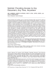
E-sniff: An Embedded Ethernet Packet Sniffer
By Alex Hoyland
Advisors:
Mr. Steven Gutschlag
Dr. Aleksander Malinowski
Abstract
Packet sniffers are devices or programs capable of intercepting and
logging network traffic for which they were not the intended recipient.
Their ability to eavesdrop on network traffic has made them indispensable
tools for IT administrators. In modern IP networks, packet sniffers are
often used to determine the source of network problems, detect intrusions
and locate vulnerabilities. Sniffers can also be used for covert surveillance
of users' internet activities. Packet sniffers are typically implemented as
software programs running on PCs, which is an inefficient implementation
for three reasons. (1) A PC-based packet sniffer is physically large and
difficult to hide, making it less useful for covert eavesdropping. (2)
Sniffing software uses a large amount of processor time, which could be
better utilized by serving data in a corporate network environment. (3) PC
operating systems usually transmit data onto the network, announcing the
presence of the sniffer and making it more prone to detection. This paper
investigates the practicality of building a special-purpose embedded
system capable of intercepting and logging network data in real time. The
proposed system does not transmit any data onto the network, making it
difficult to detect electronically, and will also be small enough to conceal
easily in a person's home or office.
1
Table Of Contents
1. Introduction
3
1.1 The Ethernet Network Topology............................................................... 3
1.2 What is a Packet Sniffer?........................................................................... 4
1.3 Purpose and Motivation............................................................................. 5
2. Literature Review
6
2.1 Network Standards..................................................................................... 6
2.2 Embedded Design Resources..................................................................... 7
3. Design and Implementation
7
3.1 System Requirements................................................................................. 7
3.2 Development Platform............................................................................... 8
3.3 Hardware Design ....................................................................................... 9
Nios II Soft Processor.................................................................................9
VGA Controller........................................................................................ 12
Keyboard Controller ............................................................................... 16
Top-level Hardware ................................................................................ 17
3.4 Software Design ....................................................................................... 18
Initialization ............................................................................................ 18
CPU Usage Monitor ............................................................................... 19
System Timer ........................................................................................... 19
Keyboard Interrupt Handler .................................................................... 20
Ethernet Interrupt Handler ...................................................................... 20
Filtering Routines .................................................................................... 21
Protocol Dissectors .................................................................................. 22
Packet Logging ........................................................................................ 23
4. Experimental Results
24
4.1 Packet reception/drop rates ...................................................................... 24
4.2 Packet logging errors ............................................................................... 25
5. Conclusion
25
5.1 Interpretation of test results ...................................................................... 25
5.2 Future Work .............................................................................................. 26
6. Acknowledgements
27
Appendix A: References
28
2
1. Introduction
With the growing complexity of IP networks, it has become increasingly difficult to
determine the source of network problems. Packet loss can occur due to any number of
sources, from congestion to poorly written firewall rules or routing problems. It can at
times be difficult to determine where in the network packets are lost, and system
administrators will often find it helpful to view the traffic going over the line. This is the
job of a packet sniffer[1]. The following sections will explain the operation of a packet
sniffer, the inadequacies of current packet-sniffing technologies, and the motivation for
the E-Sniff project.
1.1 The Ethernet Network Topology
Most modern computer networks follow the Ethernet specification, which defines the
physical interface used to transmit data between hosts on the network. In Modern
Ethernet networks, computers are linked by Category 5 UTP cabling to a central hub,
which serves as a connection point for the different hosts on the network. [2] As can be
seen from figure 1, this topology resembles a star, with each point on the star
representing a single networked computer. Hence Ethernet networks are said to use a
physical star topology, where physical refers to the actual spatial arrangement of the
networked computers.[3]
Fig. 1 - Physical star topology.
3
The physical topology of an Ethernet network is misleading, because it gives the
impression that each host has a dedicated line to the hub that is not shared with the rest of
the network. In reality, the line attaches the host to a bus segment hidden inside the hub,
to which every host has equal access. This arrangement is depicted in figure 2. Thus
Ethernet networks are said to have a logical bus topology, where logical refers to the
behavior of the electronics that connect the computers. [1]
Fig. 2 - Logical bus topology.
To differentiate each computer from its neighbors, each computer is given a unique 48-bit
MAC address, which is hardwired into the network interface hardware. Transmitted data
is split into frames, tagged with the MAC address of the sender and intended recipient,
and sent out over the bus. Because every host has equal access to the bus, every host
receives all data transmitted onto the network, even if it was not the intended recipient. A
typical network host ignores data intended for other computers, by comparing the
recipient MAC address in the Ethernet frame to its own and discarding the frame if the
two do not match. [8]
1.2 What is a Packet Sniffer?
A packet sniffer, in essence, is any device that does not discard frames in the manner
described above. This is referred to as putting the interface into promiscuous mode. [1] By
processing and logging all the packets going over the bus, a packet sniffer can eavesdrop
on communications between other hosts on the network. This enables interested parties
to view any and all network traffic, including emails, instant messages, remote logins,
etc. Thus, a packet sniffer can be used to verify network performance, troubleshoot
network errors, and perhaps most importantly, intercept "confidential" communications
between other users of the network. The computers transmitting and receiving give no
indication that the traffic has been intercepted, making a properly implemented packet
sniffer undetectable to the average user. [1]
4
1.3 Purpose and Motivation
Most packet sniffers are implemented as software programs that run on PCs[1]. This
implementation has several drawbacks that can interfere with covert surveillance of
network traffic.
The first problem is detectability. Almost all PC operating systems have underlying
drivers and system services that transmit data onto the network. One of the key
advantages of a packet sniffer is that it is undetectable when listening to network traffic;
however, as soon as it transmits data, it announces its presence on the network, making it
more prone to discovery and deactivation. This problem alone makes the PC an
unsuitable platform for covert packet sniffing.
Another problem with PC-based sniffing software is that it makes use of processing
power that could better be used to serve data. In corporate networks, IT administrators
may wish to use a sniffer to troubleshoot a network problem, but few of them will have a
spare PC lying around to run sniffing software from. This means that administrators
must run their packet sniffer on existing network servers, which wastes CPU time that
could be used for other more important tasks.
The final problem with traditional sniffing software is the physical size of the platform.
Most PCs are large and bulky, which makes them difficult to hide. If one did not have
access to the central hub or switch connecting the hosts on the network, it might be
desirable to hide a sniffing device under a person's desk or above a ceiling tile. The
typical PC is too large to be concealed in such a manner, which would bar potential spies
from monitoring network data.
The goal of the E-Sniff project is to address these problems by constructing a specialpurpose embedded device for the purpose of sniffing packets. The completed device will
have several advantages over its PC-based competitors:
1. It will not transmit any data onto the network, making it virtually undetectable.
2. It will give system administrators a dedicated platform for packet sniffing, removing
the need to run sniffers on other networked computer systems.
3. It will be small enough to hide in a drawer, desk, ceiling or wall, to facilitate covert
network monitoring without access to a central switch or equipment room.
The E-Sniff system will capture packets from a 10/100 Ethernet interface, log them to
flash memory and display them on an optional VGA monitor. An optional PS/2
keyboard will also be included, with which the user can enter commands to affect packet
capture. The entire device will weigh about a pound and fit on a single board the size of
half a sheet of notebook paper. This will enable the device to be used in a permanent
installation, or hidden and removed later so the user can view captured data at their
convenience.
5
Significant challenges will be faced in the development of this system. Typical
embedded devices have far less memory and processing power than their PC
counterparts. Therefore protocols originally developed for high-powered PCs will have
to be scaled down to work efficiently in E-Sniff’s embedded environment[4].
2. Literature Review
Literature on the design and implementation of packet sniffers is fairly sparse. However,
there is a wealth of information on the design of general network devices. This literature
is general enough to apply to any networked computer system, and describes in detail the
many protocols used for network communication. There is also a great deal of
information available, both online and in print, on the design of single-board embedded
systems. The following sections will present an overview of network standards and
embedded system design resources used in the E-Sniff project.
2.1 Network Standards
The Ethernet standard was originally developed by Xerox in 1975, was revised by DEC,
Intel and Xerox in 1980, and was subsequently standardized by the Institute of Electrical
and Electronics Engineers (IEEE) 802.3 subcommittee. Ethernet has since become the
preferred method of transferring data between networked computers. The IEEE 802.3
specification defines the mechanical and electrical properties of the transport medium, as
well as the base protocol for Ethernet communication, known as CSMA/CD. [2]
While the IEEE defines the standards for physical interconnections between computers,
the actual format of data traveling over the network is defined by numerous standardized
communication protocols. Most of these protocols were developed by independent
engineering groups, and are published in a series of documents called RFCs (Requests
For Comments). Each RFC completely specifies a specific network protocol, and each
one is given a unique number to identify it. The RFC standards are compiled and
maintained by the Internet Engineering Task Force (IETF) [5].
The RFC specifications will be consulted extensively during the software design process
to ensure that the E-Sniff device can interpret standard network protocols. The list of
approved RFC standards is far too great to mention here. Appendix A contains a short list
of the communications protocols that will be used in the E-Sniff project, and their
associated RFC standard numbers.
Another resource used for this project is the Network+ Certification Guide by Michael
Meyers[1]. This reference contains extensive information on various network protocols
and will be consulted frequently over the course of the project.
6
2.2 Embedded Design Resources
The E-Sniff project will be implemented in an FPGA, using an Altera Nios II soft
processor. This will allow the use of custom hardware to control peripheral devices on
the board while simultaneously reducing the load on the processor. The Altera
Corporation has extensive online resources for Nios II developers, including users'
manuals, software libraries, and design tools. Altera also offers full documentation for
their FPGA design software, and for their Nios II IDE.
The Altera design references consulted for this project will include The Quartus II
Handbook, Vol. 5 [6], The Nios II Software Developer's Handbook [7], The Nios II Flash
Programmer's User Guide[8] and The Nios II Processor Reference[9]. These references
include code samples, function references and Tutorials for using Altera Software. The
Quartus II Handbook Vol. 5 explains how to use Altera's SOPC Builder tool to design
custom soft processors. The other publications mentioned above contain information on
Altera-supplied function libraries for use by developers, and how to write device drivers
for the Nios II using embedded C code.
3. Design and Implementation
The design and implementation of the E-Sniff system took over 6 months and hundreds
of man-hours of work to complete. The completed system hardware and software
consists of approximately 3000 lines of VHDL code and 4000 lines of C. Given the
complexity and sheer size of the code, covering it in any great detail is beyond the scope
of this paper; hence, only a high-level software flowchart and hardware schematic will be
discussed here. Interested readers may consult http://cegt201.bradley.edu/projects/
proj2007/dsniff/, which contains complete downloadable C and VHDL source code
listings for the project.
The next several sections will outline the design requirements for the system, the
development platform used, the overall structure and function of the system hardware,
and an explanation of the main routines in the system software.
3.1 System Requirements
The requirements for the E-Sniff system were based on the functional description given
in the introduction. These requirements were used as a basis for selecting a development
platform and as guidelines for proposed design. The requirements are listed below in
order of relative importance to the project goals.
1. The completed system must be able to intercept and log all packet data from a 10/100
Ethernet interface regardless of the amount or type of network traffic.
2. The system must not transmit any data onto the network.
3. The system must be small enough to easily conceal in a drawer or behind a desk.
4. The system must be able to log packet data to a non-volatile flash or EEPROM
memory device for later review.
7
5. The system must display captured packets on a VGA monitor in real time.
6. A PS/2 keyboard interface must be provided so the user may input commands to
control packet processing.
7. The system should be clocked as fast as it can reliably run in order to keep up during
periods of heavy network activity.
8. The user interface should require minimal processor resources, as the CPU will be
constantly busy processing packet data.
9. The user must be able to input simple filters to control which subsets of network
traffic will be displayed and logged.
Based on these requirements, it was decided that an FPGA design would be the optimal
implementation for the E-Sniff system. Packet processing is handled by a central soft
processor, while custom hardware modules are used to control the VGA monitor and
accept user input from the keyboard. This way, tasks such as generating VGA sync
signals and processing keystrokes could be handled in hardware, while the CPU is used
for the more crucial task of sniffing packets.
The soft processor used for the E-Sniff project was the Altera Nios II, a custom soft
processor design system from the Altera Corporation. The Nios II is fully configurable,
comes with a complete library of integrated peripheral devices, and allows any device to
be placed at any location in memory. The Nios II also allows for easy integration of
custom hardware modules with the central processor core. Once a design is entered using
Altera's SOPC Builder design tool, VHDL code for the target processor is generated and
inserted into the top-level hardware design of the system[4]. These features would
simplify the design of the hardware system, making the project much easier to complete.
3.2 Development Platform
With the system requirements defined, a suitable development platform had to be decided
on. The target platform had to be small, contain Ethernet, VGA and PS/2 interfaces, and
contain an Altera FPGA in which to implement the Nios II. After a short search, the
Altera DE2 development board was identified as an ideal candidate.
Fig. 3 - Altera DE2 development board. Peripherals used for
the project are highlighted in red.
8
3.3 Hardware Design
With the development platform selected, the hardware design process could now begin.
The hardware for the E-Sniff project can be divided into three main units: The Nios II
processor core, the VGA controller hardware, and the PS/2 keyboard controller hardware.
The design of each of these subsystems is explained in detail below.
Nios II Soft Processor
The Nios II Processor was the most complex part of the design, and was also the simplest
to implement. Using Altera's SOPC Builder software, a sophisticated custom processor
can be designed in under an hour. This section will detail the design of the E-Sniff
processor and will provide novice SOPC Builder users with a tutorial on the design of
Nios II soft processors.
The layout of the E-Sniff processor in SOPC builder is shown below in figure 4. At the
top is a row of basic CPU settings, including pipelining, clock speed and board template.
Note that the E-Sniff processor uses a 100 MHz external clock input, and a pipelined
datapath for maximum throughput.
Below this is the processor's memory map, which specifies the memory locations of
various peripheral interfaces. To add a peripheral to the processor, drag it in from the
library pane at the left side of the screen (not shown). Most peripherals have their own
custom settings, which can be altered by double-clicking them in the memory map.
Peripherals can be renamed by right-clicking and selecting 'rename' from the context
menu. It is helpful to give processor components descriptive names, as this will simplify
the software design process.
The first peripheral that must be added to every Nios II design is the Nios II core. The
core contains the control, datapath, data and instruction caches, arithmetic logic unit and
debug interface. There are three different cores that can be chosen, to offer tradeoffs
between size and speed. The E-Sniff processor uses a Nios II/f core with a 4kB
instruction cache, a 2kB data cache, and a JTAG debug module for debug/trace over
JTAG. These options can be altered by double-clicking on the core in the memory map.
At the left side of the memory map is a pair of dark arrows. These represent the
instruction and data buses that connect peripheral devices to the core. The instruction
master bus should only be connected to memory devices that could potentially hold
software programs, as well as the JTAG debug module in the core. The data master bus
should be connected to every port in the system so that the core can read and write data to
any peripheral device in the processor.
9
Fig. 4 - Layout of the E-Sniff processor in SOPC Builder.
To the right of each peripheral are an input clock and a memory address. The E-Sniff
processor uses only one clock; hence it is used as the input clock for every peripheral.
Memory addresses can be assigned manually by the user or automatically by SOPC
Builder. To have SOPC builder lay out components in memory, select 'Auto-Assign
Base Addresses' from the 'System' menu.
Some peripherals can also be assigned interrupt requests. The Nios II has 32 nonvectored interrupt requests available, which can be assigned in the rightmost column of
the memory map. Designers should carefully consider which peripherals should have
higher IRQs, as this will affect the precedence of one external interrupt over another.
The highest priority IRQ is IRQ 0, and IRQ 31 has the lowest priority.
The E-Sniff system uses a large number of peripherals, shown above in figure 4. The
first peripheral component is an Optrex LCD controller, which interfaces with the 16x2
character LCD on the DE2 board. Below this is a system ID peripheral. This peripheral
contains a unique number that identifies the current Nios II device. This prevents
software images from being loaded into an incorrect or outdated hardware system.
Following these are a number of parallel I/O ports. The processor uses these to
communicate with external hardware, including the LEDs, the keyboard, the VGA
controller, and a row of buttons and switches on the DE2 board. The buttons and
switches were not used in the project, but were included for future expansion.
Below the PIO ports are a pair of interval timers, used to generate periodic interrupts that
trigger system tasks. These can be configured to be full-featured compare/capture timers
10
or just generate interrupts at specific intervals. The first timer in the E-Sniff processor
generates an interrupt every 1 ms and is used to trigger CPU monitoring routines. The
second timer fires an interrupt each second and is used to maintain a system run timer.
The next peripheral is a direct interface to the DM9000A Ethernet controller on the DE2
board. This is a custom peripheral from Terasic Technologies that can be found on the
CD accompanying the DE2 board. To use it, copy the DM9000A folder from one of the
example designs on the CD to the root directory of the project.
The remaining peripherals are interfaces to various memory devices on the DE2 board.
The first one added to the project was an SDRAM controller, which interfaces to the
DE2's 8 MB SDRAM chip. SDRAM timings such as CAS latency, setup times and hold
times were adjusted to the datasheet values by double-clicking on the component in
SOPC Builder. Directly below the SDRAM in memory is a 4 kB on-chip memory
peripheral, which is a fast memory implemented inside the FPGA. This was added to
provide a dedicated memory from which to execute exception handlers.
The remaining devices are flash memory devices. Before adding flash memories to the
design, it was necessary to create a board description file by selecting 'New Board
Description' from the 'File' menu. The board description file describes the entire target
development board, including the FPGA family, netlist, pinouts and flash memories. It is
not necessary to fill out the whole board description to use flash memories. For the ESniff processor's board description, it was only necessary to specify the Cyclone II device
family under the 'Netlist' tab, then fill out the 'Flash Memory' tab in the board description
editor. The flash memory tab enables the user to define and label flash memories used on
the board. Two flash memories were added to the E-Sniff board description - an EPCS
serial Flash and a CFI Flash. These were named U30 and U20 respectively, according to
their labels on the DE2's printed circuit board. The flash memory page also requires the
user to define Hardware images stored in flash memory. Since the FPGA configuration
data for the DE2 board is stored in the EPCS serial flash at offset 0x00, a hardware image
was added at the base of EPCS flash .
Once the board description was defined, it was applied to the design by selecting it in the
'Board' drop-down menu in the main screen of SOPC Builder. The labels U20 and U30
could then be used to configure flash memory interface peripherals. The first flash
memory peripheral added to the system was an EPCS serial flash controller, which was
configured to access the EPCS flash labeled U30. The second flash was a CFI flash
controller, which was set up with timings from the CFI flash datasheet and configured to
control the CFI flash labeled U20. CFI flash interfaces must be gated off using the
Avalon tri-state bridge peripheral, which was inserted between the data master bus and
the CFI flash.
The last step in designing the processor was to specify the reset, break and exception
addresses in the 'More CPU Settings' tab of SOPC Builder. These were set to the EPCS
controller, JTAG debug module, and on-chip memory respectively. This was selected so
11
the processor could boot out of a non-volatile software image stored in EPCS serial flash,
and handle exceptions in a fast on-chip memory.
This done, SOPC Builder was used to generate VHDL for the system, and the CPU core
was inserted into the top-level design schematic.
VGA Controller
The VGA controller is a custom hardware module that enables the E-Sniff system to
interface with any standard VGA monitor. The module displays text at a 640x480
resolution, and can display up to 53 lines of 76 characters apiece. The screen is divided
into three sections - an output section, which can display 51 lines of text, a status line,
which displays one line of status information, and a keyboard input line, which displays
characters typed on the PS/2 keyboard. Program output is written at the bottom of the
output section, then shifted upwards when a line return is signaled.
Fig. 5 - Typical screenshot of the VGA controller output. The status line is the portion
that reads "Initializing system." Above this is the output section, and at the bottom is the
keyboard input line, which contains the "e-sniff>" prompt.
The VGA controller was designed to require minimal use of the processor to update the
display. In furtherance of this goal, sync signal generation and line returns are handled in
hardware, and the processor can write a character or line return in only three instruction
cycles. An input port from the keyboard receiver enables the keyboard to write directly
to the bottom line of the display without interrupting the processor, and a keyboard input
12
read port allows the processor to read typed characters off of the display and clear the
keyboard input line.
The VGA controller was implemented in Altera's Quartus II software using schematic
entry, Verilog and VHDL. Each unit in the block diagram below represents a separate
VHDL source file. There are 13 modules in the VGA controller, which can be divided
into four functional groups.
Fig. 6 - VGA controller hardware, with the 4 main subsystems highlighted.
At the top of figure 6, highlighted in red, are two modules that generate the HSYNC,
VSYNC and blanking signals to drive the display. These signals are used to control the
resolution of the VGA monitor. VGA timing information for the project was found in the
Spartan 3 Starter Board User Manual at http://www.xilinx.com/bvdocs/userguides
/ug130.pdf in the VGA section.
The second group of modules in figure 6, highlighted in yellow, are three memories that
hold the actual text displayed on-screen. These memories were generated using Altera
Megafunction wizards, available in Quartus II. The first two memories are dual-port
memories that are written to by the processor and read from by the display controller.
The top memory contains 4800 bytes, used to represent the output section of the display.
The memory in the middle contains 80 bytes and represents the status line. At the bottom
is a triple-port memory that is read from by the VGA controller and processor, and is
written to by the keyboard. This memory contains 80 bytes of text for the keyboard input
13
line. All memories store characters in ASCII format, but only character codes 0x00
through 0x7F are supported.
The green modules at the left side of figure 6 are an external control interface used to
write to VGA memory. The module in the middle is a state machine that handles writes
from the processor and maintains the current write address into VGA text memory. The
module below this is another finite state machine, which handles character input from the
keyboard and allows the keyboard input to be cleared by asserting an erase line. These
FSMs were implemented to avoid violating setup and hold times for the VGA text
memory.
The module at the top of the green section handles line returns. Line returns can be
written to VGA output memory by briefly asserting the enter input of this module. The
line return system works as shown in figure 7. VGA output memory is organized as a
rotary queue of lines, a subset of which is displayed on-screen. A pointer to the start of
the section shown on screen is held in the line return module. When the enter input is
asserted, the pointer is incremented by one line. This effectively moves the displayed
portion of memory down by one line, shifting the top line of text off the top of the screen.
New text is written to the base of the screen and shifted upwards.
Fig. 6 - Organization of VGA output memory.
The last group of modules, indicated in blue in figure 6, translates ASCII character codes
into a rasterized pixel stream to display on the monitor. The first module, in the top left
of this section, is the counter. This module outputs the current screen position to the
other modules, and maintains the current read address into the various memories.
14
Directly below this is the border generator, which organizes the contents of the three text
memories on the screen and draws the white border shown in figure 5 using special
ASCII block characters.
The next module is the Font ROM, which translates the ASCII character codes from the
border generator into pixel patterns to display on-screen. It contains 128 8x8 pixel
symbols, each of which corresponds to a single ASCII character. The current ASCII
symbol to be shown is fed into the font ROM, along with the current pixel address from
the counter, and a corresponding 3-bit RGB value is output. This module may be
expanded in future versions to support greater color depth. The Font ROM is written in
Verilog HDL and was designed using Dr. Eric Crabill's FED utility. Below in figure 8 is
a screenshot of the 128 character codes that it can display.
Fig. 8 - Character codes supported by the E-Sniff system.
The next module in the datapath creates a blinking cursor at the end of the keyboard input
line, which blinks once per second. The final module splits the 3-bit RGB signal into a
30-bit RGB signal and outputs it to the video DAC on the DE2 board, which translates it
into an analog voltage level and feeds it to the VGA monitor.
All the modules in this design were clocked using a 100 MHz clock, except for the sync
signal generators, which use a 25 MHz clock. Of particular importance is a third clock, a
25 MHz clock with a minus 90 degree phase shift. This does not feed any of the modules
in the design but is needed to clock the external video DAC on the DE2 board. The
phase shift was necessary to correct timing issues between the FPGA and the DAC.
15
Keyboard Module
The keyboard module is a custom hardware module that accepts input from a PS/2 serial
keyboard and outputs character data to the VGA input memory. The schematic diagram
of this module is shown in figure 10 below. This module does not fully comply with the
PS/2 standard, because transmission to the keyboard is not supported, and only a subset
of the keys on a standard keyboard are used.
Fig. 11 - Schematic diagram of the keyboard controller module.
The first module, on the left side of figure 10, receives 11-bit input signals from the PS/2
keyboard. These signals are checked for parity and start/stop bit errors and are then
interpreted by a finite state machine. Within each 11-bit message is an 8-bit PS/2
keyboard scan code. The enter, backspace, shift and caps lock scan codes are trapped and
output on the 'shift', 'backspace' and 'enter' lines; all other scan codes are output on the
'data' line. The finite state machine is timed to guarantee that it will not violate the setup
and hold times of the VGA input memory.
This module also contains a finite state machine that detects alignment errors. Alignment
errors occur when fewer than 11 bits of a PS/2 message are received, which causes the
keyboard controller to wait for a few final bits that never arrive. The alignment error
detector simply places a timeout on PS/2 message reception - if all 11 bits do not arrive
within a specified time limit, the PS/2 receiver module is reset and the keystroke is
ignored.
Once a scan code has arrived, it is sent to the second module in the keyboard controller.
This module is a simple hardware lookup table that translates the scan codes into ASCII
characters. This module accepts the 'shift' and 'scan code' signals as input, and outputs
the 8-bit ASCII value they represent. Only the main block of letters, numbers and
punctuation marks is supported; the number pad, arrow keys and function keys simply
write spaces to the screen.
16
The ASCII character code and backspace keys are sent to the VGA input memory, along
with a 'write' signal that indicates a character has been received and should be written to
memory. The 'enter' signal is routed to the processor, which interrupts when this line is
asserted.
Top-level Hardware
The top-level system containing the processor, VGA and keyboard subsystems is shown
in figure 11 below. The large block on the top-right is the Nios II processor. Below this
is the VGA controller, and to the left of that is the keyboard controller. A PLL block was
added to clock the various subsystems, and all system inputs and outputs were pinned out
to the appropriate locations. Another block was added to blank the seven-segment
displays on the DE2 board, which are turned on by default. Note that the 100 MHz
processor clock has been pinned out to the SDRAM memory - without this, the
processor's main memory device could not function. Pin locations were taken from the
DE2 User Manual that shipped with the development board.
Fig. 12 - Top-level hardware schematic.
17
3.4 Software Design
The software for the E-Sniff system consists of approximately 4000 lines of C code
distributed over 23 source files, and was developed using the Nios II EDS software from
Altera. The software was implemented as a single-tasking bareboard application; no
underlying system services or Real-Time Operating System were used. This was done to
keep the project software as simple as possible, and to avoid the overhead of a "thick"
operating system library. In retrospect, the system may have benefited from the use of an
RTOS kernel, since there are many points where the system blocks while waiting for an
external event to occur. Future work on this project might include the integration of the
E-Sniff system software into a multitasking RTOS environment, so that the processor can
be used more efficiently.
The software can be divided into five main routines, which are discussed in the following
sections. In figures 12-16, a red box indicates that the process alters its behavior based
on user input from the keyboard.
Initialization Routine
The initialization routine, as its name implies, initializes the entire system, including
external devices, hardware subsystems and user settings. The flowchart of this module is
shown below in figure 12.
Fig. 12 - E-Sniff system initialization routine.
When the device is turned on, an Altera boot loader loads the software image from EPCS
serial flash into SDRAM for faster execution. Since Nios II interrupts are not vectored, an
interrupt handler system must be initialized to associate various IRQs with Interrupt
Service Routines. The user interface is then initialized and a splash screen is displayed.
The system then enables the CPU monitor interrupt, which monitors the system's current
CPU usage. After this, the Ethernet controller is initialized, and its IRQ is registered and
enabled. The keyboard interrupt handler is then registered and enabled so the user can
18
enter commands. A per-second interrupt is registered, which maintains the system run
timer and performs tasks that must occur every second. If user settings are found in flash
memory, they are loaded for use in the current session. The processor then waits in an
infinite loop while the interrupt service routines handle the processing of data.
CPU Usage Monitor
The CPU usage monitor consists of a periodic 1 ms interrupt that increments a counter.
The interrupt is generated by the process timer, discussed in section 3.3. The counter is
reset every second by the system timer interrupt routine (discussed below). The system
timer routine executes every second, so this counter essentially counts up from 0 to 1000
and is then reset. If the CPU monitor interrupt is disabled while data is being processed,
the counter value will be less than 1000 when it is reset. By disabling this interrupt while
data is being processed, then checking the value of the counter before clearing it, we can
obtain a percent measure of the time that the CPU is idle. Therefore, whenever data is
being processed in other routines, this interrupt is disabled to obtain the idle CPU time.
A flowchart of the CPU usage monitor interrupt is shown below in figure 13.
Fig. 13 - Flowchart of the CPU usage monitor interrupt.
System Timer
The system timer routine is triggered by a periodic interrupt every second. This routine
maintains the system run timer, which is used to timestamp packets. It also calculates the
percent of CPU time used in the last second, and displays a CPU usage bar graph using
the LEDs on the front of the DE2 board. This routine is also responsible for updating the
status bar, which may be configured to display a CPU usage bar or the current system
runtime, link state and number of packets received and dropped. A flowchart of this
routine is shown in figure 14 below.
Fig. 14 - Flowchart of the system timer interrupt routine.
19
Keyboard Interrupt Handler
The keyboard interrupt is triggered when the user presses the enter key. When this
occurs, the processor reads the user’s input from the display line at the base of the screen.
The processor then asserts the keyboard erase signal to the VGA controller, which clears
the command from the display. After this, the user’s input is compared to a list of valid
commands. If the input matches a command, the appropriate handler function is called;
otherwise, an error message is displayed. The flowchart for the keyboard interrupt is
shown in figure 15, and a list of supported keyboard commands is summarized below.
Fig. 15 – Flowchart of the keyboard interrupt handler.
Commands supported by the E-Sniff system include:
•
•
•
•
•
•
•
•
•
•
capture – starts or stops packet capture.
log – enables or disables packet logging to flash memory.
filter – allows the user to set or clear a packet filter.
verbosity – controls the amount of information displayed about each packet.
status – controls what is displayed in the status bar.
config – loads or saves the current device configuration in flash memory.
splash – displays the system splash screen.
sysinfo – shows basic information about the system.
help – presents a complete help index.
<command> help – shows help on the syntax of a specific command.
Ethernet Interrupt Handler
This routine is the heart of the E-Sniff system, and handles all packet reception, filtering
and logging. It is triggered whenever the Davicom DM9000A Ethernet controller
interrupts the processor. There are three cases in which this will happen:
3. The Ethernet controller detects a link state change, i.e. the cable is plugged or
unplugged, or the device at the other end of the link loses power. This causes a
link state change interrupt. When a link state change interrupt is fired, a message
is printed to the screen informing the user that the link has gone up or down.
3. The Ethernet controller has 13 kB of internal SRAM for packet reception,
organized as a rotary queue. When the end of the 13 kB queue is reached, the
pointer returns to the starting address of memory. This causes a pointer auto
return interrupt. A pointer auto return interrupt results in no action by the
processor; the interrupt is simply cleared.
20
3.The Ethernet controller receives a frame of Ethernet data. This causes a packet receive
interrupt, which triggers the capture process described below.
When a packet is received, the processor verifies that the packet is valid by checking
certain internal registers of the DM9000A Ethernet controller. If the packet is valid, it is
read out of the Ethernet controller and into a buffer; if it is bad it is dumped from the
DM9000A’s SRAM. Once the packet has been read into memory, it is compared against
a set of user-definable packet filters. If the packet passes the filter, it is passed off to the
packet dissection routines, which parse it and display it on the screen. If logging is
enabled, the packet data is also appended to the log buffer.
This process is shown in figure 16 below. The filtering, dissection and logging routines
are discussed in greater detail in the following sections.
Fig. 16 – Ethernet interrupt routine flowchart.
Filtering Routines
Filtering is an essential part of any packet sniffer. In order to view a relevant subset of
network traffic and ignore the unimportant portions, it is necessary to have a simple rulebased filter that the user can configure. The E-Sniff filter has five configurable filter
rules, which can be turned on or off individually. If a received packet matches any of the
active filter rules, it will be passed.
21
Each filter rule consists of the following specifications, which can be turned on or off:
•
•
•
•
•
•
•
Source MAC address – Physical source address
Destination MAC address – Physical destination address
Source IP address and netmask – Source IP address(es)
Destination IP address and netmask – Destination IP address(es)
Source port – TCP or UDP source port
Destination port – TCP or UDP destination port
Transport protocol – IP, TCP, UDP, ARP
In order for a packet to match a filter rule, it must match all the active specifications in
that rule. This allows the user to specify up to five mutually exclusive sets of conditions
that will result in the packet passing the filter.
Protocol Dissectors
Readers familiar with the OSI seven-layer model will know that communications
protocols have a layered structure, with lower-layer transport protocols encapsulating
high-level application protocols; e.g. an HTTP packet is encapsulated in a TCP datagram,
which is encapsulated in an IP packet, which is encapsulated in an Ethernet frame. [1] This
structure makes parsing and displaying packet data similar to peeling an onion.
The functions that perform this task are referred to in this report as dissectors. When a
frame is received, a dissector is called that parses the Ethernet frame and strips it off,
effectively peeling away the outer layer of the onion. Based on the data in the Ethernet
frame, the frame dissector identifies the encapsulated protocol, then calls an appropriate
function to dissect that protocol. This dissector strips off the next layer, then calls
another dissector, which calls another, etc. This process continues until the actual
application data is parsed. Below in figure 17 is a list of all the protocols that the E-Sniff
system can currently parse, with the protocols at the top encapsulating the protocols at the
bottom.
The dissector software is implemented as a series of lookup tables that translate
Ethertypes, protocol numbers or ports into function pointers. When a lower-layer
dissector identifies the next protocol in the chain, it compares the numeric value
associated with that protocol to the values in the table. When a match is found, the
associated function pointer is called to dissect the next protocol.
Currently supported protocols include the standard DARPA protocol stack, containing
IP[11], TCP[12] and UDP[13], as well as the RFC standard protocols ARP[14], ICMP[15],
HTTP[16], IMAP[17], POP3[18] and SMTP[19]. The E-Sniff system can also process the
proprietary OSCAR protocol used by the AOL Instant Messenger internet chat client.[20]
Other protocols in figure 17 are still being implemented at the time of this writing.
22
Fig. 17 – Protocols supported by the E-Sniff project
Packet Logging
The packet logging routines write packet data to the flash memory on the DE2 board so
the user can review captured packets at a later time. The packet log is persistent across
power cycles and software/hardware image flashes, and can hold approximately 3.95 MB
of data.
Due to the nature of the Altera-suplied CFI Flash drivers, simply writing bytes to
consecutive memory locations will not work. The CFI flash on the DE2 board is divided
into 70 blocks of 65 kB each. Whenever the Altera drivers write data to a location in
flash, the entire block is erased prior to writing. Hence if we wrote 20 bytes of data to a
block, then wrote 20 bytes of data directly after that, the first 20-byte datum would be
erased when the second set of data was written.
This problem is sidestepped by caching log data in a 65 kB RAM buffer. When the
buffer is full, it is copied to flash memory all at once. This approach has some
drawbacks, including the large amount of time it takes to flash 65 kB of data onto the
chip. This takes about half a second, during which time numerous packets may be
dropped. This is an example of how the system would benefit from an RTOS: When the
23
buffer is flushed, writes to flash could run in a background task while packets are handled
in a higher-priority task, enabling the use of flash as a storage medium without blocking
other routines from running.
The user can type “log on/off” at the command prompt to activate or deactivate logging.
Typing “log show” displays all data currently in flash memory, and typing “log clear”
erases the packet log.
4. Experimental Results
4.1 Packet reception/drop rates
Once the E-Sniff system was completed, a simple testbench was set up. The E-Sniff
system was plugged into a 10-megabit half-duplex hub, which was inlined between a
target computer and a switch. The VGA monitor and keyboard were plugged in, and the
system was started. This setup is shown in figure 18 below.
Fig. 18 – Testbench setup.
When the target computer was used to browse the internet, the expected types of packets
appeared on the E-Sniff monitor: DNS, HTTP, etc. The system was tested with other
protocols – a mail application running on the target PC produced SMTP and POP3
packets, which were correctly intercepted and displayed. Other tested protocols included
24
AIM (OSCAR), IMAP and Telnet protocols, and all were displayed correctly. By
comparing the output of the E-Sniff system to that of the open-source packet sniffer
Ethereal, it could be seen that E-Sniff was intercepting the same numbers and types of
packets as its PC counterpart.
Filter settings were also tested. Various filters were set up to select a subset of network
traffic; multiple client programs were then run on the target PC. E-Sniff correctly filtered
out unwanted packets and displayed only the subsets of traffic specified by the filter.
When the log was turned off, E-Sniff only dropped packets during periods of unusually
high network traffic, and even then dropped only a small percentage of the total traffic.
While downloading a portion of a large 586 MB file from an ftp server, E-Sniff captured
5387 packets and dropped 237 – only about 4% of the number of packets transmitted.
This result indicates that E-Sniff can perform well on lines with fairly slow data rates, but
will fail when a large amount of data passes quickly over the line. Also, this test was
performed on a 10 mbps half-duplex link, rather than the 100 mbps full-duplex link
employed by most local area networks. No tests were performed on a 100 mbps link due
to the unavailability and extremely high cost of the required switching equipment.
4.2 Packet Logging Errors
When packet logging to flash was enabled, the E-Sniff system’s performance was notably
worse. This was due to the long time delay incurred when the log buffer was written to
flash. It takes approximately half a second to write 65 kB of data to the CFI flash
memory, and during this time, the processor blocks interrupt requests, causing the
Ethernet controller to drop a large number of packets. Thus, the system works normally
for a while until the buffer fills up, then pause and drops hundreds of packets while the
buffer is flushed.
There are a number of ways this problem could potentially be avoided. By flushing the
log buffer in an application context, it might be possible to allow Ethernet interrupts to
fire while the log buffer is being written to flash. There are also a number of points in the
Altera CFI flash drivers where the system blocks to observe setup and hold times for
flash memory. The use of an RTOS might enable packets to be processed in a highpriority task while log data is flashed in the background. Simply rewriting the Altera
flash drivers may also help, since they have a number of inefficiencies that slow down
flash write access.
5. Conclusions
5.1 Interpretation of test results
The results above indicate that a small embedded system such as E-Sniff could
potentially perform as reliably as PC-based sniffing software; however, there is a lot of
work yet to be done. The reader should bear in mind that E-Sniff is a proof-of-concept
25
prototype. If refined, clocked faster, and run under an RTOS, E-Sniff could potentially be
as efficient as its PC predecessors, and would have none of the disadvantages presented
by the PC platform. In the future work section, a number of refinements are suggested
which, the author believes, would result in a marked performance improvement over the
current alpha version.
5.2 Future Work
While essentially functional, the E-Sniff system is far from complete. This section lists a
number of changes that could be made in order to improve the performance of the E-Sniff
system to more acceptable levels.
•
•
•
•
•
The system software could be run in a multitasking RTOS environment to ensure
more effective use of the processor. The current bareboard app has a number of
sections where execution is blocked, wasting CPU time that could be used for
other tasks. An RTOS would avoid this ineeficiency.
The flash memory might be replaced with a faster form of non-volatile memory,
such as battery-backed RAM. Alternative NVM schemes should be investigated
to improve the system’s performance while packets are being logged.
A performance increase might be achieved by rewriting some of the Altera device
drivers to make more efficient use of the processor.
The current keyboard driver is somewhat buggy and does not allow transmission
to the keyboard; it also does not support all the keys. This should be corrected in
a future version by rewriting the keyboard hardware.
The E-Sniff system can currently interpret about fifteen protocols out of the
thousands of standard internet protocols. This number must increase drastically if
the E-Sniff system is to be made commercially viable.
The changes above are aimed at improving the existing features of the system. However,
there are a number of new features that could potentially be added and should be
investigated. Among these are:
•
•
•
•
•
Add the ability to identify gateways and nameservers
Add the ability to cache routing information and build a route table
Add the ability to log and display current DHCP leases
Add the ability to track website usage by each host on the network
Allow audio eavesdropping on VoIP phone calls
One of the requirements for the system was that it not transmit any data onto the network.
However, E-Sniff may also be useful for IT administrators who do not need to worry
about being detected. By relaxing the “no transmission” requirement, a plethora of new
and useful features could be added:
•
•
•
Add a web interface for issuing commands and reading the log
Add the ability to flash in new firmware over the network
Add DNS name resolution to packet dissectors
26
•
•
Add support for basic network testing tools - ping, tracert, nslookup, port
scanning, etc.
Identify network servers and determine their weaknesses
6. Acknowledgements
The author would like to thank his advisors, Mr. Steven Gutschlag and Dr. Aleksander
Malinowski for their invaluable assistance on this project. The author would also like to
thank Ms. Mary Lou Kesse, who pointed him to some valuable resources for
implementing the VGA controller, and Dr. Eric Crabill of San Jose State University,
whose font editor was used to create the E-Sniff system’s font ROM. Finally, a thank
you to Mr. Chris Mattus, who maintained the computer used to develop this project and
provided some of the necessary equipment.
27
Appendix A: References
[1]
[2]
[3]
[4]
[5]
[6]
[7]
[8]
[9]
[10]
[11]
[12]
[13]
[14]
[15]
Wikipedia,”Packet Sniffer,” [Online Document], 2007 3 April, [Cited 2007 11
May], Available HTTP: http://en.wikipedia.org/wiki/Packet_sniffer
Wikipedia, “Ethernet,” [Online Document], 2007 8 May, [Cited 2007 11 May],
Available HTTP: http://en.wikipedia.org/wiki/Ethernet
Michael Myers, Network+ Certification All-In-One Exam Guide, 3rd Edition,
McGraw-Hill Osborn Media, 2004.
Linh Trinh, “TCP/IP Sniffer Designs Teaches Basics of Embedded Ethernet,”
[Online Document], 2002 15 April, [Cited 2007 11 May], Available HTTP:
http://www.elecdesign.com/Articles/Index.cfm?AD=1&ArticleID=2099
Wikipedia, “Request For Comments”, [Online Document], 2006 June 9, [Cited
2007 11 May], Available HTTP:
http://en.wikipedia.org/wiki/Request_For_Comments
Altera Corporation, “Quartus II Handbook vol. 5: Altera Embedded Peripherals,”
[Online Document], 2007 May, [Cited 2007 11 May], Available HTTP:
http://www.altera.com/literature/hb/nios2/n2cpu_nii5v3.pdf
Altera Corporation, “Nios II Software Developer’s Handbook,” [Online
Document], 2007 May, [Cited 2007 11 May], Available HTTP:
http://www.altera.com/literature/hb/nios2/n2sw_nii5v2.pdf
Altera Corporation,
“Nios II Flash Programmer User Guide,” [Online
Document], 2007 May, [Cited 2007 11 May], Available HTTP:
http://www.altera.com/literature/ug/ug_nios2_flash_programmer.pdf
Altera Corporation, “Nios II Processor Reference Handbook,” [Online
Document], 2007 May, [Cited 2007 11 May], Available HTTP:
http://www.altera.com/literature/hb/nios2/n2cpu_nii5v1.pdf
Altera Corporation, “DE2 Development and Education Board User Manual,”
[Online Document], 2007 May, [Cited 2007 11 May], Available HTTP:
http://www.altera.com/education/univ/materials/boards/DE2_UserManual.pdf
Jon Postel, “RFC 791 – Internet Protocol,” [Online Document], 1981 September,
[Cited 2007 11 May] Available HTTP: http://www.ietf.org/rfc/rfc0791.txt
Jon Postel, “RFC 793 - Transmission Control Protocol,” [Online Document],
1981 September, [Cited 2007 11 May] Available HTTP:
http://www.ietf.org/rfc/rfc0793.txt
Jon Postel, “RFC 768 – User Datagram Protocol,” [Online Document], 1981
September, [Cited 2007 11 May] Available HTTP:
http://www.ietf.org/rfc/rfc0768.txt
David C. Plummer, "RFC 826 - Address Resolution Protocol," [Online
Document], 1982 November, [Cited 2007 11 May], Available HTTP:
http://www.ietf.org/rfc/rfc0826.txt
Jon Postel, "RFC 792 - Internet Control Message Protocol," [Online Document],
1981 September, [Cited 2007 11 May], Available HTTP:
http://www.ietf.org/rfc/rfc0792.txt
28
[16]
[17]
[18]
[19]
[20]
R. Fielding, J. Gettys, J. Mogul, H. Frystyk, L. Masinter, P. Leach, T. BernersLee, “RFC 2616 – HyperText Transfer Protocol Version 1.1,” [Online
Document], 1999 June, [Cited 2007 11 May], Available HTTP:
http://www.ietf.org/rfc/rfc2616.txt
M. Crispin, “RFC 3501 – Internet Mail Access Protocol,” [Online Document],
2003 March, [Cited 2007 May 11], Available HTTP:
http://www.ietf.org/rfc/rfc3501.txt
M. Rose and J. Meyers, “RFC 1939 – Post Office Protocol Version 3” [Online
Document], 1996 May, [Cited 11 May 2007], Available HTTP:
http://www.ietf.org/rfc/rfc1939.txt
Jon Postel, “RFC 821 – Simple Mail Transfer Protocol,” [Online Document],
1982 August, [Cited 2007 11 May], Available HTTP:
http://www.ietf.org/rfc/rfc0821.txt
Wikipedia, “OSCAR Protocol,” [Online Document], 2007 8 May, [Cited 2007 11
May] Available HTTP: http://en.wikipedia.org/wiki/OSCAR_protocol.
29