1
Date: 4/22/08
Student Name: Nikolos Burridge
TA : Kevin Claycomb
Adam Barnett
Instructors: Dr. A. Antonio Arroyo
Dr. Eric M. Schwartz
“Wimbly”
University of Florida
Department of Electrical and Computer Engineering
EEL 5666
Intelligent Machines Design Laboratory
Final Report
Table of Contents
I. Abstract
3
II. Executive summary
4
III. Introduction
5
IV. Integrated System
5
V. Mobile Platform
6
VI. Actuation
9
VII. Sensors
10
CMU camera data
13
IIX. Behaviors
15
IX. Conclusion
16
References
17
Thanks
17
X. Appendix
18
Abstract
To simplify the task of picking up tennis balls after playing a game of
tennis in a safe and efficient manner, this robot will be built to pick up stray tennis
balls and repackage the balls in their original container. If implemented at courts,
this robot would keep tennis courts organized and well kept. This project will also
be an attempt to manufacture and design an autonomous self contained vehicle
with as little cost as possible while making the device easy to manufacture and
assemble. Electrical and computer engineering aspects of this robot’s design will
be learned while producing a viable and competitive product using my current
mechanical engineering abilities.
Executive Summary
Salient Features:
Wimbly is an autonomous robot capable of navigating through a
room without hitting still objects and collecting tennis balls. This robot is a
prototype built for the Intelligent Machines Design Laboratory for academic
credit through the University of Florida in the summer of 2007 semester.
This autonomous vehicle uses vision from a CMU camera to track a
mass of pixels and then navigates to center the mass of pixels in the
robots point of view. When the ball is close enough the robot the collecting
wheel will activate and collect the tennis ball into the on board hopper. The
on board hopper consists of the original tennis ball packaging. Wimbly is
designed to pick up three tennis balls at a time as this is the maximum
amount of balls a tennis ball container can hold.
Sonar was installed on this robot to give it the ability to avoid
obstacles without coming in contact with them. Two sonar rangers are
installed on the front of the robot giving it ultrasonic sight in the direction it
travels most of the time. When the camera senses a target ball of the
correct color the sonar will be deactivated and the robots only objective
will be to collect the ball.
University of Florida 9-Aug-07 A. Antonio Arroyo, PhD
Department of ECE EEL 5666: Intelligent Machines Design Laboratory Eric M. Schwartz, PhD
Introduction
Tennis players can use a lot of balls during a game and just practicing.
The proposed robot in the following paper will pick up balls in an efficient manner
and store them in the onboard hopper. In reading this text you will become
familiar with this project and how I will implement an autonomous machine to
carry out the task of picking up tennis balls. The paper will begin by describing
the project as a whole and then begin to break each system down so the
relationship between all the components will become clear to the reader. The
Platform will be discussed first and the rest of the robot will be explained in the
same order that it was built.
Integrated System
The conceptual system of this robot will be based on its five proposed
functions. This robot will be self powered, avoid obstacles, seek tennis balls, pick
up tennis balls, and deposit the collected balls in to their original packaging in a
quick efficient manner. First, the robots ability to move under its own power will
require a stable platform that will be powered by 2 simple electric gear motors.
The platform will be easy to service and contain the 3 target balls. The second
function to be discussed will be the robot’s ability to avoid objects. Traveling
forward, the robot will stop and change direction if an obstacle that is not a target
ball appears within 1 foot in front of the robot using its 2 sonar and 3 bump
sensors. Traveling along the tennis court and avoiding obstacles, the robot will
seek stray tennis balls using its third function: the ability to seek tennis balls
within 1 foot in front of it using a CMU camera. Once a ball is found, the robot will
perform its fourth function: picking up tennis balls. The robot will roll toward the
target and position itself so that the retrieval mechanism mounted in the front will
grab the ball and shoot it within the robot. The robot will realize that its target is
required and seek the next ball until it finds and retrieves 3 balls. Tennis balls
normally come in a tubular plastic pack of three. Mounted in the rear, a
compartment that will use the original tennis ball packaging as a hopper will
contain the balls, satisfying its fifth function. Once the tennis ball pack is full it will
be easily removed from the robot.
Mobile platform
The structure and design of this robot will be kept simple by using an
easily manufactured frame and a removable ball hopper. Supporting the weight
of the robot and containing the electronics will be the robot’s aluminum frame.
Wood will be used to build the prototype frame so the electronics can be installed
on the robot and tested for accessibility. The frame will hold all the necessary
electronics: the microprocessor board, 3 motor driver boards, the CMUcamera
and 2 battery packs. One pack will be six NIMH rechargeable size AA batteries
and one NiCAD 7.2 stick pack. Shock created from the ball collecting mechanism
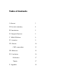
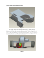
will be absorbed by the frame. Composed of six main parts, shown in figures 1
through 3, the frame will be sturdy and will be able to carry the robots estimated
10 pound weight. Two of the frames components are the same to simplify
manufacturing. The left and right mechanism plate pieces, shown in figure 1, will
support the ball collecting wheel the robot will use to collect the target balls.
Figure 1
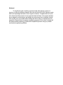
The left and right motor plate pieces in figure 2 will support the motor and wheel
assembly.
Figure 2
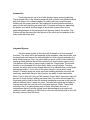
The upper and lower plate pieces, shown in figure 3, will connect perpendicular
to the left and right mechanism and motor plates, completing the frame.
Figure 3
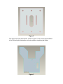
Figure 4 shows the basic assembled frame.
Figure 4
The hopper, shown with collecting tubes in figure 5, will be mounted
between the left and right mechanism plates as shown. The top plate will be cut
out to fit the collecting tubes and the tennis ball tube hopper. The collecting tubes
will be cut from black PVC pipe. And will direct the ball into the hopper once the
retrieval mechanism shoot s the ball in to the robot.
Figure 5
The electronics will fit on the outward face of the right mechanism plate
and will be shielded from any external collisions by the upper and lower plates.
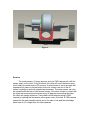
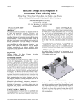
Actuation
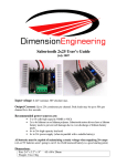
Actuation for this robot will include a tank drive motor train and a spinning
wheel. The two motors that drive the robot will be mounted axially identical on
either side of the robot on the motor mount plates, figure 3 and figure 4, creating
a tank style drive-train. The two identical 12V DC motors were attained from
lynxmotion.com and one is pictured below.
A tank drive set up will allow the robot to move 360 degrees and perform
spins. A ball castor is installed on the rear of the robot to keep it stable while in
motion. To greedily suck up balls into its hopper, the robot will use a high rpm
motor mounted to a soft wheel from a Tamiya brand remote controlled car. The
wheel will be mounted 2.25 inches above the ball. The spinning wheel will then
grab the very top of the ball. The ball will then travel through the robot and into
the hopper. The hopper consists of a tennis ball container that can hold three
balls. The ball grabbing mechanism is shown in figure 6. To run all the motors I
am implementing TPIC0108 motor drivers on my robot.
Figure 6
Sensors
Two sonar sensors, 3 bump sensors, and one CMU camera will outfit the
sensor array on this robot. Fully functional, this robot will avoid obstacles using
two frontally mounted sonar or IR sensors. A sonar sensor is more accurate and
expensive but seems to be the better choice for outdoor use due to the IR
sensor’s inability to deal with unstable environments. The sonar sensor can also
be crossed with little fear of interference issues. If the robot comes in contact with
an object the bump sensors mounted every 90 degrees surrounding the robot,
the robot will change directions. Tennis balls will be detected using a CMU
camera by tracking the fluorescent yellow-green color of the ball. A CMU camera
seems like the most sensible choice due to its ease of use and the knowledge
base here at UF is larger than for other cameras.
Bump
The bump switch mechanism on the robot will consist of a micro switch with an
extended trigger mounted on the perimeter to aid in obstacle avoidance.
The bump sensor will cause the robot to cut power to the motors and change direction in
a random fashion. The goal to implement these sensors will be to mount them and to
program a stop command to the algorithm controlling the motors. The sensors can be
bought from
Mouser Electronics, Inc.
1810 Gillespie Way
Suite 101
El Cajon, CA 92020
(800) 346-6873
and are manufactured by Omron Electronics Part#SS-5GL2. The sensor is not applied to
the robot as of this writing. Six total sensors will be mounted to allow the robot to
navigate in its environment by touch. Normally a micro-switch is wired in parallel to the
power supply and some sort of tool or device that requires a safety switch. When the
switch is activated, the power to the device is cut off to stop the device the switch is
wired to. When a switch is activated, it enables a pin on Port A on the microprocessor to
be written high. The Pin is written high and this causes the motors to stop and then move
in a random direction. No data base is needed on this sensor. It does not return values, so
it is simply a switch to be turned on or off.
Sonar
My sonar sensors consist of sonic devices that will allow the robot to navigate
beyond the touch of the bump sensors by measuring the robots distance away from an
object in its path. A sonar sensor bounces sound pulses from an emitter and waits a short
amount of time to receive the same pulse. The sonar sensor has three objectives to be met
upon completion. The first is to wire them to the microcontroller and mount them. The
second is to activate the sonar’s ability to pulse through software. The third objective will
be to integrate these sensors in to the main program for obstacle avoidance through
external and internal interrupts. These sensors can be bought from:
Acroname Robotics
4822 Sterling Dr.
Boulder, CO 80301-2350
USA
Part # R271-SRF05
720.564.0373
Devantech SRF05
Two Sensors are mounted on the front of the robot on either side at a 45 degree
inward angle and set to pulse at two different times. This array arrangement should
provide the robot with the maximum amount of “vision” with a minimum amount of
sensors. This sensor works by sending out a high pitched pulse of sound activated from
the trigger input pin, which is activated by a falling edge signal from the microcontroller.
The pulse bounces off an object in its path and travels back to the sensor. After waiting
10 micro seconds, the sonar receives the same pulse and sends a signal back to the
microcontroller through the Echo output pin. The microcontroller then calculates the
amount of time has passed between the sonar’s sending and receiving signals and outputs
a distance to the LCD or a command to the motors. The sensor software algorithm uses
ports D and A on the microcontroller, one of the microcontroller’s 16 bit timers, TCNT1,
an interrupt that counts the number of timer overflows, and an External interrupt
activated upon the sonar’s second pulse falling edge signal and uses the microcontrollers
LCD on Port B to blink when ever an interrupt is fired. This algorithm still does not
produce numbers that are consistently between the reasonable range of 0 to 255. Further
debugging is needed before usable values can be obtained. Data values obtained as of this
writing vary from 16 to 1600 nonlinearly, and seem to increase as an object gets closer.
The sonar’s current values seem to contradict to normally operating sonar’s values.
CMU cam
The CMU 01 Robot Vision Cam will be my special sensor used to find tennis
balls using vision processing. This device is designed to return high level vision
capabilities to microprocessor boards that normally would not have enough processing
power to execute such abilities. Four phases of implementation must take place to use the
cameras capabilities. The first is to mount the camera to the robot and interface with the
computer. Second task is to test the cameras abilities. The fourth is to program the
camera through a microcontroller board to track tennis balls using preprogrammed serial
commands. This camera can be bought at;
Images SI Inc.
109 Woods of Arden Road
Staten Island NY 10312
Phone: (718) 966-3694
Part # CMU 01
How sensor is applied
Theory of operation: For the camera to operate a microcontroller must
send serial commands to the CMU camera, and the preprogrammed firmware on the
camera will then use the Track Color command and Middle Mass mode to find the target
ball, a day-glow green tennis ball, track it, while sending commands to the
microcontroller. The microcontroller will then send commands to the motors to drive the
robot towards its intensely colored target. There is no software algorithm written by this
robots creator as of this writing, for CMU cameras firmware code contact any of its
creators:
Anthony Rowe, Charles Rosenberg, or Illah Nourbakhsh, Electrical and Computer
Engineering Computer Science Department Robotics Institute,
Carnegie Mellon University.
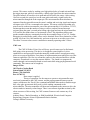
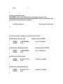
Values were taken from the CMU camera in four separate rooms within the New
Engineering Building on the University of Florida’s campus to test to see what values
could be obtained from different fluorescent lighting sources within the same building.
The camera was mounted on the robot, 6.5 inches above the ground and angled at 45
degrees from the horizontal. The subject tennis ball was always 9 inches away from the
camera lenses. The software that came with the camera did not interface correctly with
the camera so I was forced to use software for a CMU 2 camera. The program could not
average the color of an object so I drew a circle on the ball and took 5 values from within
my marked circle and took the average. The values and cases are presented in Tables 1
through 5. The corresponding graph is Figure 7.
RGB Valu
Room to Room @ NEB rotunda
275
250
225
200
175
150
125
100
75
50
25
0
RED
GREEN
BLUE
Rotunda
North Doors
NW Hall
Vend Hall
5 Sample Average
Figure 7
Table 1
Rotunda Mid-Afternoon (cloudy day)
Point
Red
Green
Blue
1
130
214
16
2
133
175
29
3
153
229
43
4
124
176
35
5
144
180
34
average
136.8
194.8
31.4
Table 2
Rotunda At Night (dim fluorescent light)
Point
Red
Green
Blue
1
127
192
16
2
120
188
23
3
131
163
15
4
120
160
31
5
125
173
22
average
124.6
175.2
21.4
Table 3
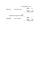
Table 4
Floor Near North Doors at Night (well lit)
Point
Red
Green
Blue
1
240
240
49
2
240
240
61
3
240
240
54
4
240
230
50
5
209
240
41
average
233.8
238
51
North West Hallway At Night (well lit)
Point
Red
Green
Blue
1
240
240
18
2
240
240
16
3
240
240
26
4
240
240
19
5
240
240
35
average
240
240
22.8
Table 5
Vend Machine Hallway @ Night (best lit
fluorescent)
Point
Red
Green
Blue
1
239
240
16
2
233
240
19
3
232
240
17
4
237
240
20
5
240
240
21
average
236.2
240
18.6
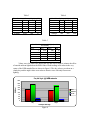
Values were also taken once during the day and once at night to witness the effect
of outside ambient light had on the RGB values. Both readings were taken in the very
center of the NEB rotunda floor as shown in figure 8. The day values were taken on a
cloudy day and the night values were taken to obtain a case with only fluorescent
lighting.
Day Vs Night @ NEB rotunda
225
200
RGB Valu
175
150
125
RED
100
GREEN
BLUE
75
50
25
0
Day
Night
5 Sample Average
Figure 8
Behaviors
Seeking out three tennis balls and collecting them all while avoiding
obstacles will compose of the robots main behaviors. This robot has 3 behaviors:
it avoids obstacles, seeks, and picks up tennis balls. It should perform these
actions quickly as players consume a lot of balls during game play and practice.
The first behavior to be discussed will be the robot’s ability to avoid
objects. Traveling forward, the robot will reverse and change direction if an
obstacle appears within six inches in front of the robot. This behavior is kept
simple by programming the robot to proportionally change direction based on the
values the sonar return
The robot will seek stray tennis balls using its second function: the ability
to seek tennis balls within 1 foot in front of it. When the CMU camera returns a
confidence value greater than thirty percent, meaning the camera is sure to thirty
percent that it is tracking a green blob with the right values, the robot will base its
motor values from the x coordinates also returned by the camera. The x
coordinates used from the camera are normalized and are used as an influence
on how the motors are powered.
Once a ball is found, the robot will perform its third function: picking up
tennis balls. The robot will initially stop to allow the spinning wheel that picks up
the ball, to get up to the necessary collecting speed. The robot will then roll
toward the target and position itself so that its retrieval mechanism will suck the
ball within the robot using the x coordinates returned from the camera. I have
encountered an interesting problem trying to run all 3 motors using the same
timer and PWM signal. When I delay the robot to get the collecting wheel up to
speed to collect the tennis ball the robot will immediately shoot forward. The
robot suddenly shooting forward suggests that the signal I send to the collecting
wheel influences the other motors. I am not sure if this is software or hardware
related. To fix this problem I put the collecting wheel on a separate timer.
CLOSING
Conclusion
Wimbly is currently not where the creator would like the robot to be in any
aspect of the project. The time constraints are tough to meet while leaning the
systems necessary to get a robot completed. The creator of Wimbly should have
taken a class related to microprocessors or digital logic before attempting such a
project. Most of the project composed of the creator trying to get the hardware to
communicate with the microcontroller board. The robot is a successful learning
tool for its creator and the robot can successfully pick up tennis balls. Due to my
lack of hardware programming experience more complex behaviors could not be
implemented due to the tight time constraints. The robots appearance really
needs to be improved and the camera needs to be mounted in a safer position.
The current mounting position puts the sensitive CMU sensor too far up front. If
the robots sensors were to fail, the robot would damage its CMU camera. I
avoided a lot of hassle by listening to what Dr. Schwartz and Arroyo had to say in
class. I saw a lot of failure in other robots that relied on a toy platform or other
inexpensive remanufactured component. If I could start the project over I would
have designed it to be more compact and have the ability to reload the tennis ball
containers when full. I still want to incorporate an IR sensor to let Wimbly know
how many balls it has.
13. Documentation
References:
CMUcam Vision Board User Manual. Anthony Rowe and Carnegie
Mellon University.
Version 1.20, 2004
http://www.seattlerobotics.com/cmucam.htm
Gear Head Motor Datasheet. LynxMotion, Copyright 2000
http://www.lynxmotion.com/ghm02.htm
Devantech SRF05 UltraSonic Range Finder. © 1994-2007,
Acroname Inc.,
http://www.acroname.com/robotics/parts/R93-SRF05.html
MAVRIC-IIB Manual
http://www.bdmicro.com/images/mavric-iib.pdf
Atmega128 Complete Datasheet
http://www.atmel.com/dyn/resources/prod_documents/doc2467.pd
Thanks to:
Kevin Claycomb
Adam Barnett thanks for the advice and all your work on the t tech
Jacob – for all your time and spare parts I thank you. Yea, mechanicals can do it too.
Mike – thanks for the new motor driver board design
Jeff, Don, Mike, Jim , Devin from REU – my coding gurus
Dr. Arroyo and Dr Schwartz – thanks for the opportunity
Sample Code
#include <avr/io.h>
#include <avr/interrupt.h>
#include <util/delay.h>
#include <inttypes.h>
#include <stdlib.h>
#include <stdio.h>
#include <string.h>
#include "camera.h"
#include "LCD.h"
//#include "atmega128_serial.h"
////////////////////////////////Defines//////////////////////////////////////
//DEVINS DEFINE FOR UART INIT()
#define CPU_Speed 16000000L
#define UART0_Baud 19200L
#define UART0_RR ((CPU_Speed/(16L*UART0_Baud))-1)
/////////////////////////////// Prototypes //////////////////////////////////////////////////
void Collect_Wheel();
void Get_Away ();
void Right_Spin();
void Left_Spin();
void Forward_Drivers();
void Forward_Passengers();
void Reverse_Drivers();
void Reverse_Passengers();
/////////////////////////////Global Varibles/////////////////////////////////////////
char b[40];
long int j;
int n;
//
int v[8];
int M;
int middle_x;
int middle_y;
int x_1;
int y_1;
int x_2;
int y_2;
int pixels;
int confidence;
//motor to spool up
int f = 0;
//PWM control globals
int Move_1;
int Move_2;
int S_Factor1;
int S_Factor2;
//
int C_Factor;
for initial timer value
unsigned int MyEndVal;
unsigned int overflowcounter;
int stop;
// when pulse returns to sonar array.
int TimeVal_1;
TimeVal to hold sonar pulse's return time.
int TimeVal_2;
int overflow;
int counter;
int t;
//sonar values
int TimeVal_1 = 0;
int TimeVal_2 = 0;
int main()
{
//////////////////////////// Intialization //////////////////////////////////////////
//PWM (frequency and phase mode)
TCNT3 = 0;
// Declares
TCCR3A |= 0b10101000;
commands for timer 3 register A
TCCR3B |= 0b00010010;
DDRE |= 0b00111000;
ICR3 = 0x064;
DDRA |= 0b11100000;
// clock initialization (sonar ? )
EICRA
|= 0b00001010;
TCCR1B
|= 0b00000001;
sei();
int counter;
//
DDRB |= 0b00000001;
DDRD &= 0b11111100;
DDRA |= 0b00000011;
PORTA
&= 0b11111100;
LCD_Init(20,2);
////////////////////////////////////////////////////////////////////////////////////////////////////////
////////////////////Wills CMU camera code//////////////////////////////////////////
for (j = 0; j < 20000; j++);
// ( ? )LCD_Init(20,2);
LCD_Write_Command(0x01);
camera_init();
LCD_Write_Char(b[0]);
LCD_Write_Char(b[1]);
LCD_Write_Char(b[2]);
LCD_Write_Char(b[3]);
////////////////////////////////////
//
LCD_Write_Command(0x01);
camera_send("TC 100 120 130 150 10 20\r");
camera_recieveM(b);
LCD_Write_Char(b[0]);
LCD_Write_Char(b[1]);
LCD_Write_Char(b[2]);
LCD_Write_Char(b[3]);
for (j = 0; j < 20000; j++);
//
_delay_ms(10000);
LCD_Write_Command(0x01);
while (1)
{
LCD_Write_Command(0x01);
//Clear Display
camera_recieveM(b);
LCD_Goto_Pos(1,0);
sscanf(b,"M \rM %d %d %d %d %d %d %d
%d",&M,&middle_x,&middle_y,&x_1,&x_2,&y_2,&pixels,&confidence); //
these character arrays can now be
LCD_8bit_Out(middle_x);
//used to track a ball with some behavior code
LCD_Write_Char(' ');
LCD_8bit_Out(middle_y);
LCD_Write_Char(' ');
LCD_8bit_Out(x_1);
LCD_Write_Char(' ');
LCD_8bit_Out(x_2);
LCD_Goto_Pos(2,0);
LCD_8bit_Out(y_2);
LCD_Write_Char(' ');
LCD_8bit_Out(pixels);
LCD_Write_Char(' ');
LCD_8bit_Out(confidence);
//OCR3C = 0; //
stop collecting wheel, safety
if (confidence > 20) //pixels, capped at 255. confidence,
capped at 255
{
//C_Factor =
30;
Collect_Wheel(); // spin collecting wheel
f = 0;
if (f = 0)
{
OCR3A = 0;
OCR3B = 0;
LCD_Write_Char('S');
LCD_Write_Char('T');
LCD_Write_Char('O');
LCD_Write_Char('P');
for (j = 0; j < 20000; j++);
// play with value
for (j = 0; j < 20000; j++);
for (j = 0; j < 20000; j++);
for (j = 0; j < 20000; j++);
}
// camera reosolution is 80x143
if (middle_x < 30)
// both
motors
{
PORTA |=0b11000000;
// set
1 is forward,
Move_1 = 30;
OCR3A = Move_1;
OCR3B = Move_1 -5;
}
else if (middle_x > 50)
// both
motors
{
//OCR3A = 0;
PORTA |=0b11000000;
// set 1 is forward,
Move_2 = 30; // ? /4 (?)
OCR3B = Move_2;
OCR3A = Move_2 -5;
}
else
//
when 35 > v[1] < 45
{
PORTA |=0b11000000;
move both motors forward,
OCR3B = 30;
//
OCR3A = 30 ;
}
collecting wheel
f = 1; // for (f = 0 ; f = 1;
_delay_ms(10000));
}
else
{
for(t = 0; t < 3; t++)
{
//ball collecting stuff
OCR3C = 0; //
stop
collecting wheel
f = 0;
1;_delay_ms(10000)); to reset variable to wait for motor
//for (f = 0 ; f =
//Sonar 1
EIMSK
|= 0b00000001;
TIMSK
|= 0b00000100;
PORTA |= 0b00000001;
_delay_us (10);
PORTA &= 0b11111110;
MyStartVal = TCNT1;
overflowcounter = 0;
stop = 0 ;
used to wait for interupt to fire
// variable
while(stop == 0)
{/* if stop = 0, do nothing
and wait)*/}
EIMSK &= 0b11111110;
TimeVal_1 +=
(overflow*16)+((MyEndVal - MyStartVal)/
//Sonar 2
EIMSK
|=
TIMSK
|=
0b00000010;
0b00000100;
PORTA |= 0b00000010;
_delay_us (10);
microseconds
// wait for 10
PORTA &= 0b11111101;
MyStartVal = TCNT1;
//
named TCNT1.
overflowcounter = 0;
// variable used to
stop = 0 ;
wait for interupt to fire
while(stop == 0)
{/* if stop = 0, do nothing
and wait)*/}
TimeVal_2 +=
(overflow*16)+((MyEndVal - MyStartVal)/4096
EIMSK &= 0b11111101 ;
// clears bit to turn off external interupt INT1
}
// for for(t = 0; t < 5; t++) loop
LCD_Write_Command(0x01);
//Clear Display
if (t == 3)
{
TimeVal_1 /= 3;
TimeVal_2 /= 3;
// display sonar
LCD_Goto_Pos(2,12);
LCD_8bit_Out(TimeVal_1);
LCD_Goto_Pos(2,16);
LCD_8bit_Out(TimeVal_2);
t = 0;
}
Get_Away ();
} //End of else
}// End of while loop
}// End of main loop
///////////////////////////////////////////Sonar Interrupts/////////////////////////////////////////
//Falling edge signal interrupt for sonar 1
ISR(INT0_vect) // Put Atmel defined interupt vector in the ()'s and Note:
{
MyEndVal = TCNT1;
// Variable used to read the 16
bit microprocessor timer 1 //
read TCNT1 here to read value of timer after
interupt has fired.
overflow = overflowcounter;
stop = 1;
sei();
//
}
//Falling edge signal interrupt for sonar 2
ISR(INT1_vect) // Put Atmel defined interupt vector in the ()'s and Note:
{
MyEndVal = TCNT1;
// Variable used to read the 16
bit microprocessor timer 1 //
read TCNT1 here to read value of timer after
interupt has fired.
overflow = overflowcounter;
stop = 1;
sei();
//
}
//Timer Overflow Interrupt
ISR(TIMER1_OVF_vect) //INterupts are functions that run in the
background and are fired when their programmed event has occoured, this
interupt fires when the time overflows.
{
overflowcounter++;
//increment counter here
}
//////////////////////////////// functions ////////////////////////////////////////
void Forward_Drivers(void)
{
PORTA
|= 0b10000000;
OCR3B
= 45;
}
void Forward_Passengers(void)
{
PORTA
|= 0b01000000;
OCR3A
= 45;
}
void Reverse_Drivers(void)
{
PORTA
&= 0b01111111;
OCR3B
= 45;
//drivers side is OCR3B
// set 1 is forward
//drivers side is OCR3B
// set 1 is forward
// clear 0 is reverse
}
void Reverse_Passengers(void)
{
PORTA
&= 0b10111111;
OCR3A
= 45;
}
// clear 0 is reverse
void Drivers_Spin (void)
{
Forward_Drivers();
Reverse_Passengers();
}
void Passengers_Spin(void)
{
Forward_Passengers();
Reverse_Drivers();
}
void Collect_Wheel(void)
{
PORTA |= 0b00100000;
OCR3C = 70;
}
void Get_Away(void)
{
if (TimeVal_2 > 60 )
{
Forward_Drivers();
}
else if (TimeVal_2 < 30)
{
PORTA
&=
0b01111111;
// clear 0 is reverse
//
}
OCR3B
= 50;
_delay_ms (100);
else
// proportional control for one motor
{
PORTA
0b10000000;
|=
// set 1 is forward
OCR3B
= 30;
//_delay_ms (100);
}
if (TimeVal_1 > 60)
{
Forward_Passengers();
}
else if (TimeVal_1 < 30)
{
PORTA
0b10111111;
&=
// clear 0 is reverse
//
}
OCR3A
= 50;
_delay_ms (100);
else
// proportional control for one motor
{
PORTA
0b01000000;
//
}
}
|=
// set 1 is forward
OCR3A
= 30;
_delay_ms (100);