1
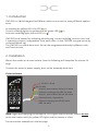
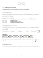
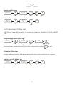
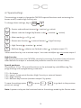
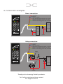
secure open Code & Mifare CM1000 Mykey - Art. No: 480010 (black), 480011 (white) Classic - Art. No.: 482010 (black), 482011 (white) User manual CM1000_usermanual_ENGmay15 Conlan ApS • Speditorvej 2A • DK-9000 Aalborg • Tel: +45 72 40 60 03 • Fax: +45 96 32 00 22 www.conlan.eu • [email protected] Table of contents 1.Introduction page 3 2.Installation page 3 3. Programming users 3.1 User positions 3.2 Programming user codes 3.3 Programming Mifare tags 3.4 Programming codes/Mifare tags for special functions 3.5 Smart reading page 4 page 4 page 4 page 5 4. Configuration of CM1000 4.1 Service code 4.2 Configuration overview 4.3 Change the Master code 4.4 Change the Service code 4.5 LED Indications 4.6Outputs 4.7 Special settings page 6 page 6 page 7 page 7 page 7 page 7 page 8 page 8 page 9 page 10 5. Backup card page 11 6.Blocking 7. Manual reset 8. Technical specifications page 11 9. Connection examples page 12 page 11 page 11 2 1. Introduction CM1000 is a flexible keypad and Mifare reader in one unit for many different applications. In standby the yellow LED is lit LED (● ○ ○) Correct code/tag lights the yellow and the green LED (● ● ○) Incorrect code/tag lights the red LED (○ ○ ●) CM1000 has a buzzer for indicating while keying, correct code/tag, incorrect etc. and 2 transistor outputs, independant from each other, so the CM1000 can give access by code and Mifare tag. The CM1000 is a stand alone unit, the can be programmed directly by Master code and Service code. 2. Installation Mount the reader on a even surface. (use the following drill template for precise fitting). Connect the wires to power supply, door strike, assembly board etc. Colour scheme Prox 9 - 25 VDC / 30 mA 0V GND 1 2 3 4 5 6 7 8 9 0 Output 2 open collector, 500 mA, 0V active External controlling green LED, 0V active Output 1 open collector 500 mA, 0V active External buzzer / high security External controlling red LED, 0V active REX, 0V active CT 2000 Prox ALARM SYSTEM A/S Note: Right after applying the voltage all LED’s lights and the buzzer sounds do not touch the reader untill the yellow LED lights and the buzzer is silent. See connection examples on the last page. 3 3. Programming users Programming the CM1000 is simple and easy to understand. 3.1 User positions CM1000 has 200 positions, which can contain a code or a Mifare tag. The positions are divided as following: User position 1 - 100 101 - 150 151 - 190 191 - 200 Function Activates output 2 (the code in position 1 is 1234 - default) Activates output 1 Activates output 1 and 2 Reserved for special functions 3.2 Programming user codes The Master code is used to program/change/delete the users. By default the Master code is 4711. LED indication: No light: ○ Light: ● Flash: * Clear buffer: New users Master code # (4711 - standard) ○●○ Key in the Key in the user position # ●●○ Key in the user code # ●●○○●○ To program more users, continue from “key in the user position” or press # to exit. ●○○ Changing user codes It’s the same procedure as programming new users, just overwrite the user positions. 4 Delete specific users Master code # (4711 - standard) ○●○ Key in the Key in the user position # # # ●●○ ○●○ ●○○ # # ○○● ○● ●○○ Delete all users Master code # (4711 - standard) ○●○ Key in the Key in 2500 3.2 Programming Mifare tags CM1000 can read Mifare classic 1K, classic 4K, Ultralight, Ultralight C, PLUS and DESFIRE. Programming a new Mifare tag Master code # (4711 - standard) ○●○ Key in the Key in the user position # # Show Mifare tag ●●○ ●●○○●○ For more tags, continue from “key in the user position or type # to exit. ●○○ Changing Mifare tags It’s the same procedure as programming new users, just overwrite the position. Delete a specific Mifare tag Master code # (4711 - standard) ○●○ Key in the Key in the user postion # # # ●●○ ○●○ ●○○ 5 3.4 Programming codes/Mifare tags for special functions Programming the codes and Mifare tags is described in 3.2 and 3.3. This entry activates the output(s) for 5 seconds (factory setting). Only 1 user can enter at the time. Programming the same user twice By programming the same code/Mifare tag on the same position twice toggles the output. (Ie. the code/Mifare tag is entered to unlock the door and entered to lock it again). Programming the same user 3 times By programming the same code/Mifare tag on the same position 3 times, the output is designated as switch on only. (Ie. the door is permanently unlocked when the code/Mifare tag is entered). Programming the same user 4 times By programming the same code/Mifare tag on the same position 4 times, the output is designated as switch off only. (Ie. the door is only locked when the code/Mifare tag is entered). 3.5 Smart reading This position makes it possible to program codes/Mifare tags quickier without entering new positions. Key in a position and it counts automatically to the next position. Codes and Mifae tags can be programmed alternatively as you see fit. Key in the Master code # ○●○ Key in 05 # Key in the starting position *●○ # Key in the code *○○ For more codes/tags repeat from here Note: This programming mode overwrites existing positions. 6 or show tag # 4. Configuration of CM1000 4.1 The Service code The Service code is used for CM1000’s advanced settings such as changing the Master code and Service code, LED indications and much more. The overview of the settings and the factory settings can be seen in 4.2 Configuration overview. The Service code is 12347890 (factory setting). Note: Before the Service code can be used must the voltage be turned OFF and ON (the Service code can now be entered within 10 seconds). After entering the Service code the reader is in programming mode (the green LED lights). Each time a setting is made the CM1000 goes back to the previous point and the next setting can be made. The navigation is by entering the position/ value followed by #. 4.2 Configuration overview Position SettingFactory default 00 Master code (1 til 8 cifre) 4711 01 Service code (1 til 8 cifre) 12347890 02 LED indications Normal = Yellow, active = Yellow and green 03 Outputs Output time for 1 and 2 is 5 seconds 04 Special functions 05 Smart reading 06 Background light 08 Backup/cloning the settings 2500 Alle codes/Mifare tags on the user positions are deleted 0250 Reset to factory default 4.3 Change the Master code By default the Master code is 4711 and can only be used to program, change or delete users on the CM1000. To change the Master code, enter the following: Key in the Service code # ○●○ Key in 00 # Key in a new code or show tag ●●○ # ○●○ 7 4.4 Change the Service code The Service code is used to configurate the CM1000’s settings. To change the Service code, enter the following within 10 seconds after power on: # Key in the Service code # Key in 01 ○●○ # Key in a new code or show tag ●●○ Repeat new code/tag **○ # ○●○ 4.5 LED indications The CM1000’s 3 LED’s can be adjusted at will. To adjust the LED indications enter the following: 02 # *** 1 # adjust the LED’s for standby indication (normal). *** 2 # adjust the LED’s for correct code/tag indication (active). *** 3 # adjust the keying indication (how the LED will react while keying). *** To adjust the LED’s press on the following: 1 = yellow LED (toggle by press) 2 = green LED (toggle by press) 3 = red LED (toggle by press) 0 = buzzer (works only on active and keying indication (toggle by press)) # = save and go one step back To save the settings press point (not saving). # or press 8 % * / to go back to the previous 4.6 Outputs The CM1000 has 2 transistor outputs, which both are activated for 5 seconds (factory default) when a correct code/Mifare tag is entered. The output activation time can be changed and inverted. To cahnge these settings key in: 02 # ○●● 1 # acitvation time for output 1 (white core) 2 # activation time for output 2 (yellow core) The time is set as: Key in hours 0 to 60 # # Key in minutes ●○○ 0 to 60 Key in seconds 0 to 60 ○●○ # ○○● If no value is entered in hours, minutes or seconds is the value automatically 0 (which corresonds to set the output as toggle). 3 # bonding the positions and output 1 4 # bonding the positions and output 2 Both outputs are bonded to specific positions. By factory default positions 1 to 100 are bounded to output 2 and positions 101 to 150 to output 1. The value can not be crossed. inverted outputs 5 # 1 output 1 (● ○ ○ = inverted / ○ ○ ○ = not inverted) 2 output 2 (○ ● ○ = inverted / ○ ○ ○ = not inverted) To save the settings press point (not saving). # or press 9 % * / to go back to the previous 4.7 Special settings These settings is used to change the CM1000’s special functions such as turning the buzzer on/off, enable High Security etc. To change these settings, key in: 04 # ●○○ 1 = Service code without timeout (● = inactive / ● = active) 2 = Master code be changed by Master code (● = inactive / ● = active) 3 = Mute reader (● = off / ● = on) 4 = Brown wire function (● = external buzzer / ● = High Security) 5 = High Security (● = inactive / ● = active) 6 = Bell/star key (● = delete non-finished codes / ● = activates output 1*) *When the bell/star key is set to activate output 1 can codes and Mifare tags only activate output 2. High Security High Security increases the CM1000’s security by ensuring 2 positions have to be activated before the output is activated (the positions must be next to each other). Special positions On positions 191 to 194 special functions can be activated by code/Mifare tag. The programming is like programming a new user. 191 = No buzzer 192 = Input 1 (brown wire) function (High Security or external buzzer) 193 = High Security 194 = Bell/star key function (activates output 2 by press) To save the settings press point (not saving). # or press % * / to go back to the previous Note: A power cucle puts the functions back to the settings made by the Service code. 10 5. Backup card The CM1000’s informations can be saved and loaded with a Backup card (Art. No.: 480080). Please view the following configuration scheme for further information. 6. Blocking The CM1000 is blocked for 1 minute after 4 incorrect codes/Mifare tags. LED indication: ○ ○ * 7. Manual reset The CM1000 can be reset to factoty default manually. • Turn the voltage off. • Connect the yellow and brown wire. • Turn the voltage on (9 - 25 VDC) the readers LED’s lights and the buzzer sounds. • Turn the voltage off and disconnect the yellow and brown wire. The CM1000 is now reset to factory default and the user codes/tags are deleted. 8. Technical specifications Voltage: Voltage range: Mifare reading: Output: Input: Protection rate: Color: Cable: Dimensions (HxWxD): 12 VDC, 30 mA 9 - 25 VDC Max. 50 mm 2x open collector, max. 500 mA External buzzer/High Security (brown) and REX, 0V active (blue) IP67 Black or white 2,5 m white, 8 cores Mykey = 76x49x8 mm / Classic =130x50x8 mm 11 9. Connection examples Direct connection Prox 1 2 3 4 5 6 7 8 9 +12V DC 0V DC REX, 0V active High Security/external buzzer, 0V active External controlling red LED, 0V active External controlling green LED, 0V active 0V GND 0 0V GND + 12V DC + 12V DC Doorstrike CT 2000 Prox ALARM SYSTEM A/S + 12V DC Doorstrike + 12V DC Relay connection Prox 1 2 3 4 5 6 7 8 9 +12V DC 0V DC REX, 0V active Hight Security/external buzzer, 0V active External controlling red LED, 0V active External controlling green LED, 0V active Relay 0V C NC 0 NO 0V GND Relay CT 2000 Prox ALARM SYSTEM A/S + 12V DC Doorstrike + 12V DC + 12V DC Thank you for choosing Conlan’s products. For further assistance please contact our support service