1
YT1-1605-000
ENGLISH
For use with Network Camera VB-M600D/VB-M600VE
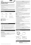
Recessed Mounting Kit SR600-VB
Installation Guide
The recessed mounting kit SR600-VB is an optional product for exclusive use with VB-M600D/VB-M600VE (hereafter
referred to as the camera). The camera is recessed into a ceiling or wall for a clean appearance.
This “Installation Guide” explains the installation procedure using the recessed mounting kit SR600-VB. Be sure
to read the “Safety Precautions” section for correct use. After reading this “Installation Guide”, keep it in a readily
accessible location for future reference.
In addition to this “Installation Guide”, also read the camera-bundled “VB-M600D/VB-M600VE Installation Guide” and
“VB-M700F/VB-M600D/VB-M600VE Operation Guide” (included in the Setup CD-ROM).
* For the latest information (firmware and bundled software, User’s Manuals, operating environment, etc.) please
check our website.
Caution
Request a professional installer for all camera installation work. Never try to install the
camera by yourself. Doing so may result in unforeseen accidents such as dropping
the camera or electric shock.
Check Bundled Items
This product comes with the following items. If any item is missing, contact the dealer where you purchased the
product.
Caution
For installation or inspection of this camera, consult the dealer where you purchased the product.
• This installation should be made by a qualified service person and should conform to all local codes.
• When installing on a ceiling, make sure the surface is capable of withstanding the total weight of the
recessed mounting kit and the camera and is sufficiently reinforced if necessary.
• Periodically check the ceiling brackets and screws for rust and loose material to prevent injuries and
equipment damage due to falling items.
• Do not install in unstable places, places subject to significant vibration or impact, or places subject to
salt damage or corrosive gas.
• Be sure to attach the camera-bundled safety wire to the camera during installation.
• Use exclusively with the camera.
Failure to do so may result in the camera falling or other accidents.
• Do not touch the edge of metal parts with bare hands.
• Do not insert your finger in the space between the brackets and the ceiling.
Injury may result.
Caution
• Do not install the camera on an unstable surface.
• To maximize shock resistant specifications, do not install on insufficiently strong surfaces or surfaces
subject to significant vibration (VB-M600VE).
Malfunction may result.
• Take care not to damage wiring or pipes in the room.
Damage to peripheral items may result.
Precautions for Mounting the Camera Underneath Eaves (VB-M600VE)
1. Recessed mounting cover 1
2. Ceiling bracket 1 1
For installation of VB-M600VE underneath eaves, proceed carefully to retain waterproof/dustproof
capabilities.
Be sure to read “Precautions for Mounting the Camera Underneath Eaves” in the “VB-M600D/VB-M600VE
Installation Guide”.
3. Ceiling bracket 2 1
Precautions for Use
6. Camera fixing screws (M4) 3
Warning
7. Assemble screws (M3) 3
4. Backside ceiling bracket 2
8. Ceiling bracket screws (M4) 3
5. Template 1
9. Installation Guide (This document) 1
• If you discover defective conditions such as smoke, strange sounds, heat or strange odors,
immediately stop using the camera and contact your closest dealer..
Continued use may cause fire or electric shock.
•
•
•
•
•
•
Do not disassemble or modify the camera.
Do not damage the connecting cable and others.
Do not spill water or other liquid inside the camera, spray the camera with water, or otherwise make it wet.
Do not insert foreign objects into the camera.
Do not use flammable sprays near the camera.
Do not leave LAN cables, external power supplies or AC adapter (optional) power connectors connected
when the camera is not in use for long periods.
• Do not use flammable solvents such as alcohol, paint thinner or benzine when cleaning the camera.
Fire or electric shock may result.
© CANON INC. 2011
Printed in Taiwan
Notes on Power Supply
Warning
Symbols Indicating Safety Precautions
This "Installation Guide" uses the following marks to indicate important information the user should know in
order to use the product safely. Be sure to observe these items.
Warning
Inappropriate handling against the instruction accompanied by this sign may
result in death or serious injury. Be sure to observe these warnings to ensure
safety.
Caution
Inappropriate handling against the instruction accompanied by this sign may
result in injury. Be sure to observe these precautions to ensure safety.
• After turning off the power, wait for at least five seconds before turning the power on again. If the
power is turned on again too quickly, the camera may operate poorly.
This symbol indicates important or restricted items. Be sure to read this section.
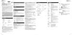
External Dimensions
Recessed mounting cover
This section explains precautions that must be observed when using the camera. If they are not observed,
injury, death and/or property damage may occur. Read the following information carefully and be sure to
observe the precautions.
3- 5
( 0.20)
Backside ceiling brackets
12
0˚
4)
8.9
7(
7.0 ( 0.28)
22
120˚
Height
):
95
7.
76.5
(3.01)
76.5
(3.01)
75.5
(2.97)
Attached to VB-M600VE
78.5
(3.09)
Attached to VB-M600D
Circumscribed
circle diameter
123 (4.84)
123 (4.84)
152 (5.98)
Warning
10.0 (0.39)
2(
20
125 ( 4.92)
Installation Precautions
Do not install in the following places:
• Places in strong direct sunlight, near heat-generating objects, or subject to high temperatures
• Places near fire sources or flammable solvents (alcohol, thinner, etc.)
• Humid or dusty places
• Places subject to lamp black or steam
• Places subject to sea air
• Confined or enclosed places
Fire or electric shock may result.
Ceiling bracket
155 (6.10)
Safety Precautions
18
(0.71)
Important
Caution
247 ( 9.72)
Caution
Inappropriate handling against the instruction accompanied by this sign may result
in property damage. Be sure to observe these precautions.
• Only use the dedicated AC adapter PA-V17 (optional) for AC power.
• Do not set any heavy objects on the power cable.
• Do not pull, forcibly bend, scratch, or modify the power cable.
• Do not cover or wrap the AC adapter (optional) with cloth or blankets.
Fire or electric shock may result.
Be sure to read the User’s Manual for the PA-V17 (optional) before use.
Unit: mm (in.)
Main Specifications
Model
Type
Network camera-mounting
environments
Dimensions
Weight
SR600VBIG_E.indd 1
SR600-VB
Silver
VB-M600D Temperature: -10 – 50 °C (14 – 122°F) / Humidity: 5 – 85% (without condensation)
VB-M600VE Temperature: -10 – 50 °C (14 – 122°F) / Humidity: 5 – 85% (without condensation)
Temperature: -30 – 50 °C (-22 – 122°F) / Humidity: 5 – 85% (without condensation)
*equipped with an optional Heater Unit HU600-VB
VB-M600D (Φ x H) Φ 247 x 83 mm (Φ 9.72 x 3.27 in.)
VB-M600VE (Φ x H) Φ 247 x 90 mm (Φ 9.72 x 3.54 in.)
Approx. 687 g (1.52 lb.) (excluding camera)
2011/06/17 14:26:29
2
Installing the Camera
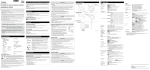
The following explains the procedures to install the camera on a ceiling using the recessed mounting kit.
Before installing the camera, set the IP address and other network information on the camera using the “VB Initial
Setting Tool” on the Setup CD-ROM.
For details on how to operate the “VB Initial Setting Tool,” see “VB-M700F/VB-M600D/VB-M600VE Operation Guide”.
If using an SD memory card, insert the SD memory card into the camera before attaching the dome case (see “Using
an SD Memory Card” in “VB-M600D/VB-M600VE Installation Guide”).
VB-M600D
VB-M600VE
Bundled
screw
M3 × 3
Embossed
locating pins
1 Determine an installation position for the camera and drill holes in the ceiling
Use the bundled template to determine the positions of the holes (three) for mounting the backside ceiling bracket
and the ceiling bracket holes according to the camera orientation. Next, drill holes in the ceiling.
3
4
VB-M600D
2 Assemble the ceiling brackets
VB-M600VE
Lock screw
holes
Inner cover
Interlock the embossed locating pins of ceiling bracket 1 with the locating bores in ceiling bracket 2. Fix the
brackets with the 3 bundled assemble screws (M3).
The position of the locating bores on ceiling bracket 2 differs according to the camera. Refer to the diagram to
interlock the brackets correctly.
Important
Dome case
Check that the interlocked brackets are fixed by the embossed locating pins.
* Diagram of VB-M600D.
3 Loosen the three lock screws on the dome case and remove the dome case
VB-M600VE
5
VB-M600D
Special tamper-resistant screws are used for the dome case lock screws. Use the dome case lock screw wrench
bundled with the camera.
VB-M600VE
When guiding cables through the side
4 Remove the inner cover
When guiding cables through the ceiling
wiring hole
Remove the 4 pieces of tape that prevent lens rotation during shipping, and push the inner cover in the direction of
the arrows to remove it. Then remove the 2 pieces of tape attached to the base of the lens.
5 Open the wiring hole according to the installation method
VB-M600D
Use a box cutter to cut a cross shape into the wiring hole cover in order to guide cables through.
Do not remove the wiring hole cover.
6
Bundled
screw
M4 × 3
VB-M600D
VB-M600VE
VB-M600VE
Use a coin to unscrew the wiring hole cover from the side through which cables will be guided. Screw the wiring
hole cover into the other wiring hole. You can fit a composite pipe (NPT 3/4 inch threaded hole) to the wiring hole.
6 Mount the camera to the ceiling bracket assembly
Fix with three bundled camera fixing screws (M4).
The screw holes differ according to the camera. Refer to the diagram to fix the camera using the correct screw
holes.
* Diagram of VB-M600D.
7 Attach the backside ceiling brackets inside the ceiling
7
9
8
From the inside of the ceiling, insert the protrusions on the backside ceiling brackets through the mounting holes
drilled in step 1.
8 Temporarily tighten screws to the backside ceiling brackets
Temporarily tighten the three bundled ceiling bracket screws (M4) through the ceiling.
Bundled
screw
M4 × 3
9 Secure the safety wire
* Diagram of VB-M600D.
11
Securely attach the camera-bundled safety wire to an anchor or structure. After securing one end of the safety
wire to the ceiling, secure the other end to the camera using the screw that is fastened to the camera.
10 Guide the LAN cable through the wiring hole
13
When using an external power supply, guide the power interface cable through the wiring hole. Guide the I/O
interface cable and the audio interface cable (bundled with the camera) through the wiring hole if necessary.
Important
Cable tie
When using the AC adapter PA-V17 (optional), cut the cable tie and remove the ferrite core. Be
sure not to damage the power cable when cutting the cable tie.
* Diagram of VB-M600D.
* Diagram of VB-M600D.
11 Fix the camera-mounted ceiling bracket assembly to the ceiling
14
Position the ceiling bracket assembly onto the screws temporarily tightened in step 8, turn clockwise and
completely fasten the screws.
15
VB-M600D
VB-M600VE
12 Wire the cables
Wire the cables referring to the “Cable Wiring Method” in the “VB-M600D/VB-M600VE Installation Guide”.
13 Attach the inner cover
Dome case
Attach the inner cover to its original position.
* Diagram of VB-M600D.
14 Attach the dome case
Firmly fix the dome case at three points to the camera using the dome case screws.
15 Attach the recessed mounting cover
Safety wire
Secure to an anchor
or structure
Ceiling bracket assembly
LAN cable
Align the (O) mark on the recessed mounting cover with the (I) mark on the ceiling bracket, and turn clockwise
until the (I) mark on the recessed mounting cover aligns with the (I) mark on the ceiling bracket. Fix the recessed
mounting cover.
Backside ceiling brackets
16 Set the camera angle
Dome
Main unit
SR600VBIG_E.indd 2
Ceiling board
* Diagram of VB-M600D.
When installation is complete, use the Camera Angle Setting Tool to adjust the pan, tilt, rotation, zoom (and focus)
(See “Camera Angle Setting Tool” in the “VB-M700F/VB-M600D/VB-M600VE Operation Guide”.
2011/06/17 14:26:31