1
2
Installing the Camera
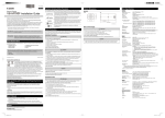
The following explains the procedures to install the camera on a ceiling using the recessed mounting kit.
Before installing the camera, set the IP address and other network information on the camera using the “VB Initial
Setting Tool” on the Setup CD-ROM.
For details on how to operate the “VB Initial Setting Tool,” see “VB-M700F/VB-M600D/VB-M600VE Operation Guide”.
If using an SD memory card, insert the SD memory card into the camera before attaching the dome case (see “Using
an SD Memory Card” in “VB-M600D/VB-M600VE Installation Guide”).
VB-M600D
VB-M600VE
Bundled
screw
M3 × 3
Embossed
locating pins
1 Determine an installation position for the camera and drill holes in the ceiling
Use the bundled template to determine the positions of the holes (three) for mounting the backside ceiling bracket
and the ceiling bracket holes according to the camera orientation. Next, drill holes in the ceiling.
3
4
VB-M600D
2 Assemble the ceiling brackets
VB-M600VE
Lock screw
holes
Inner cover
Interlock the embossed locating pins of ceiling bracket 1 with the locating bores in ceiling bracket 2. Fix the
brackets with the 3 bundled assemble screws (M3).
The position of the locating bores on ceiling bracket 2 differs according to the camera. Refer to the diagram to
interlock the brackets correctly.
Important
Dome case
Check that the interlocked brackets are fixed by the embossed locating pins.
* Diagram of VB-M600D.
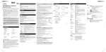
3 Loosen the three lock screws on the dome case and remove the dome case
VB-M600VE
5
VB-M600D
Special tamper-resistant screws are used for the dome case lock screws. Use the dome case lock screw wrench
bundled with the camera.
VB-M600VE
When guiding cables through the side
4 Remove the inner cover
When guiding cables through the ceiling
wiring hole
Remove the 4 pieces of tape that prevent lens rotation during shipping, and push the inner cover in the direction of
the arrows to remove it. Then remove the 2 pieces of tape attached to the base of the lens.
5 Open the wiring hole according to the installation method
VB-M600D
Use a box cutter to cut a cross shape into the wiring hole cover in order to guide cables through.
Do not remove the wiring hole cover.
6
Bundled
screw
M4 × 3
VB-M600D
VB-M600VE
VB-M600VE
Use a coin to unscrew the wiring hole cover from the side through which cables will be guided. Screw the wiring
hole cover into the other wiring hole. You can fit a composite pipe (NPT 3/4 inch threaded hole) to the wiring hole.
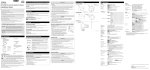
6 Mount the camera to the ceiling bracket assembly
Fix with three bundled camera fixing screws (M4).
The screw holes differ according to the camera. Refer to the diagram to fix the camera using the correct screw
holes.
* Diagram of VB-M600D.
7 Attach the backside ceiling brackets inside the ceiling
7
9
8
From the inside of the ceiling, insert the protrusions on the backside ceiling brackets through the mounting holes
drilled in step 1.
8 Temporarily tighten screws to the backside ceiling brackets
Temporarily tighten the three bundled ceiling bracket screws (M4) through the ceiling.
Bundled
screw
M4 × 3
9 Secure the safety wire
* Diagram of VB-M600D.
11
Securely attach the camera-bundled safety wire to an anchor or structure. After securing one end of the safety
wire to the ceiling, secure the other end to the camera using the screw that is fastened to the camera.
10 Guide the LAN cable through the wiring hole
13
When using an external power supply, guide the power interface cable through the wiring hole. Guide the I/O
interface cable and the audio interface cable (bundled with the camera) through the wiring hole if necessary.
Important
Cable tie
When using the AC adapter PA-V17 (optional), cut the cable tie and remove the ferrite core. Be
sure not to damage the power cable when cutting the cable tie.
* Diagram of VB-M600D.
* Diagram of VB-M600D.
11 Fix the camera-mounted ceiling bracket assembly to the ceiling
14
Position the ceiling bracket assembly onto the screws temporarily tightened in step 8, turn clockwise and
completely fasten the screws.
15
VB-M600D
VB-M600VE
12 Wire the cables
Wire the cables referring to the “Cable Wiring Method” in the “VB-M600D/VB-M600VE Installation Guide”.
13 Attach the inner cover
Dome case
Attach the inner cover to its original position.
* Diagram of VB-M600D.
14 Attach the dome case
Firmly fix the dome case at three points to the camera using the dome case screws.
15 Attach the recessed mounting cover
Safety wire
Secure to an anchor
or structure
Ceiling bracket assembly
LAN cable
Align the (O) mark on the recessed mounting cover with the (I) mark on the ceiling bracket, and turn clockwise
until the (I) mark on the recessed mounting cover aligns with the (I) mark on the ceiling bracket. Fix the recessed
mounting cover.
Backside ceiling brackets
16 Set the camera angle
Dome
Main unit
SR600VBIG_E.indd 2
Ceiling board
* Diagram of VB-M600D.
When installation is complete, use the Camera Angle Setting Tool to adjust the pan, tilt, rotation, zoom (and focus)
(See “Camera Angle Setting Tool” in the “VB-M700F/VB-M600D/VB-M600VE Operation Guide”.
2011/06/17 14:26:31