1
YT1-1606-000
Network Camera
Installation Guide
Thank you for purchasing Canon Network Camera VB-M700F (hereafter referred to as the
camera). The camera is for indoor use only.
Be sure to read “Installation Guide” (this document) and “VB-M700F/VB-M600D/VB-M600VE
Operation Guide” (included in the Setup CD-ROM) before use.
This Installation Guide explains the mounting method of the camera. Be sure to read the “Safety
Precautions” section for correct use. After reading this Installation Guide, keep it in a readily
accessible location for future reference. The detailed procedures for using this camera are
explained in the “VB-M700F/VB-M600D/VB-M600VE Operation Guide”. Read these guides
carefully before using the camera to ensure correct use.
Symbols Indicating Safety Precautions
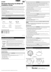
External Dimensions
This Installation Guide uses the following marks to indicate important information the
user should know in order to use the product safely. Be sure to observe these items.
VB-M700F
Warning
Inappropriate handling against the instruction accompanied by
this sign may result in death or serious injury. Be sure to observe
these warnings to ensure safety.
Caution
Inappropriate handling against the instruction accompanied
by this sign may result in injury. Be sure to observe these
precautions to ensure safety.
Caution
Important
Note
Caution
Request a professional installer for all camera installation work.
Never try to install the camera by yourself. Doing so may result in
unforeseen accidents such as dropping the camera or electric shock.
Contains reference information for operation or additional
explanations.
This product comes with the following items. If any item is missing, contact the dealer where you
purchased the product.
1.VB-M700F main unit
4. Installation Guide (This document)
2. Power connector
5. Warranty card
3. Setup CD-ROM
6. Notice
192 (7.56)
Night Mode (monochrome):
Unit: mm (in.)
Notes on Power Supply
Warning
This section explains precautions that must be observed when using the camera. If they
are not observed, injury, death and/or property damage may occur. Read the following
information carefully and be sure to observe the precautions.
Serial No.
_________________________________
MAC Address
_________________________________
© CANON INC. 2011
Warning
Do not install in the following places:
• Places in strong direct sunlight, near heat-generating objects, or subject to high
temperatures
• Places near fire sources or flammable solvents (alcohol, thinner, etc.)
• Humid or dusty places
• Places subject to lamp black or steam
• Places subject to sea air
• Confined or enclosed places
Fire or electric shock may result.
Write the serial number and MAC address of the camera (printed on the seal at the top of the
camera) in the field below before storing this Installation Guide in a safe location.
Printed in Taiwan
European Union (and EEA) only.
These symbols indicate that this product is not to be disposed of with your
household waste, according to the WEEE Directive (2002/96/EC), the Battery
Directive (2006/66/EC) and/or your national laws implementing those Directives.
If a chemical symbol is printed beneath the symbol shown above, in
accordance with the Battery Directive, this indicates that a heavy metal
(Hg = Mercury, Cd = Cadmium, Pb = Lead) is present in this battery or
accumulator at a concentration above an applicable threshold specified in the Battery Directive.
This product should be handed over to a designated collection point, e.g., on an authorized onefor-one basis when you buy a new similar product or to an authorized collection site for recycling
waste electrical and electronic equipment (EEE) and batteries and accumulators. Improper
handling of this type of waste could have a possible impact on the environment and human health
due to potentially hazardous substances that are generally associated with EEE.
Your cooperation in the correct disposal of this product will contribute to the effective usage of
natural resources.
For more information about the recycling of this product, please contact your local city office,
waste authority, approved scheme or your household waste disposal service or visit
www.canon-europe.com/environment.
(EEA: Norway, Iceland and Liechtenstein)
Notes on Privacy and Publicity Rights Regarding the Use of
Video/Audio
When using the camera (for video or audio recording), it is the full responsibility of the user
to protect privacy and avoid any violation of publicity rights. Canon shall have no liability
whatsoever in this regard.
Reference
• Obtain consent from the Administrator before installing the camera to film specific buildings or
rooms.
Legal Notice
In some cases, camera monitoring may be prohibited by law or regulation, the details of which
differ by country or region. Before using the camera, check the laws or regulations of the country
or region where the camera is used.
User’s Manuals
• VB-M700F Installation Guide (This document)
This guide provides notes on camera installation and explains the main camera
specifications.
• VB-M700F/VB-M600D/VB-M600VE Operation Guide (Included in the Setup CD-ROM)
This document explains the initial camera settings, Admin Tools settings, viewer operations
and troubleshooting, etc.
Min. Subject Illumination
Day Mode (color):
98 (3.86)
This symbol indicates important or restricted items. Be sure to
read this section.
Installation Precautions
Check Bundled Items
Image Sensor
Number of Effective Pixels
Scanning Method
Lens
Focal Length
F-number
Viewing Angle
Day/Night Switch
Top
80 (3.15)
Safety Precautions
To reduce a risk of fire or electric shock, do not expose this product
to rain or moisture.
Camera
Front
Inappropriate handling against the instruction accompanied by this sign
may result in property damage. Be sure to observe these precautions.
* For the latest information (firmware and bundled software, User’s Manuals, operating
environment, etc.) please check our website.
Warning
Main Specifications
65 (2.56)
ENGLISH
JPN
•
•
•
•
Only use the dedicated AC adapter PA-V17 (optional) for AC power.
Do not set any heavy objects on the power cable.
Do not pull, forcibly bend, scratch, or modify the power cable.
Do not cover or wrap the AC adapter (optional) with cloth or blankets.
Fire or electric shock may result.
Be sure to read the User’s Manual for the PA-V17 (optional) before use.
Focus
Shooting Distance
(from front of lens)
Shutter Speed
Exposure
White Balance
Metering Mode
Exposure Compensation
Smart Shade Control
• After turning off the power, wait for at least five seconds before turning the power on
again. If the power is turned on again too quickly, the camera may operate poorly.
Image Quality
Frame Rate
Max. Frame Rate
Simultaneous Client Access
Audio Compression Method
Audio Communication Method
Audio Playback
Protocol
Caution
For installation or inspection of this camera, consult the dealer where you purchased
the product.
• This installation should be made by a qualified service person and should conform to
all local codes.
• When installing on a ceiling, make sure the surface is capable of withstanding the total
weight of the camera and mounting bracket and is sufficiently reinforced if necessary.
• Periodically check the mounting bracket and screws for rust and loose material to
prevent injuries and equipment damage due to falling items.
• Do not install in unstable places, places subject to significant vibration or impact, or
places subject to salt damage or corrosive gas.
Failure to do so may result in the camera falling or other accidents.
• Do not insert your finger in spaces when installing the camera.
Injury may result.
Caution
• Do not install the camera on an unstable or inclined surface.
Malfunction may result.
• Take care not to damage wiring or pipes in the room.
On-Screen Display
Encrypted Communications
Camera Control
Privacy Mask
Access Control
Intelligent Function
Event Trigger Type
Image Upload
Event Notification
Language
Warning
• If you discover defective conditions such as smoke, strange sounds, heat or strange
odors, immediately stop using the camera and contact your closest dealer.
Continued use of the product may cause fire or electric shock.
• Do not disassemble or modify the camera.
• Do not damage the connecting cable and others.
• Do not spill water or other liquid inside the camera, spray the camera with water, or
otherwise wet it.
• Do not insert foreign objects into the camera.
• Do not use flammable sprays near the camera.
• Do not leave LAN cables, external power supplies or AC adapter (optional) power
connectors connected when the camera is not in use for long periods.
• Do not use flammable solvents such as alcohol, paint thinner or benzine when cleaning
the camera.
Fire or electric shock may result.
H.264, JPEG
JPEG: 160 x 120, 320 x 240, 640 x 480, 1280 x 960
H.264: 320 x 240, 640 x 480, 1280 x 960
JPEG/H.264: 5 levels
JPEG: 30 – 0.1 fps
H.264: 30/15/10 fps
Max. 30 fps (1280 x 960) *1
JPEG: Max. 30 Clients + 1 Admin Client
H.264: Max. 10 Clients
G.711 µ-law (64 kbps)
Full-duplex (two-way) - Echo cancellation function compliant
available *2
IPv4: TCP/IP, UDP, HTTP, FTP, SNMP (MIB2), SMTP (Client), DHCP (Client),
DNS (Client), ARP, ICMP, POP3, NTP, SMTP authentication, WV-HTTP
(from Canon), ONVIF
IPv6: TCP/IP, UDP, HTTP, FTP, SMTP (Client), DNS (Client),
ICMPv6, POP3, NTP, SMTP authentication, WV-HTTP (from Canon), ONVIF
available
SSL/TLS, IPsec (Auto Key Exchange/Manual)
3 user levels available (Administrator/Authorized user/Guest user)
Up to 50 users’ user names and passwords can be set for Authorized users.
Number of registration: Max. 8 places, Number of mask colors: 1 (select from 9 colors)
Access control (user name and password)/Host-based access control (IPv4, IPv6)
<Image>
Detection types: Moving Object Detection, Abandoned Object Detection,
Removed Object Detection, and Camera Tampering Detection
Detection areas: Max. 15 places
<Volume>
Volume Detection
External Device Input 1/2, Intelligent Function (Image), Intelligent Function
(Volume), Timer
FTP/HTTP/SMTP (e-mail)
Temporary storage memory in camera: Max. approx 4MB, Frame Rate: Max. 10 fps
HTTP/SMTP (e-mail)
English / French / German / Italian / Spanish / Japanese
*1) The frame rate may be reduced due to Viewer PC’s specs, the number of clients accessing at the same time,
network loads, type or movement of the subject, image quality setting or other reasons.
*2) A separately-sold amplifier speaker is necessary for playing audio files.
“ONVIF” is a trademark of ONVIF Inc.
Interface
Network Terminal
Audio Input Terminal
(common for LINE IN & MIC IN)
Damage to peripheral items may result.
Precautions for Use
0.25 lux (F1.2, Shutter Speed 1/30 sec., when Smart Shade Control is off)
0.07 lux (F1.2, Shutter Speed 1/8 sec., when Smart Shade Control is off)
0.018 lux (F1.2, Shutter Speed 1/8 sec., when Smart Shade Control is on)
0.008 lux (F1.2, Shutter Speed 1/30 sec., when Smart Shade Control is off)
0.002 lux (F1.2, Shutter Speed 1/8 sec., when Smart Shade Control is off)
0.001 lux (F1.2, Shutter Speed 1/8 sec., when Smart Shade Control is on)
One-shot AF/Manual/Fixed at infinity
Day Mode: 0.3 m (12 in.) – ∞
Night Mode: 1.0 m (3.3 ft.) – ∞
1, 1/2, 1/4, 1/8, 1/15, 1/30, 1/60, 1/100, 1/120, 1/250, 1/500, 1/1000, 1/2000,
1/4000, 1/8000 sec.
Auto/Flickerless/Shutter-Priority AE, Manual (Shutter Speed/Aperture/Gain)
Auto / Select Light Source (Warm Fluorescent, White Fluorescent, Daylight Fluorescent,
Mercury Lamp, Sodium Lamp, Halogen Lamp) / Lock (One-shot WB) / Manual
3 options (Center-weighted/Average/Spot)
7 levels
7 levels (function for increasing the brightness of shaded subjects in a highcontrast image)
Server
Video Compression Method
Image Size
Caution
1/3 type CMOS (primary color filter)
Approx. 1.3 million pixels
Progressive
3x Optical Zoom Lens (Electric Drive)
f=2.8 (W) – 8.4mm (T)
F1.2(W) – F2.0 (T)
Horizontal: 102.5° (W) – 34.2° (T)/Vertical: 75.6° (W) – 25.6° (T)
Auto or Manual.
In “Auto” mode, it switches automatically according to “Switching Brightness” and
“Response” settings.
Audio Output Terminal
(LINE OUT)
External device I/O Terminal
Memory Card
LAN x 1 (RJ45, 100Base-TX (Auto/full-duplex/half-duplex))
Φ3.5 mm (Φ0.14 in.) mini-jack connector (monaural)
LINE IN/MIC IN can be switched in the setting page.
LINE IN x 1 (connect to an amplifier microphone) or
MIC IN x 1 (connect to a microphone w/o amplifier)
Φ3.5 mm (Φ0.14 in.) mini-jack connector (monaural)
LINE OUT x 1 (connect to an amplifier speaker)
Input x 2 Output x 2
SD Memory Card, SDHC Memory Card Compatible. Max. approx. 32 GB,
Frame Rate: Max. 1fps
Others
Operating Environment
Power Supply
Power Consumption
Dimensions
Weight
Temperature: -10 – 50°C (14 – 122°F)/Humidity: 5 – 85% (without condensation)
PoE: PoE power supply via LAN connector (IEEE802.3af compliant)
AC adapter: PA-V17 (AC 100-240 V)
External power source: AC 24 V/DC 12 V
PoE Input : Max. approx. 5.9 W
When using AC adapter PA-V17 : Max. approx. 6.9 W
DC Input : Max. approx. 5.7 W
AC Input : Max. approx. 5.4 W
(H x W x D ) 65 x 80 x 192 mm (2.56 x 3.15 x 7.56 in.)
Main unit Approx. 700 g (1.55 lb.)
AC Adapter (optional)
Model
Input
Output
Polarity
Dimensions
Weight
PA-V17
100-240 VAC 50/60 Hz
13 VDC 1.0 A (MAX), temperature -10°C – 45°C (14 – 113°F) humidity 20 – 85%
(non-condensing)
Black line side (-), White line side (+)
(H x W x D) 25 x 58 x 118 mm (0.98 x 2.28 x 4.65 in.)
(excluding projections)
Approx. 215 g (7.6 oz.) (excluding cables)
Options
Options can be bought separately as necessary.
AC Adapter PA-V17
A dedicated AC adapter for this camera.
VBM700IG_E.indd 1
2011/06/16 13:13:47
1
Installing the Camera
Mounting bracket
Before installing the camera, set the IP address and other network information on the camera
using the “VB Initial Setting Tool” on the Setup CD-ROM.
For details on how to operate the “VB Initial Setting Tool,” see “VB-M700F/VB-M600D/VB-M600VE
Operation Guide”.
Cable (AWG)
The camera's unique address. Write the address on the front of this
Installation Guide before installing the camera.
22
20
18
16
mm
(in.)
Φ 0.52
(Φ 0.020)
Φ 0.65
(Φ 0.026)
Φ 0.82
(Φ 0.032)
Φ 1.03
(Φ 0.041)
Φ 1.30
(Φ 0.051)
12 VDC maximum cable length
m
(ft.)
5
(16.4)
9
(29.5)
14
(45.9)
23
(75.5)
32
(105.0)
24 VAC maximum cable length
m
(ft.)
11
(36.1)
18
(59.1)
29
(95.1)
46
(150.9)
64
(210.0)
Serial No.
The camera's serial number. Write the number on the front of this
Installation Guide before installing the camera.
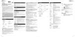
Use the mounting screw holes on the camera to fix the camera to the mounting bracket.
Mounting screw holes
Use UL cable (UL-1015 or equivalent) for 12 VDC or 24 VAC wiring.
J AC Adapter
Use the dedicated AC adapter PA-V17 (optional).
Lens
Important
3x Optical Zoom Lens (Electric Drive)
• You must consult your retailer or provide the mounting bracket yourself.
Protection plate
• A tripod mounting screw (1/4-20 UNC) will fit the fixing screw hole.
Front cover
• Be sure to use a mounting bracket with a mounting screw shorter than 5.5 mm (0.22 in.). Using a
mounting bracket with a mounting screw 5.5 mm (0.22 in.) or longer may damage the camera.
Note
• The camera does not have a power switch. Connecting and disconnecting the LAN cable (PoE power
supply), AC adapter, or external power supply plug turns the power ON and OFF, respectively.
• When the camera needs to be rebooted, perform the reboot operation from the camera setting page
(see “Maintenance” in “Setting Page” of the “VB-M700F/VB-M600D/VB-M600VE Operation Guide”).
Power connection terminal
Example installations
Using a ceiling mounting bracket
24
Conductor diameter
MAC Address
1 Mount the camera to the mounting bracket
Mounting screw holes
Recommended Power Cables for VB-M700F [Reference]
Part Names
2 Connect the cables to the camera
100BT LAN connector
Using a wall mounting bracket
100Base-TX support
PoE power supply (IEEE802.3af compliant)
Connect the LAN cable.
If an AC adapter PA-V17 (optional) or external power supply is used, connect the power
connector to the camera.
Connect cables to the external device I/O terminals and audio input/output terminals as
necessary.
Audio output terminal (LINE OUT)
J External Device Input Terminals (IN1, IN2)
LED
External device input terminals consist of two sets (IN1, IN2) of two terminals, with the negative
terminal connected to the camera interior GND. Connect two cables to the positive and negative
terminals. When electrical continuity or insulation is created between the terminals, the viewer will
be notified of either status.
• Off: when [Turn Off] is selected (see “VB-M700F/VB-M600D/VB-M600VE
Operation Guide”, “Installation Conditions” in “Setting Page”)
When installation is complete, use the Camera Angle Setting Tool to check the image on
the camera and manually adjust the camera angle. Zoom and focus can be adjusted with
the Camera Angle Setting Tool (see “Camera Angle Setting Tool” in “VB-M700F/VB-M600D/
VB-M600VE Operation Guide”).
External device I/O terminals consist of two input and output systems each. VB-M700 Viewer
and RM Viewer can be used to check external device input status and control output to an
external device (see “Operating the External Device Output” and “Displaying Event Status” in the
“VB-M700F/VB-M600D/VB-M600VE Operation Guide”).
External Device I/O Terminals
The blue LED light comes on.
• On: when powered on, during reboot, during normal use
3 Set the camera angle
External Device I/O Terminals
* When [Turn Off] is selected, the LED light will come on for several seconds
when the camera is powered on and during reboot.
Important
Reset Switch
• When connecting sensors and switches, connect terminals that are electrically isolated from the
respective power and GND.
Power connector
Turn on the power while pushing this switch using a sharp object.
Continue to push the switch for 5 seconds or more to restore all
factory settings except for the date and time.
• Do not push the external device I/O terminal button with too much force. Doing so may cause the button
to remain pushed-in.
LAN cable
SD card cover
J External Device Output Terminals (OUT1, OUT2)
Audio input terminal (dual LINE IN and MIC IN)
External device output terminals consist of two sets (OUT1, OUT2) of two terminals. The sets
have no polarity. Controls from the viewer can be used to switch between electrical continuity and
insulation from one terminal to the next. Using optical couplers, the output terminals are isolated
from the camera's internal circuit.
2
The load connected to the output terminals should be within the following rating range.
Rating between output terminals:
Internal Connection Diagram
Maximum voltage 50 VDC
+3.3 V
Continuous load current at or below 100 mA
1 kΩ
Note
Connecting the Camera
Using an SD Memory Card
Using Camera Housing
Open the SD card cover as shown in the diagram to insert or remove the SD memory card.
Firmly shut the SD card cover after inserting or removing the SD memory card.
When using the camera mounted in commercial camera housing, remove the camera's protection
plate to reduce the effects of excess reflections within the housing.
• Remove the lock screw on the front cover and remove the front cover and protection plate. Then
return only the front cover to its original position and fix in place with the lock screw.
Power Connection
Power can be supplied to the camera in the three ways described below.
The camera supports PoE functions. Power can be supplied to the camera by using a LAN cable
to connect it to a PoE HUB that conforms to the IEEE 802.3af standard.
• Check with your Canon sales representative for more information about PoE HUB and Midspan
technology.
SD card cover
• Some PoE HUBs allow current limits for each port, but applying limits may interfere with performance. If
using this type of PoE HUB, do not limit the operating current.
• Some PoE HUBs have total consumption current limits for ports, which can interfere with performance
when multiple ports are in use. For more information, check the instruction guide for your PoE HUB.
Protection plate
Front cover
Push the SD memory card as far as possible into the SD card slot.
Removing the card
Push the SD memory card in all the way until the card slightly pops out. Pinch the card and
remove.
• When reattaching the protection plate, face the side with the cutout toward the lens.
Important
• Make sure the SD memory card isn't write-protected.
• When using an SD memory card with the camera for the first time, it is recommended to format the card
after inserting it into the camera (see “Memory Card” in “Setting Page” in the “VB-M700F/VB-M600D/
VB-M600VE Operation Guide”).
• Insert the SD memory card before installing the camera.
+
External device Output terminal
IN1, IN2
0.1 µF
External device
Output terminal
OUT1, OUT2
Audio Input/Output Terminals
Each audio input/output terminal has one input system and one output system.
Connecting the camera to an audio input/output device such as a microphone or a speaker with
an amplifier allows you to send/receive audio through the viewer.
SD card slot
Inserting the card
10 kΩ
J PoE (Power over Ethernet)
Important
Lock screw
Adaptive wiring for external device cables
Solid conductor AWG: No. 28 - 22
Conductor size: Φ 0.32 - Φ 0.65 mm (Φ 0.013 - Φ 0.026 in.)
Cable strip should be approx. 8 - 9 mm (0.31 - 0.35 in.)
Internal controller
10 kΩ
• Use a category 5 or higher cable 100 m (328 ft.) or less in length for the LAN cable that connects the
camera and the PoE HUB.
• When the camera is connected to a switching HUB, changing the connection while the camera is
operating may cause the HUB learning function to interfere with communication. Do not change the
connection when the camera is operating.
• The camera can also be connected to an AC adapter (optional) while receiving power from a PoE
HUB. In such cases, the PoE power supply is given priority, and the camera does not use the power
supply from the AC adapter (optional). When the PoE power supply is disconnected, power is supplied
automatically from the AC adapter (optional). Midspan (a LAN cable power supply device) is a device
that, like a PoE HUB, supplies power to the camera via a LAN cable.
J Audio Input Dual LINE IN/MIC IN (monaural input)
Although the camera has a single audio input system, it supports two types of microphone input:
LINE IN and MIC IN. Before using the audio input, change the [Audio Input] on the Setting Page
(see “Audio Input” in the “VB-M700F/VB-M600D/VB-M600VE Operation Guide”). LINE IN is
selected by default.
Input terminal: Φ 3.5 mm (Φ 0.14 in.) mini-jack (monaural)
• Dynamic MIC IN
Input impedance: 1.75 kΩ ± 20%
* Supported microphones: Output impedance: 400 Ω - 600 Ω
• Condenser MIC IN
Input impedance (microphone bias resistance): 2.2 kΩ ± 20%
Microphone power supply: plug-in power (voltage: 1.8 V)
* Supported microphones: Condenser microphones with plug-in power support
• LINE IN
Input level: Max. 1 Vp-p
* Use a microphone with an amplifier.
J External Power Supply
J Audio Output Terminal LINE OUT (monaural output)
12 VDC or 24 VAC input can be used.
Connect the bundled power connector as shown below.
Connect the camera to a speaker with an amplifier. Audio can be sent to the speaker from RM
Viewer.
Output terminal: Φ 3.5 mm (Φ 0.14 in.) mini-jack (monaural)
Output level: Max. 1 Vp-p
* Use a speaker with an amplifier.
Screwdriver
Tightening torque: 0.2 N·m (max)
For 12 VDC and 24 VAC input, use a power supply insulated
from 100 VAC.
12 VDC can be connected in a non-polar configuration.
Strip
Cutout
Important
Approx. 4 to 6 mm
(0.16 to 0.24 in.)
Power connector
(bundled)
• The power supply should be within the following voltage range.
• 24 VAC: Voltage fluctuation within 10% of 24 VAC (50 Hz or 60 Hz
± 0.5 Hz or less)
Current supply capacity of at least 1.0 A per camera
Important
• Using incorrect settings for [Audio Input] may damage the camera and/or microphone. Be sure to
configure the settings correctly.
• Microphone characteristics may affect volume and sound quality.
• Use RM Viewer to send audio to the speaker. VB-M700 Viewer cannot be used to send audio.
• 12 VDC: Voltage fluctuation within 10% of 12 VDC
Current supply capacity of at least 1.5 A per camera
• Images and audio do not always synchronize properly.
• When using a 12-VDC battery power supply, be sure to connect
resistors of at least 0.5 - 1.0 Ω/20 W in series to the power line.
• Images and audio can be distributed to up to 30 clients. However, audio may be interrupted when
distributing to many clients.
• For an external power supply, use a double-insulated device.
• Audio may be interrupted when using antivirus software.
• Audio may be interrupted depending on PC characteristics and network environment.
• Connecting and disconnecting the LAN cable interrupts the audio. Use the viewer to reconnect.
VBM700IG_E.indd 2
2011/06/16 13:13:47