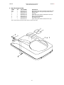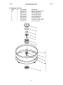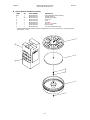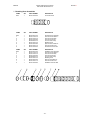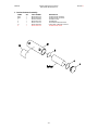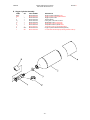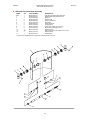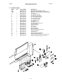
1
Biopak 240S
Benchman Instruction Manual
Biomarine Incorporated
456 Creamery Way
Exton, PA 19341 USA
Phone: (610) 524-8800
Fax: (610) 524-8807
Email: NeutronicsInc.com
Document: A46D030, Revision: K
Part Number: B5-06-6240-01-0
A46D030
Biopak 240S Benchman Manual
Part Number B5-06-6240-01-0
Revision:K
Table of Contents
Subject
Page
NIOSH Approval Label
4
I.
Cautions and Limitations
5
II.
S. Special or Critical User’s Instructions
5
III.
Theory of Biopak Operation
7
A. Biopak Description
B. Breathing Loop
C. High Pressure Plumbing
7
9
10
D. Low Pressure Plumbing
11
Turn-Around Maintenance Procedure
12
A. Turn-Around Maintenance Tag
B. Biopak Disassembly
C. Washing and Disinfecting
12
12
13
D. Oxygen Cylinder Charging
E. Coolant Canister Charging
F. Biopak Re-Assembly
14
15
16
G. Flow Test
H. Carbon Dioxide Absorbent Charging and Installation
I. Facepiece Concerns
16
17
18
J.
18
IV.
V.
Final Re-Assembly
Periodic Long-Term Maintenance
19
A. Visual Inspection
B. High Pressure Leak Testing
C. Low Pressure Leak Testing
19
19
20
D. Flow Testing
E. Optional Facepiece Fit Testing
20
21
General Service Procedures
22
A. Scheduled Component Replacement
B. System Lubrication
C. Oxygen Cylinder
22
23
24
D. Regulator Assembly
E. Bypass Valve Assembly
F. Alarm Whistle Assembly
24
25
26
G. Flow Restrictor Assembly
H. Breathing Chamber Assembly
I. Harness and Straps
27
28
31
J. Facepiece Assembly
K. Factory Service and Training
33
36
VII.
Troubleshooting Guide
37
VIII.
Biopak Specifications
41
VI.
-2-
A46D030
Biopak 240S Benchman Manual
Part Number B5-06-6240-01-0
Revision:K
IX.
Warranty Statement
42
X.
Illustrated Parts Lists
44
A. Top Assembly
B. Lower Housing Assembly
C. Upper Housing Assembly
44
46
47
D. Pneumatic Assembly
E. Bypass Valve Assembly
F. Breathing Chamber Assembly
48
49
50
G. Diaphragm Assembly
H. Carbon Dioxide Scrubber Assembly
I. Breathing Hose Assemblies
51
52
53
J. Coolant Canister Assembly
K. Oxygen Cylinder Assembly
L. Scott-Style Facepiece Assembly
54
55
56
M. AGA-Style Facepiece Assembly
N. AGA-Style Facepiece Wiper Assembly
O. Tool Kit Assembly
57
59
60
P. Miscellaneous Supplies
61
Appendix A: Maintenance Log Sheet
62
Appendix B: Material Hazards, Handling and First Aid
63
-3-
Revision:K
D46A011-01
Exhalation Breathing Hose
D46A019-03
Inhalation Breathing Hose
D46A019-02
Connection Breathing Hose
D46A019-01
Carbon Dioxide Scrubber Lid
D46A018
Carbon Dioxide Absorbent
LimePak
Alternate Oxygen Cylinder
Assembly
Ultra-Lite Black/White
C17A003-03
Ultra-Lite Green
C17A003-04
Coolant Device
B17A013
CoolTube
Alternate Carbon Dioxide
Scrubber
D17A038
D46A010
Factory Packed
300-887 G2
Standard
300-887 G1
without Anti-Anoxia
D46A006-02
with Anti-Anoxia
D46A006-01
X
X
X
X
X
X
X
X
with Rotational Latch
D46A008-02
with Fleixble Latch
D46A008-01
Alternate Lower Housing
Assembly
with Rotational Latch
D46A009-02
with Fleixble Latch
D46A009-01
2 CAUTIONS AND WARNINGS
PD-Pressure demand
1 PROTECTION
X
240-MIN/3000 PSIG/SC/PD
13F-466
PROTECTION1
TC#
-4-
SC-Self-contained
X
Alternate Upper Housing
Assembly
X
D46A007
X
Pneumatic Assembly
X
Alternate Center Section
S-Special or critical User's Instructions and/or specific use limitations apply. Refer to User's Instructions before donning.
Scott-Style Standard-Small
O-Refer to User's Instructions, and/or maintenance manuals for information on use and maintenance of these respirators.
D46A011-02
N-Never substitute, modify, add, or omit parts. Use only exact replacement parts in the configuration as specified by the manufacturer.
D46A011-03
Scott-Style Standard-Large
M-All approved respirators shall be selected, fitted, used and maintained in accordance with MSHA, OSHA and other applicable regulations.
Scott-Style Standard-Xlarge
J-Failure to properly use and maintain this product could result in injury or death.
D46A011-04
X
JMNOS
Scott-Style Wipered-Small
X
D46A011-05
X
D46A011-06
Scott-Style Wipered-Large
X
Scott-Style Wipered-Xlarge
X
400-471 G2
X
AGA-Style w/ Microphone
X
400-471 G11
X
400-471 G12
AGA-Style w/ Speaking Diaphragm
X
AGA-Style w/ Voice Amplifer
X
400-471 G13
X
AGA-Style w/ Wiper
X
B46D060
X
B46D061
Facepiece Eyeglass Kit
X
Alternate Facepiece Assemblies
RESPIRATOR COMPONENTS
Facepiece Voice Amplifier
Coolant Canister Assembly
THESE RESPIRATORS ARE APPROVED IN THE FOLLOWING CONFIGURATIONS:
CLOSED-CIRCUIT, PRESSURE DEMAND, ENTRY AND ESCAPE, SELF-CONTAINED BREATHING APPARATUS
Biopak 240S
PHONE: (610) 524-8800, FAX: (610) 524-8807, EMAIL: NeutronicsInc.com
BIOMARINE INCORPORATED
456 CREAMERY WAY, EXTON, PA 19341 USA
B17D190
X
Cylinder Knob Extender
X
201-228 G1
X
Anti-Fog Agent
X
Cautions and Limitations2
Accessories
A46D054
[REV F]
03/28/2003
Biopak 240S Benchman Manual
Part Number B5-06-6240-01-0
X
A46D030
A46D030
Biopak 240S Benchman Manual
Part Number B5-06-6240-01-0
Revision:K
I. Cautions and Limitations
♦
Failure to properly use and maintain this product could result in injury or death.
♦
All approved respirators shall be selected, fitted, used and maintained in accordance with
MSHA, OSHA and other applicable regulations.
♦
Never substitute, modify, add or omit parts. Use only exact replacement parts in the
configuration as specified by the manufacturer.
♦
Refer to User’s Instructions and/or maintenance manuals for information on use and
maintenance of these respirators.
♦
Special or critical User’s Instructions and/or specific use limitations apply. Refer to User’s
Instructions before donning.
II. S. Special or Critical User’s Instructions
♦
All users of the Self-Contained Breathing Apparatus (SCBA) must be trained by qualified
instructors in donning, operation, inspection and emergency use procedures.
♦
All repairs beyond the scope of this manual must be performed by Biomarine Incorporated or
a qualified Biomarine Service Center.
♦
Prior to using the SCBA it must be determined that user is medically fit. The following are
some, but not all, medical and psychological conditions that could limit the use of the SCBA:
!
Emphysema
!
Chronic Obstructive Pulmonary Disease
!
Bronchial Asthma
!
X-ray evidence of Pneumonia
!
Evidence of reduce pulmonary function
!
Coronary Artery Disease
!
Severe or progressive hypertension
!
Epilepsy-Grand Mal or Petit Mal
!
Pernicious Anemia
!
Diabetes-Insidious or Mellitus
!
Breathing difficulties when wearing a SCBA
!
Claustrophobia or anxiety when wearing a SCBA
!
Abnormal or ruptured ear drum
♦
Compressed Oxygen Hazard: Always handle oxygen cylinders with care to prevent
rupture. Do not allow oil, grease or other combustible materials to come in contact with the
cylinder or cylinder valve to prevent ignition. Do not open the cylinder valve in the presence
of open flame or sparks to prevent ignition. Failure to heed this warning may result in
personal injury or death due to sudden release of high-pressure oxygen and/or fire.
♦
Oxidizing Agent Hazard: Oxygen is a non-flammable gas; however, it will enhance the
combustion of other materials. Oxygen enrichment will decrease the energy required for the
ignition of materials. In an oxygen rich environment, oxygen concentration exceeding 23% by
volume at sea level, materials that normally will not burn in air may burn; and, materials that
do burn in air will burn more vigorously and at a higher temperature. Oxygen will not cause
materials to ignite unless there is an ignition source present.
-5-
A46D030
Biopak 240S Benchman Manual
Part Number B5-06-6240-01-0
Revision:K
♦
This SCBA is approved for respiratory protection during entry into and escape from oxygen
deficient atmospheric gases and vapors at temperatures above +15oF.
♦
This SCBA is approved only when the oxygen cylinder is fully charged with compressed
oxygen meeting U.S.P. specifications.
♦
The oxygen cylinder shall meet applicable DOT specifications and shall be marked
“COMPRESSED BREATHING OXYGEN”.
♦
Do not use this apparatus near open flames or in high radiant heat.
♦
After each use of this apparatus, a fully charged breathing gas container and a recharge of
carbon dioxide absorbent shall be installed.
♦
Thorough cleaning and disinfecting of the facepiece, breathing tube and breathing bag must
be done in accordance with the manufacturer’s instructions.
♦
Use with adequate skin protection when worn in gases or vapors that poison by skin
absorption (for example hydrocyanic acid gas).
♦
A good facepiece seal is important since facepiece leakage will severely reduce service time.
♦
Use of pure oxygen or enriched air increases the flammability and lowers the ignition
temperature of most materials.
♦
Special handling procedures shall be instituted when utilizing the carbon dioxide scrubber
material, LimePak, and the anti-fog facepiece solution. Refer to Appendix B of this manual
for details.
-6-
A46D030
Biopak 240S Benchman Manual
Part Number B5-06-6240-01-0
Revision:K
III. Theory of Biopak Operation
A. Biopak Description
The Biopak 240S is a four-hour, self-contained, closed-circuit, positive-pressure breathing
apparatus that is NIOSH approved for entry into and escape from oxygen deficient
atmospheres. The apparatus differs from open-circuit devices in that all breathing air is
recycled and confined within the device itself. Only during periods of high volumetric
exhalation will any breathing atmosphere be vented into the surround ambient atmosphere.
Breathing air is continually recycled in the device with exhaled carbon dioxide from the user
captured by means of an absorbent media. Breathing gas volumes lost through the
absorption of carbon dioxide are directly replaced with a constant bleed of 100% oxygen
from an on-board supply. Breathing is gas continually cooled through the use of a frozen gel
to maintain user comfort throughout the four-hour duration of the apparatus.
The apparatus is supplied with a full facepiece and is housed in a clamshell type backpack
housing. Hoses extend through the top of the housing to connect on either side of the
facepiece to provide full mobility and viewing angles to the user.
The Biopak consists a three main sub-systems, the Breathing Loop, The High Pressure
Plumbing and the Low Pressure Plumbing. The Breathing Loop consists of all components
that are in direct contact with the breathing atmosphere to the user. High Pressure Plumbing
components work to reduce the high pressure of the on-board oxygen supply to acceptable
levels for use in breathing. Low Pressure Plumbing components deliver the reduced
pressure oxygen into the Breathing Loop. Figure 1 provides a graphical representation of
the complete respirator system.
Alarm features are provided to warn the user when oxygen stores are either running out or
have not been activated. A chest-mounted pressure gauge will provide the user with a
visual real-time indication of remaining oxygen stores and will provide a visual alarm when
only 1-hour of oxygen supply remains. An alarm whistle will provide a 92dB sounding when
remaining oxygen stores will provide one final hour of operation. An anti-anoxia feature will
prevent use of the respirator whenever oxygen stores have not been installed or activated by
the user.
A counter-lung and spring arrangement is utilized to maintain positive pressure in the device
during the exhalation and inhalation cycles of the respiration. The positive pressure will
insure that the entire breathing loop of the respirator is greater than the external ambient
pressure. This will insure that leakage, such as around the facepiece seal, is out of rather
than into the respirator. Outward leakage will lessen the potential for the migration of
harmful external agents into the breathing atmosphere. The Biopak 240S has a Protection
Factor greater than 20,000 that has been derived from a Quantitative Fit Test. In the
Quantitative Fit Test the rebreather is exposed to an ambient atmosphere heavily laden with
particle contamination. A measure of the particle concentration outside of the respirator is
divided by a measure of the particle concentration in the respirator facepiece to establish the
Protection Factor.
The Biopak has been utilized in mine rescue, tunneling, hazardous material remediation, fire
fighting, chemical and biological warfare and numerous other applications. Anywhere a
potential exists for an oxygen deficient atmosphere or an atmosphere that may contain a
human health hazard agent can be considered an application of the Biopak.
-7-
A46D030
Biopak 240S Benchman Manual
Part Number B5-06-6240-01-0
-8-
Revision:K
A46D030
Biopak 240S Benchman Manual
Part Number B5-06-6240-01-0
Revision:K
B. Breathing Loop
The breathing loop consists of all components that are direct contact with the breathing
atmosphere. Referring to Figure 1, the breathing loop includes the facepiece, the exhalation
hose, the breathing chamber, the coolant canister and the inhalation hose. These
components all work to provide a positive pressure breathing atmosphere of 90-100% by
volume oxygen and 90-100% relative humidity.
Facepiece: The facepiece will fit directly onto the face of the user and will provide coverage
from under the chin to the forehead. Check valves are provided in the facepiece to force
breathing atmosphere flow in the preferred direction. The check valves will also insure that
the breathing atmosphere does not hang-up or remain in the facepiece, which could result
carbon dioxide build-up and poisoning. The facepiece is available in multiple sizes and
styles (Scott, AGA and Drager) to provide the best fit to the user. Facepiece fit is critical in
maintaining the positive pressure seal and conserving the duration of the respirator.
Standard facepieces are supplied with speaking diaphragms, an anti-fog lens insert and
nosecup. Optional features include lens wipers, spectacle mounting kits, voice amplification
kits and voice communication systems.
Exhalation Breathing Hose: The exhalation breathing hose is a flexible hose that will
transfer user exhalation from the mask and into the breathing chamber.
Breathing Chamber: The breathing chamber provides carbon dioxide absorption,
maintains system positive pressure, maintains system volumetric control through venting
and adding and provides anti-anoxia protection. The specific components of the breathing
chamber are as follows:
Anti-Anoxia Valve: The anti-anoxia valve, an optional device, is simply a plug that will
restrict the exhalation hose connection to the breathing chamber in the event oxygen
stores have not been installed or activated in the respirator. Once the oxygen stores
have been activated, a pneumatic cylinder will withdraw the plug from the exhalation
hose port. When the plug is in the exhalation hose port the resulting breathing resistance
will make it impossible for the user to breath the respirator thus providing a direct
indication of no oxygen pressure.
Diaphragm and Diaphragm Spring: The diaphragm and spring combine to form the
counter-lung. The counter-lung will react in an opposite direction from the user lungs and
in combination with the spring will maintain positive pressure within the respirator.
Vent Valve: The vent valve is located on the diaphragm and is mechanically actuated
whenever the exhalation of the user exceeds the tidal volume of the respirator. Once the
respirator tidal volume has been exceeded, the vent valve will be forced open to release
excess gas. This will insure that exhalation breathing resistances do not build up and
cause user discomfort. The valve is a two-stage device providing dual seals for added
protection.
Demand Valve: The demand valve is a mechanically actuated valve located at the
upper end of the diaphragm inhalation travel stroke. In periods of heavy loads the user
requirements may exceed those of the standard respirator function. The demand valve
will open to admit additional flow of oxygen into the breathing loop. This device insures
that the respirator will supply the user with additional oxygen as required and will also
insure against the respirator going into a negative pressure situation during inhalation.
-9-
A46D030
Biopak 240S Benchman Manual
Part Number B5-06-6240-01-0
Revision:K
Breathing Chamber (continued)
Flow Restrictor: The flow restrictor admits a constant flow of oxygen directly into the
breathing loop to replace volumes lost through user consumption and carbon dioxide
absorption. Oxygen will continually flow from the restrictor at 1.78 lpm, which is 4-9 times
greater than the metabolic consumption of oxygen by a human at rest. Metabolic
consumption rates of oxygen by human subjects can be characterized as listed below.
Body at Rest
Light Work Load
Moderate Work Load
Heavy Work Load
Extremely Heavy Work Load
0.2 to 0.5 lpm
0.8 to 1.0 lpm
1.0 to 1.5 lpm
1.5 to 2.0 lpm
2.0 to 3.0+ lpm
Carbon Dioxide Scrubber Canister: The carbon dioxide scrubber canister will remove
user-exhaled carbon dioxide through a chemical reaction. It is essential to remove the
carbon dioxide from the breathing loop as it will become toxic to the user over time and
will lead to poisoning. Carbon dioxide is a byproduct of the user metabolic consumption
of oxygen. The chemical reaction of the carbon dioxide absorption will release heat and
moisture into the breathing loop and transform the scrubbing media into calcium
carbonate as shown by the reaction below.
CO2 + Ca(OH)2
Carbon Dioxide + Calcium Hydroxide
Y CaCO
Y
3
+ H2O
Calcium Carbonate + Water
Connection Hose: The short, flexible connection hose supplies warm, wet and carbon
dioxide-free gas from the breathing chamber to the coolant canister.
Coolant Canister: The coolant canister is a housing that contains a frozen gel tube or pack.
Breathing gas from the connection hose will enter the canister at approximately 120oF and
100% moisture saturation. The frozen gel will absorb much of the breathing gas heat to
maintain the gas temperature and dew point below 90oF (note that the NIOSH limit is 95oF).
Inhalation Breathing Hose: The inhalation breathing hose is a flexible hose that will
transfer carbon dioxide-free, cooled and condensed breathing air from the coolant canister
into the inhalation port of the facepiece.
C.
High Pressure Plumbing
The high-pressure plumbing includes all components that are exposed to the high-pressure
oxygen stores. Referring to Figure 1 this includes the oxygen cylinder, oxygen cylinder
pressure gauge, oxygen cylinder valve, pressure regulator and chest mounted pressure
gauge. These components serve to reduce the stored oxygen high pressure to a usable
pressure level, control the actuation of the oxygen stores and indicate the amount of
remaining oxygen stores.
Oxygen Cylinder: The oxygen cylinder is a lightweight, carbon composite wrapped,
aluminum lined, DOT approved pressure vessel that will contain the store of high-pressure
oxygen in the respirator. The cylinder will hold 21 cubic feet of oxygen compressed to 3000
psi when fully charged. This amount of oxygen will support the full four-hour duration of the
respirator. The cylinder shall only be charged with U.S.P. medical grade 100% oxygen and
requires hydrostatic testing every five (5) years according to CGA pamphlet C-6.2. The
cylinder is removable to permit recharging either in-house or by a third party.
Oxygen Cylinder Valve: The oxygen cylinder valve is attached directly to the oxygen
cylinder and provides a mechanism for manually opening and closing the oxygen cylinder to
the high-pressure plumbing system.
Oxygen Cylinder Pressure Gauge: The oxygen cylinder pressure gauge is connected
directly to the oxygen cylinder and will provide a visual indication of the amount of oxygen
- 10 -
A46D030
Biopak 240S Benchman Manual
Part Number B5-06-6240-01-0
Revision:K
stored in the cylinder. The gauge will indicate the internal pressure of the cylinder
regardless of the position of the oxygen cylinder valve. This provides constant indication of
cylinder fill conditions.
Pressure Regulator: The pressure regulator consists of a pressure reducing mechanism
and a 2-pin yoke. The pressure regulating mechanism will reduce the high pressure of the
oxygen cylinder to approximately 260 psig for delivery into the low pressure plumbing
system. The two-pin yoke consists of a standard CGA oxygen valve connection format and
a threaded handle to lock the valve of the oxygen cylinder into position onto the pressure
regulator.
Chest Mounted Pressure Gauge: The chest mounted pressure gauge mounts on the
harness of the respirator and connects directly to the high pressure of the oxygen cylinder to
provide the user with a real-time visual indication of remaining oxygen stores during use.
Connection of the gauge to the oxygen cylinder is made via an armored plumbing line to
protect it from damage during respirator use. A flow restrictor is employed between the
gauge and the cylinder to prevent the sudden release of oxygen stores in the event the
connecting line becomes severed. The gauge provides a direct indication of pressure
remaining in the oxygen cylinder that can be translated into remaining respirator use time as
listed below. A red area on the gauge dial indicates to the user when approximately onehour of oxygen stores remain.
Gauge Reading, psi
3000
2250
1500
750
Remaining Use Time, Hours
4
3
2
1
D. Low Pressure Plumbing
The low-pressure plumbing consists of all components that deliver the reduced pressure
oxygen stores into the breathing loop and provide audible alarm features. Referring to
Figure 1 this will include the bypass valve, alarm whistle and associated small diameter
tubing.
Bypass Valve: The bypass valve is a manually operated pushbutton located on the exterior
of the respirator housing and will provide unrestricted flow of oxygen into the breathing loop
when depressed. The valve is intended for emergency uses only as described in the User
Instruction Manual.
Alarm Whistle: The alarm whistle will provide a 92 dB audible signal for 45-60 seconds
whenever remaining oxygen stores are 25% of full capacity. The alarm is a one-time signal
that signals the user when approximately one-hour of oxygen remains. The alarm is situated
between the low pressure and high-pressure plumbing components and functions on the
differential pressure between the two systems.
Associated Plumbing: The associated plumbing of the low-pressure system is 1/8”
diameter metal and plastic tubing that will connect the reduced pressure oxygen to the
breathing loop and the alarm whistle.
- 11 -
A46D030
Biopak 240S Benchman Manual
Part Number B5-06-6240-01-0
Revision:K
IV. Turn-Around Maintenance Procedure
NOTE: Turn-Around Maintenance procedures should be preformed as soon as
possible after each use of the Biopak to provide for immediate reuse and
to prevent the growth of biological organisms in non-disinfected
equipment.
A. Turn-Around Maintenance Tag
The Turn-Around Maintenance Tag provides an indication of completed procedures and
inspections for user verification before subsequent Biopak uses. Tags are supplied in bulk
with each shipment of carbon dioxide absorbent and should be utilized throughout the
procedures outlined in this section of the manual. Without the completed tag in place on the
Biopak, the user will not know for certain that the Biopak is ready for use.
B. Biopak Disassembly
1. Use a sponge and mild soap to wipe clean the entire exterior of the Biopak and harness.
Wipe dry or allow to air dry.
2. Remove the upper housing from the Biopak by disconnecting the two latches to release
and swing the housing up so that it can be lifted off of the hinge plates.
3. Disconnect the hoses from the facepiece by unthreading the hose connectors.
Disconnect the connection and exhalation hoses from the breathing chamber by
unthreading the worm gear clamps. Remove the coolant canister from the Biopak by
disconnecting the Velcro straps. Remove the end cap from the coolant canister by
rotating in a clockwise direction and pulling it straight out of the end of the housing.
Remove the coolant device from inside the canister. Submit the coolant canister with
hoses connected and the coolant device to the washing and disinfecting procedure.
Retain the worm gear clamps for reuse.
4. Inspect the anti-fog lens of the facepiece to verify that the perimeter seal is consistent
and does not contain voids. Re-burnish the sealing edges if required.
5. Remove the stainless steel cover from the breathing chamber as outlined below.
a) Slide the snap latches of the cover to disengage them from the studs.
b) Pull up on the lip of the cover with the fingers while pushing down on the breathing
hose stubs of the breathing chamber with thumbs to remove the cover. Submit the
cover to the washing and disinfecting procedure.
CAUTION: Do not use a screwdriver or any other instrument or tool to pry the
cover away from the breathing chamber. Such action will risk damage
to the top edge of the breathing chamber as well as possibly damage
the breathing chamber o-ring seals.
6. Lift the carbon dioxide scrubbing canister out of the breathing chamber by lifting on the
canister edge with the fingers and pressing down on the breathing chamber rim with the
thumbs.
CAUTION: Do not use a screwdriver or any other instrument or tool to pry the
canister out of the breathing chamber. Such action will risk damage to
the top edge of the breathing chamber as well as possibly damage the
breathing chamber o-ring seals.
- 12 -
A46D030
Biopak 240S Benchman Manual
Part Number B5-06-6240-01-0
Revision:K
7. Remove the carbon dioxide scrubbing canister from the Biopak work area and remove
the top cover by pushing the latch away from the center stud. It is best to remove the
top cover over a waste bin since the scrubbing media is in granular form and may spill
out. Submit the cover to the washing and disinfecting procedure.
8. Remove the foam pad from the scrubber and dump the internal granular contents into a
suitable waste bin. The granular scrubbing media is spent soda lime that is has been
converted to limestone and is safe to dispose in regular trash. Submit the canister body
and foam pad to the washing and disinfecting procedure.
CAUTION: Always wear rubber gloves and safety glasses when working with
soda lime. Reference Appendix B for details on the hazards of soda
lime, proper handling and first aid measures.
9. Remove the oxygen cylinder from the Biopak by rotating the regulator yoke handle in a
counterclockwise direction to loosen the connection. Guide the cylinder up off of the
center post and pins and out of the yoke. Remove the sealing washer that seals the
cylinder valve to the yoke and retain for reuse. Submit the oxygen cylinder to the
oxygen cylinder filling procedure. It is acceptable to leave the oxygen cylinder in place
during the duration of the washing and disinfecting procedure.
WARNING: Before removing the oxygen cylinder, verify that the cylinder valve is
closed, that the chest mounted pressure gauge reads 0 psi, and
depress the bypass valve to relieve any internal pressure.
10. Disconnect the two nylon plumbing lines to the breathing chamber disconnecting the
quick disconnect fittings at the chamber. Remove the breathing chamber from the
Biopak by disengaging the four pushpins located at the 3, 6, 9 and 12 o’clock positions
around the chamber. Pressing the center button of the pin down while pulling the entire
pin up disengages the pins. Retain the pins for future reuse and submit the breathing
chamber to the washing and disinfecting procedure.
C. Washing and Disinfecting
1. Complete the Biopak disassembly procedure before washing and disinfecting.
2. Prepare a disinfecting solution by cutting open the disinfectant agent packet, part
number B6-02-5000-42-0, and pouring the contents into clean, warm water. Add one
packet per each gallon of water.
CAUTION: Do not substitute any other disinfectant agent. Other agents may
contain alcohol or chlorine that can deteriorate facepiece lens and
rubber components.
3. Place the facepiece, all coolant canister parts, the breathing chamber lid and all the
hoses into the disinfecting solution for a minimum of ten minutes. Rinse the components
thoroughly with the solution insuring that all surfaces have become wetted. Be sure to
introduce the solution into the internal volume of the breathing chamber.
NOTE: Do not wash and disinfect the carbon dioxide scrubber components until
after washing all other components to avoid contact of absorbent granules.
4. Cover the demand housing, located in the center of the breathing chamber, with a finger
cot; or, remove the restrictor fitting from the top of the demand housing and install the
- 13 -
A46D030
Biopak 240S Benchman Manual
Part Number B5-06-6240-01-0
Revision:K
demand housing wash plug, supplied with the tool kit, until it fully bottoms out on the top
of the demand housing.
5. Pour disinfectant solution into the tube stubs of the breathing chamber. Vigorously
shake the breathing chamber with the tube stub end blocked to spread the solution
throughout the chamber. Allow all internal breathing chamber surfaces to remain wetted
with the cleaning solution for a minimum of ten-minutes.
CAUTION: It is advised not to totally submerge the breathing chamber into the
disinfectant solution to avoid contact of the solution with the demand
housing flow restrictor. Contact of the solution with the flow restrictor
may cause restrictor clogging.
6. Remove the components from the solution and rinse several times in clean, fresh water.
Set the rinsed components aside to air dry; or, dry the components with a hair drier set
for cool temperature.
7. Place the carbon dioxide scrubber canister body, lid and pad into the solution for a
minimum of ten minutes. Rinse the components thoroughly with the solution to insure
that all surfaces become wetted.
8. Remove the carbon dioxide scrubber components from the solution and rinse several
times in clean, fresh water. Allow the components to air-dry or dry them with a hair drier
set for cool temperature.
9. Remove the finger cot from the breathing chamber demand housing; or, remove the
demand housing wash plug and re-install the restrictor fitting to the top of the demand
housing.
10. Check the “WASHING/DISINFECTING” box on the Turn-Around Maintenance Tag.
D. Oxygen Cylinder Charging
1. For Charging of the Oxygen Cylinder by Third Parties: Verify that the cylinder valve
and seat are clean and cover with a clear plastic bag. Secure the bag with a rubber
band or tie. Supply the cylinder to the third party filling vendor with instructions to fill
between 2700 and 3000 psig, as read by the cylinder gauge after the cylinder has
cooled to 70oF, with U.S.P. medical grade oxygen.
2. For In-House Charging: Follow the guidelines outlined below.
a) The filling area should be completely free of any grease or oil products. If the filling
is done in a small confined area, adequate ventilation should be provided to prevent
the build up of oxygen and the formation of an oxygen rich atmosphere.
b) Only U.S.P medical grade oxygen is to be used to fill Biopak oxygen cylinders.
Other grades of oxygen may contain impurities and excess moisture that can affect
the cylinder as well as the plumbing in the Biopak.
c) To further protect the oxygen supply from possible contamination from moisture or
dust, it is recommended that each booster pump be equipped with a filter/drier
assembly installed on the gas inlet side of the booster pump. The filter shall be
serviced at regular intervals as required.
d) Before filling any cylinder visually inspect the cylinder under a bright light for signs
of physical damage and the accumulation of contaminants such as dirt, lint, grease
or oil. Clean all contaminants from the cylinder before proceeding with filling. Cuts
in the outer wrapping of the cylinder require hydrostatic testing at a test facility as
per CGA pamphlet C-6.2.
- 14 -
A46D030
Biopak 240S Benchman Manual
Part Number B5-06-6240-01-0
Revision:K
e) Before filling any cylinder inspect the hydrostatic test date stamped on the cylinder.
If the test date is over five (5) years old the cylinder may not be refilled. Have the
cylinder hydrostatically tested by an approved test facility or Biomarine as per CGA
pamphlet C-6.2 before filling.
f)
Make a special effort to prevent cylinders from being drained below 500 psig, as
indicated by the cylinder pressure gauge, at all times to reduce the possibility of
external contamination migration into the cylinder.
g) Oxygen cylinders that have pressure gauge readings of 0 psig must be purged and
pulled into a vacuum to remove all traces of moisture before filling. It is suggested
that these cylinders be returned to Biomarine to insure proper purging and vacuum
application.
h) Prior to connecting the cylinder to the refill pump the cylinder valve should be briefly
opened to purge the valve seat of accumulated dust and/or moisture. Do not direct
the valve opening towards the face or skin when opening.
i)
Oxygen cylinders should be filed and stored at ambient temperatures maintained at
70oF. Filling a cylinder at high temperatures can result in final fill levels several
hundred psig below the target pressure once the cylinder cools. Conversely, filling
the cylinder at low temperatures may result in a final fill pressure of several hundred
psig above the target pressure once the cylinder warms. The variation of oxygen
pressure with temperature is extreme and can result in hazardous conditions.
Therefore it is imperative that the oxygen cylinder storage temperature be
maintained as close as possible to 70oF at all times.
j)
During cylinder filling the temperature of the cylinder will rise in proportion to how
quickly the cylinder is filled. If the booster pump is heavily loaded, the cylinder
temperature will rise and cause increased oxygen expansion and pressure.
Therefore a two-stage process is required to properly fill the oxygen cylinder. After
filling the cylinder to rated service pressure stamped on the cylinder, the cylinder
should be allowed to cool to approximately 70oF. This will normally require a 15-20
minute cool down period if the cylinder is left in 70oF ambient temperatures. The
pressure as indicated on the cylinder pressure gauge will drop during this cool
down period. Once the cylinder has cooled, a second fill stage to the proper fill
pressure can be made.
k) The above guidelines must be followed in order to safely fill the oxygen cylinder.
Oxygen can be a dangerous substance when not properly handled due its oxidation
and flammability enhancement properties. For further details of oxygen cylinder
filling and supply of proper filling equipment, contact the local Biomarine
representative for assistance.
E. Coolant Canister Charging
1. Complete the washing and disinfecting procedure of all coolant canister components
before proceeding with recharging.
2. Place the washed, disinfected and dried GelPak or Cool Tube into a standard freezer for
at least eight (8) hours at a temperature not greater than 15oF (-10oC) and not lower
than –15oF (-26oC). Position the Cool Tube in the freezer in a horizontal position so that
the internal gel mixture is distributed along the center axis of the tube. Lay the GelPak
in the freezer so that all sections of the GelPak are unfolded and flat.
3. Check the “COOLANT CANISTER IN FREEZER” on the Turn-Around Maintenance tag.
- 15 -
A46D030
Biopak 240S Benchman Manual
Part Number B5-06-6240-01-0
Revision:K
F. Biopak Re-Assembly
1. Position the washed, disinfected and dried breathing chamber into position in the lower
housing of the Biopak. Be sure to properly position the diaphragm spring over and
around the vent valve of the breathing chamber during installation. Secure the breathing
chamber into position using the four pushpins. The pins are installed by pressing the
center button of the pin in while pushing the entire pin into position. Pull up on each pin
after installation to verify that it is securely locked into position. Reconnect the two nylon
plumbing lines to the fittings of the breathing chamber by connecting the quick
disconnect fittings at the chamber. Tug on each connection to verify that it is securely
locked into position.
2. Install the end cap onto the open end of the coolant canister by pressing it straight in
and rotating clockwise to engage the locking pins. Install the free end of the short hose
to the breathing chamber hose stub closest to the 3 o’clock position and secure with a
worm gear clamp. Position the coolant canister into the Biopak and secure with the two
Velcro straps. Route the inhalation hose around the left side of the breathing chamber
and out of the housing top left through-hole.
3. Route the exhalation hose, identified by a red band, through the top right housing
through-hole and around the right side of the breathing chamber and over top of the
short hose connecting the center section and coolant canister. Secure the hose to the
remaining hose stub of the breathing chamber and secure with a worm gear clamp.
4. Connect the free ends of the inhalation and exhalation hoses together with a hosecoupling fitting.
5. Verify that the oxygen cylinder-sealing washer is clean and install it onto the center post
of the regulator. Guide a recharged oxygen cylinder, or a charged test cylinder, into the
regulator yoke and seat it onto the center post and pins of the regulator. Tighten the
regulator yoke against the cylinder to secure the connection. Secure the cylinder in the
Biopak with the Velcro strap.
G. Flow Test
1. Slide a test flow meter, part number B6-02-5000-16-0, over the demand valve housing
located in the center of the breathing chamber well.
2. Insert a wooden tongue depressor into one of the breathing chamber slots located
around the chamber rim and press down to move the diaphragm away from contact with
the demand valve. Wedge the tongue depressor in the slot to maintain its position.
Install a second tongue depressor, as per above, into one of the breathing chamber slots
located 180o from the first tongue depressor.
3. Open the oxygen cylinder valve and verify a flow reading on the flow meter of at least
1.6 lpm with the oxygen cylinder at 3000 psig. If the flow meter does not read at least
1.6 lpm reference the Troubleshooting section of this manual.
4. Close the oxygen cylinder valve and remove the flow meter.
5. Remove the two tongue depressors from the breathing chamber slots. Do not use
excessive force to remove the tongue depressors. If a tongue depressor becomes
wedged in the breathing chamber use a second depressor installed into the next slot to
free the wedged depressor.
6. Check the “FLOW TEST” box of the Turn-Around Maintenance Tag.
- 16 -
A46D030
Biopak 240S Benchman Manual
Part Number B5-06-6240-01-0
Revision:K
H. Carbon Dioxide Absorbent Charging and Installation
CAUTION: Always wear rubber gloves and safety glasses when working with
soda lime. Reference Appendix B for details on the hazards of soda
lime, proper handling and first aid measures.
1. Complete the washing and disinfecting procedure of all carbon dioxide scrubber
components before proceeding with recharging.
2. Using a Limepak keg, part number B6-02-5000-32-0, refill the body of the scrubber
canister with absorbent to the fill line indicated on the center post.
3. Shake the canister back and forth on a smooth surface to promote settling of the
absorbent into the canister.
4. Add additional absorbent as required to fill to the indicated level.
WARNING: Do not expose the absorbent material to the ambient atmosphere for
more than a total of one (1) hour during recharging and/or servicing.
Excessive exposure of the absorbent to ambient atmosphere will
reduce the absorbent efficiency.
WARNING: The carbon dioxide absorbent material has a maximum shelf life of
five (5) years when sealed in its container. Once the container seal
has been broken the shelf life of the absorbent is reduced to one (1)
year from the date of opening. Always mark the date of container
opening in the designated location on the container.
5. Inspect the foam pad and verify that it not compressed. Replace any foam pad that is
less than 1/8” thick over the absorbent coverage area or 1/32” on the outside diameter.
Any foam pad that does not overlap the outer edge of the canister body should also be
replaced.
6. Position the foam pad on top of the canister so that the center stud protrudes through
the center hole of the pad and the pad overlaps the outside diameter of the canister
body.
7. Install the scrubber cover onto the top of the foam pad and secure into position by
sliding the snap latch onto the center stud of the canister body.
8. With the cover installed and locked into position, shake the scrubber assembly. If
properly filled there shall be no sounds of absorbent shifting during shaking. The foam
pad should extend through the holes of the cover.
9. Inspect the large o-ring seal located on the inside diameter of the breathing chamber for
nicks, cuts or abrasions according to guidelines set forth in Section VI.B.. Replace the
o-ring if signs of damage are evident. Lightly lubricate the o-ring with Dow-111 o-ring
lubricant.
10. Position the charged carbon dioxide scrubber into the center of the breathing chamber
well and press straight down and into the well until the scrubber bottoms out.
11. Remove and inspect the large o-ring seal located on the outside diameter of the
breathing chamber for nicks, cuts or abrasions according to guidelines set forth in
Section VI.B.. Replace the o-ring if signs of damage are evident. Lightly lubricate the oring with Dow-111 o-ring lubricant and re-install.
12. Position the washed, disinfected and dried breathing chamber cover over the center of
the breathing chamber and press straight down so that the chamber studs protrude
- 17 -
A46D030
Biopak 240S Benchman Manual
Part Number B5-06-6240-01-0
Revision:K
through the cover through-holes. Slide the snap latches of the cover onto the studs to
secure the cover in place.
13. Check the “CARBON DIOXIDE ABSORBENT REPLACEMENT” box on the Turn-Around
Maintenance Tag.
I.
Facepiece Concerns
1. Complete the washing and disinfecting procedure to the facepiece before proceeding.
2. Inspect the facepiece rubber components for signs of wear, cuts, nicks or abrasions.
Replace the facepiece as required.
3. Inspect the perimeter seal of the anti-fog lens. Re-burnish the seal edges if voids or
gaps are evident.
4. Use the anti-fog cloth, part number B6-02-5000-08-0, to apply a heavy coat of anti-fog
agent onto the exposed inside surface of the facepiece lens and/or anti-fog lens. Best
results are gained by storing the facepiece with the anti-fog agent in place and un-buffed
on the lens.
CAUTION: Do not ingest the anti-fog solution or allow the anti-fog solution to
contact the eyes. Refer to Appendix B for handling and first aid
measures.
5. Check the “ANTI-FOG AGENT APPLICATION” box of the Turn-Around Maintenance
Tag.
J. Final Re-Assembly
1. If a test oxygen cylinder has been installed, replace it with a freshly charged oxygen
cylinder. Open the cylinder valve and listen for leaks, the alarm whistle chirping and
verify that the chest-mounted pressure gauge has the same reading as the oxygen
cylinder pressure gauge after 90 seconds. Close the cylinder valve after testing.
a) If leaks are heard try reseating the oxygen cylinder on the regulator and inspect the
sealing washing between the regulator and the cylinder. Replace the washer if
damaged or if leaking persists.
b) If the alarm whistle does not chirp upon opening of the cylinder valve replace the
alarm whistle.
c) If the chest mounted pressure gauge reading is incorrect replace the chestmounted gauge and pressure line.
2. Verify that the oxygen cylinder is securely fastened to the Biopak at the regulator and
with the Velcro strap. Verify that the pressure gauge of the regulator reads between
2700 and 3000 psig. Check the OXYGEN CYLINDER REPLACEMENT” box on the
Turn-Around Maintenance Tag.
3. Reinstall the upper housing to the Biopak and secure into position using the two housing
latches.
4. Sign and date the Turn-Around Maintenance Tag and attach it to the handle of the
oxygen cylinder valve.
5. Place the Biopak in its designated storage location. The Biopak is now ready for reuse.
- 18 -
A46D030
Biopak 240S Benchman Manual
Part Number B5-06-6240-01-0
Revision:K
V. Periodic Long-Term Maintenance
In addition the normal Turn-Around Maintenance, the Biopak should be visually inspected, flow
tested and high and low pressure tested on a monthly basis for units that are in constant use.
Biopaks that are in extended storage may be visually inspected, flow tested and high and low
pressure tested on a quarterly basis provided the following conditions have been met:
•
Biopak is stored in an acceptable environment between 32oF (0oC) and 85oF (30oC) away
from contact with contaminates such as dirt, liquids, etc.
•
Turn-Around Maintenance has been performed after each use in a timely manner.
•
Biopak is stored sealed with all connections tight and the breathing hoses connected
together with the hose-coupling fitting.
NOTE: A properly maintained and sealed Biopak can be stored up to one (1) year
and placed directly into use. Only under circumstances where the Biopak
is to be stored for a 6-12 month period may the Periodic Long-Term
Maintenance schedule be extended to biannually or annually. Periodic
Long-Term Maintenance must be performed on a monthly basis for
Biopaks that have regular (daily, weekly or monthly) use schedules.
Maintenance schedules should be tailored to the use schedule of the
Biopak.
After completing the visual inspection, the flow test, the high pressure testing and the low
pressure testing, sign and date the back of the Turn-Around Maintenance Tag and complete
the Maintenance Log Sheet, reference Appendix A, to maintain a record of scheduled
maintenance.
A. Visual Inspection
1. Remove the upper housing from the Biopak.
2. Visually inspect all components and housings for signs of wear, abuse, damage or loose
connections or parts that may impair the ability of the Biopak to function properly.
3. Repair or replace any component that appears questionable.
4. Replace the upper housing onto the Biopak.
B. High Pressure Leak Testing
1. Place the Biopak onto a flat surface and remove the upper housing. Verify that the
breathing hoses are connected together with the hose coupler fitting.
2. Install a fully charged oxygen cylinder into the Biopak if one is not already in place.
3. Remove the breathing chamber lid and the carbon dioxide scrubber canister.
4. Wedge a wooden tongue depressor one of the slots along the edge of the breathing
chamber to push the diaphragm away from the demand valve. Wedge the tongue
depressor in the slot to maintain its position. Install a second tongue depressor, as per
above, into one of the breathing chamber slots located 180o from the first tongue
depressor.
5. Turn on the oxygen cylinder valve.
6. Inspect each plumbing connection joint with Leak-Tec solution, part number
B5-01-3000-03-0. Inspection is performed by applying the Leak-Tec solution to each
joint, allowing the solution to sit for a minimum of one minute and then visually
inspecting each joint for signs of constant bubble formation.
7. Tighten or replace any plumbing joint that shows signs of leakage.
- 19 -
A46D030
Biopak 240S Benchman Manual
Part Number B5-06-6240-01-0
Revision:K
8. Remove the two tongue depressors from the breathing chamber slots. Do not use
excessive force to remove the tongue depressors. If a tongue depressor becomes
wedged in the breathing chamber use a second depressor installed into the next slot to
free the wedged depressor. Turn off the oxygen cylinder and replace the carbon dioxide
scrubber canister, breathing chamber lid and upper housing.
C. Low Pressure Leak Testing
1. Place the Biopak onto a flat service and remove the upper housing.
2. Disconnect the breathing hoses from the hose coupler fitting and connect the hoses to
the leak test fixture, part number B6-02-5000-29-0.
3. Turn the Biopak over and insert a test key into the slotted hole on the rear of the lower
housing and turn the key ¼ turn to lock into position.
4. Turn the Biopak back over and open the oxygen cylinder valve. Use the bypass valve to
inflate the balloon of the leak test fixture to an approximate 45o angle. If the balloon over
inflates it can be vented through the vent valve of the test fixture.
WARNING: Severe over inflation of the test balloon can cause damage to the
balloon itself and to the vent valve of the breathing chamber.
5. Close the oxygen cylinder valve and depress the bypass valve to vent the internal
pressure of the Biopak. If gas escapes around the red pushbutton of the bypass valve
the o-ring of the button will require replacement.
6. Observe the test balloon for a period of 2 minutes. The balloon should not significantly
droop from 45o to 0o during the 2-minute period. A droop to 35o is acceptable and only
droops to 0o are considered significant. If a significant droop is detected then inspect all
hose connections, coolant canister end cap and the breathing chamber cover for
leakage and repair.
7. Disconnect the test fixture from the breathing hoses and reconnect them together with
the hose coupler fitting.
8. Remove the test key from the rear of the Biopak and reinstall the upper housing.
WARNING: Failure to remove the test key from the Biopak will result in
excessively high breathing resistance, improper Biopak function and
may damage the diaphragm of the breathing chamber.
D. Flow Testing
1. Remove the upper housing, breathing chamber cover and carbon dioxide scrubber from
the Biopak.
2. Slide a test flow meter, part number B6-02-5000-16-0, over the demand valve housing
located in the center of the breathing chamber well.
3. Insert a wooden tongue depressor one of the slots along the edge of the breathing
chamber to push the diaphragm away from the demand valve. Wedge the tongue
depressor in the slot to maintain its position. Install a second tongue depressor, as per
above, into one of the breathing chamber slots located 180o from the first tongue
depressor.
4. Open the oxygen cylinder valve and verify a flow reading on the flow meter of at least
1.6 lpm with the oxygen cylinder at 3000 psig. If the flow meter does not read at least
1.6 lpm reference the Troubleshooting section of this manual.
- 20 -
A46D030
Biopak 240S Benchman Manual
Part Number B5-06-6240-01-0
Revision:K
5. Close the oxygen cylinder valve and remove the flow meter.
6. Remove the two tongue depressors from the breathing chamber slots. Do not use
excessive force to remove the tongue depressors. If a tongue depressor becomes
wedged in the breathing chamber use a second depressor installed into the next slot to
free the wedged depressor
7. Replace the carbon dioxide scrubber, the breathing chamber cover and the upper
housing into the Biopak.
E. Optional Facepiece Fit Testing
The Biopak is a positive pressure device that will leak outward in the event of poor facepiece
sealing. Leakage of gas from around the facepiece seal will significantly decrease the
duration of the Biopak during use. The procedure outlined below is provided as a guide for
user testing to achieve and verify a good facepiece seal.
1. Construct a test connector consisting of a stopper with a hole through it sized to fit into
the hose connection ports of the facepiece and a length of tubing. The tubing should
connect to the stopper hole on one end and a pressure-measuring device on the other
end such as a water manometer capable of measuring 6” water column.
2. Don the facepiece without the breathing hoses attached and perform the negative and
positive tests of facepiece donning.
3. Connect the test fixture to the exhalation port, identified by a red band, of the facepiece.
4. Take a deep breath and slowly exhale into the facepiece while observing the pressuremeasuring device. Note the reading of the pressure-measuring device when the
facepiece seal begins to leak. Stop exhaling and note where the pressure measuring
device reading settles. For a good facepiece seal the pressure-measuring device
should indicate a pressure reading of at least 6” water column.
5. Remove the test connection and doff the facepiece.
WARNING: The above optional facepiece fit test IS NOT a substitute for
quantitative fit testing. Fit testing must be conducted to meet and
federal, state or local requirements such as required by MSHA or
OSHA guidelines.
- 21 -
A46D030
Biopak 240S Benchman Manual
Part Number B5-06-6240-01-0
Revision:K
VI. General Service Procedures
A. Scheduled Component Replacement
In order to maintain the Biopak in peak condition it is recommended by the manufacturer that
the below listed components be replaced as listed.
Part
Description
Part
Number
Replacement
Frequency
Carbon Dioxide Scrubber Foam Pad
Facepiece Anti-Fog Lens Insert
Oxygen Cylinder Sealing Washer
Breathing Chamber ID O-Ring Seal
Breathing Chamber OD O-Ring Seal
Coolant Canister End Cap O-Ring Seal
B2-02-7100-10-0
B2-02-0000-30-0
B3-03-0006-01-0
B4-04-7060-02-0
B4-04-7060-03-1
B4-04-7060-09-1
every 20 uses
every 20 uses
every 50 uses
every 50 uses
every 50 uses
every 50 uses
The Biopak is designed for no mandatory component replacement during its lifetime.
However, certain components will require replacement over time due to wear or damage.
The Long-Term Maintenance procedures will aid the Benchman in the identification of worn
or damaged components. It is recommended that after a period of five (5) years the
Benchman pay particular attention and provide additional inspection to the parts listed below
for signs of wear or damage.
Breathing Diaphragm: Remove the breathing chamber and disconnect the diaphragm
from the center section housing by unthreading the diaphragm worm gear clamp. Inspect
the diaphragm for signs of wear, cracking or rot. Leak testing procedures will indicate
leakage whenever the diaphragm has been perforated or torn.
Facepiece: Inspect the rubber portions of the facepiece for signs of wear, tears, rips,
cracking or rot. The mask fit test will identify if the face seal has degraded. Inspect the
anti-fog lens insert for signs of cracking, crazing, hazing or wrinkling. Inspect the seal
around the perimeter of the anti-fog lens to insure there are no voids. Replace the lens if
required.
Breathing Hoses: Inspect for signs of wear, cracking, stiffness, tears or rot. The
breathing hoses can incur substantial abuse during use due to contact with abrasive
surfaces such as rock walls, concrete walls, etc. Leak testing procedures will indicate
leakage if the hoses have become perforated or torn.
O-Ring Seals: In general, if the Biopak has passed the high and low pressure leak
testing procedures then it can be assumed that the o-ring seal integrity is acceptable. It
is recommended to perform the System Lubrication procedure at least once a year after
the Biopak has aged five (5) years.
- 22 -
A46D030
Biopak 240S Benchman Manual
Part Number B5-06-6240-01-0
Revision:K
B. System Lubrication
Proper lubrication of all o-ring seals is essential to the reliable operation of the Biopak. An oring seal that has degraded will appear as leakage at its location during high or low pressure
leak testing. O-ring damage can result from wear, misalignment during seating or improper
use of lubricant. Observe the following precautions when servicing o-rings:
•
Never pry an o-ring from its seat with a screwdriver. This can damage both the o-ring
and the seat. Always carefully remove an o-ring by hand, or if required, with the
combination pick tool supplied in the Biopak 240S Tool Kit.
•
Do not attempt to lubricate an o-ring while it remains in its seat. This may result in
excessive application of the lubricant and incomplete coating of the o-ring.
•
Do not apply heavy coats of lubricant to the o-ring. Excessive lubrication does not
provide greater sealing capability and may result in lubrication migration away from
the o-ring and into the breathing loop. A properly lubricated o-ring should have an
even coating that appears as a dull sheen on the entire surface with no lumps or
clumps.
•
Prior to lubricating and o-ring, visually inspect the o-ring under a bright light source
for any signs of damage such as nicks, cuts, tears or rips.
•
When lubricating an o-ring, use the thumb and forefinger to work the lubricant over all
surfaces while feeling for nicks or cuts. Replace any o-ring that has tears, rips,
uneven spots, nicks, cuts, rough spots or abrasions.
•
Cristo-Lube (MCG-111) or Dow-111 Silicone Lubricant are the only lubricants
approved by the manufacturer for use in the Biopak. Do not substitute any other
lubricant.
WARNING: Do not use an oil-based lubricant or any other lubricant on the o-ring
seals other than Cristo-Lube (MCG-111) or Dow-111 Silicone
Lubricant. The use of other lubricants not approved by the
manufacturer may result in fire hazards in the presence of the
enriched oxygen atmosphere of the Biopak.
WARNING: ALTHOUGH THE OXYGEN CYLINDER SEALING WASHER
SERVES THE SAME PURPOSE AS AN O-RING SEAL IT SHOULD
NEVER BE LUBRICATED. Lubrication of the sealing washer may
result in regulator stem clogging, rapid accumulation of dirt and will
present a fire and explosion hazard due to the present of the high
pressure, enriched oxygen atmosphere.
It is recommended to inspect and lubricate the below listed o-rings after a specified number
of uses of the Biopak. O-ring locations and part numbers can be referenced on the
Illustrated Parts Lists of this manual.
Breathing Chamber O-Rings: Inspect and re-lubricate after every five (5) uses. The
large diameter o-rings that seal the breathing chamber housing to the breathing cover
and the carbon dioxide scrubber canister will experience much abuse during repeated
Turn-Around Maintenance procedures. These o-rings shall be lubricated with either
approved lubricant.
Vent Valve O-Rings: Inspect and re-lubricate after every fifty (50) uses. Reference the
Diaphragm Assembly Illustrated Parts Lists for the location of the four o-ring seals.
These seals may be lubricated with either approved lubricant.
- 23 -
A46D030
Biopak 240S Benchman Manual
Part Number B5-06-6240-01-0
Revision:K
Coolant Canister End Cap O-Ring: Inspect and re-lubricate after every five (5) uses.
The o-ring that seals the coolant canister end cap to the coolant canister housing will
sustain much abuse from repeated insertion and removal of the coolant insert. This oring may be lubricated with either of the approved lubricants.
Other O-Rings: The remaining o-rings of the Biopak will not be exposed to wear
conditions and should not require regular lubrication. Problems with these o-rings will
surface during high and low pressure leak testing. Should one of the remaining o-rings
require replacement, reference the Illustrated Parts Lists for its location and replacement
part number. Follow all guidelines presented above and use only the lubricants approved
by the manufacturer as listed below.
WARNING: Use only the approved lubricant as listed below when servicing orings. Use of the Dow-111 lubrication where Cristo-Lube is specified
may result in poor Biopak function.
General O-Ring Location
Bypass Valve
Alarm Whistle Assembly
Flow Restrictor O-Ring Seal
Connector Tube O-Ring Seal
Lubricant Use
Cristo-Lube
Cristo-Lube
Cristo-Lube
Cristo-Lube
C. Oxygen Cylinder
There are no serviceable components on the oxygen cylinder. The cylinder should be
inspected regularly for signs of damage to the outer wrapping. Cylinders that have cracks,
flaking or exposed fibers should immediately be removed from service. Note that the
cylinder is DOT approved pressure vessel and will require hydrostatic testing every five (5)
years. Every cylinder will have the date of the last test marked on the cylinder itself or on its
label. Testing shall be performed at a competent testing facility. Contact the local Biomarine
representative, the local facility that may fill the oxygen cylinder or the factory for the location
of a competent test facility.
NOTE: It is unlawful to utilize an oxygen cylinder that has exceeded the five (5)
year period since the last hydrostatic test date.
D. Regulator Assembly
The regulator assembly can not be serviced or repaired in the field. In the rare instance of
regulator failure, as marked by failure of the flow test after replacement of the flow restrictor
and demand valve, the regulator will require removal from service and replacement. The
procedure for regulator replacement is outlined below.
1. Be sure that the oxygen cylinder valve is closed by rotating it to its full clockwise
position.
2. Verify that all pressure has been removed from the Biopak system as indicated by a
zero psi reading on the chest mounted pressure gauge and by depressing the
bypass valve to relieve any internal pressure.
3. Remove the oxygen cylinder from the regulator yoke by disconnecting the Velcro
strap around the cylinder and loosening the regulator yoke. Lift the cylinder off of the
regulator center post and pins and slide the cylinder from the Biopak.
4. Reference the Top Assembly Illustrated Parts List. Disconnect the copper highpressure tube assemblies from their connection to the regulator using two 7/16”
open-end wrenches.
- 24 -
A46D030
Biopak 240S Benchman Manual
Part Number B5-06-6240-01-0
Revision:K
5. Unthread the five screws holding the regulator and external regulator support plate to
the lower housing.
6. Carefully lift the regulator and yoke assembly from the lower housing.
7. Remove the two set screws from the yoke, as referenced by the Illustrated Parts List
for the Pneumatic Assembly.
8. Remove the regulator from the yoke by unthreading and lifting the yoke away.
9. Unthread the jam nut from the regulator and remove the mounting bracket.
10. Install the mounting bracket and jam nut onto the replacement regulator with fittings.
11. Position the replacement regulator with fittings into the yoke and secure with the two
set screws. It is recommended to immediately discard the replaced regulator so that
it does not become mixed with good replacement parts.
12. Position the regulator into the lower housing and re-connect the high-pressure tube
assemblies as depicted by the Pneumatic Assembly Illustrated Parts List, Section
X.D.
13. Secure the regulator to the lower housing using the five screws and the external
support plate as referenced by the Top Assembly Illustrated Parts List.
14. Reinstall the oxygen cylinder and perform the Period Long-Term Maintenance
procedures.
E. Bypass Valve Assembly
The bypass valve will require service if the valve fails to provide emergency flow when
depressed or if gas leaks around the perimeter of the pushbutton. If the valve will not
function correctly the valve core most likely requires replacement. If leakage exists around
the perimeter of the pushbutton the o-ring seal most likely requires replacement. Reference
the procedures outlined below and the Bypass Valve Illustrated Parts List to service the
bypass valve.
Replacing the Valve Core:
1. Verify that the oxygen cylinder valve is off, rotated to its full clockwise position, and
the chest mounted pressure gauge reads zero psi. Depress the bypass valve to
relieve any internal pressure in the Biopak.
2. Use the bypass valve wrench, included in the tool kit, to remove the valve guard and
washer from the lower housing. The pushbutton (with attached o-ring), mounting
washer and spring will now fall out of the valve assembly.
3. Use the valve core tool, provided in the tool kit, to remove the valve core from the
center core of the valve body. Immediately discard the valve core.
4. Install a replacement valve core into the center of the valve body. Proper installation
depth is achieved when resistance is felt during rotation. Use the valve core
installation tool to drive the core into position until it contacts the valve body seat.
Tighten the valve core an additional 1/8 turn using the valve core installation tool.
WARNING: DO NOT over tighten the valve core during installation. Excessive
force on the add valve may strip the threads of the valve core or the
demand valve. Installation shall be made until the top of the valve is
just even or slightly below the surface of the demand valve housing
and the valve stem is completely above the demand housing surface.
- 25 -
A46D030
Biopak 240S Benchman Manual
Part Number B5-06-6240-01-0
Revision:K
5. Reassemble the bypass valve spring, o-ring, pushbutton, washer and guard into the
valve body using the bypass valve wrench. Tighten the guard until snug.
6. Perform the Periodic Long-Term procedures.
Replacing the Bypass Valve O-Ring, Part B4-04-7070-07-0
1. Verify that the oxygen cylinder valve is off, rotated to its full clockwise position, and
the chest mounted pressure gauge reads zero psi. Depress the bypass valve to
relieve any internal pressure in the Biopak.
2. Use the bypass valve wrench, included in the tool kit, to remove the valve guard and
washer from the lower housing. The pushbutton (with attached o-ring), mounting
washer and spring will now fall out of the valve assembly.
3. Use the combination pick, supplied with the tool kit, to remove the o-ring seal from
the groove on the stem of the pushbutton. Immediately discard the o-ring.
4. Lubricate a replacement o-ring with Cristo-Lube lubricant according to guidelines
presented in Lubrication, Section VI.B.
5. Reassemble the bypass valve spring, o-ring, pushbutton, washer and guard into the
valve body using the bypass valve wrench. Tighten the guard until snug.
6. Perform the Periodic Long-Term Maintenance procedures.
F. Alarm Whistle Assembly
If the alarm whistle does not provide a “chirp” when the oxygen cylinder valve is initially
opened or if the whistle is difficult to hear it will require adjustment. Alarm whistles that do
not function at all should be replaced and the defective whistle returned to the factory.
To Adjust the Alarm Whistle Tone:
1. Loosen the set screw in the tone arm holder and remove the tone arm.
2. Open the oxygen cylinder valve and verify that gas is escaping from the small hole in
the side of the alarm body when the cylinder is opened. The gas flow will only last for
a few seconds. If gas is escaping then continue with this procedure. If gas is not
escaping, the alarm whistle assembly will require replacement.
3. Close the oxygen cylinder valve.
4. Reposition the tone arm into the holder so that the notch in the arm covers
approximately ½ of the small hole in the alarm body. Tighten the set screw in the
tone arm holder to secure.
5. Open the cylinder valve and verify that the alarm whistle produces a brief “chirp”.
6. Repeat the procedure to adjust the tone arm so that it will produce the loudest
possible tone. If the whistle will not produce the desired start up “chirp” then replace
the alarm whistle assembly.
To Replace the Alarm Whistle Assembly:
1. Verify that the oxygen cylinder valve is closed, rotated to its full clockwise position,
and that the chest mounted pressure gauge reads zero psi.
2. Referencing the Top Assembly Illustrated Parts List, remove the alarm whistle
mounting clamp by unthreading the screw, washer and nut from the lower housing.
3. Disconnect the copper high-pressure tube assembly from the bottom of the alarm
whistle assembly using two 7/16” open-ended wrenches.
4. Disconnect the copper low-pressure tubing from the top of the alarm whistle
assembly using two 7/16” open-ended wrenches.
- 26 -
A46D030
Biopak 240S Benchman Manual
Part Number B5-06-6240-01-0
Revision:K
5. Reconnect the plumbing lines to the replacement alarm whistle.
6. Position the replacement alarm whistle into the lower housing so that the tone arm
and holder extend out through the slot in the lower housing.
7. Secure the alarm whistle to the lower housing using the screw, washer and hex nut.
8. Open the valve of the oxygen cylinder and verify the start up “chirp”. Readjust the
tone arm as required.
9. Perform the Periodic Long-Term Maintenance procedures.
G. Flow Restrictor Assembly
Should the Biopak fail the flow test of the Turn-Around or Periodic Long-Term Maintenance
procedures, the flow restrictor located in the demand housing of the breathing chamber may
require replacement. Reference the procedure outlined below and the Breathing Chamber
Illustrated Parts List to replace the flow restrictor.
To Replace the Flow Restrictor Assembly:
1. Verify that the oxygen cylinder valve is closed, rotated to its full clockwise position,
and the chest-mounted pressure gauge reads zero psi. Depress the bypass valve to
relieve any internal pressure in the Biopak.
2. Remove the upper housing, breathing chamber lid and carbon dioxide scrubber
canister from the Biopak.
CAUTION: Do not use any tools to pry the breathing chamber cover or the carbon
dioxide scrubber canister from the breathing chamber. Damage may
occur to the o-ring seals or the components themselves. Proper
removal of the cover and scrubber is made by pulling up on the edge
of the component with the fingers while pushing down with the thumbs
on either the breathing hose stubs or rim of the breathing chamber.
3. Use a 9/16” open ended wrench to remove the flow restrictor fitting from the top of
the demand housing located in the center of the breathing chamber well.
4. Use the combination pick, supplied with the tool kit, to remove the o-ring seal from
the flow restrictor fitting. Inspect the o-ring for signs of abrasions, extrusion,
deformation or tears. Replace the o-ring if necessary. Immediately discard the flow
restrictor fitting.
5. Lubricate the existing or replacement o-ring with Cristo-Lube lubricant and install it
into the groove of the replacement restrictor fitting. Do not allow the lubricant to
contact the top surface of the fitting.
6. Reinstall the replacement fitting and o-ring into the top of the demand housing using
the 9/16” open-end wrench. Tighten snugly.
7. Perform the flow test of the Period Long-Term Maintenance procedures.
8. Replace the carbon dioxide scrubber canister, the breathing chamber cover and the
upper housing.
- 27 -
A46D030
Biopak 240S Benchman Manual
Part Number B5-06-6240-01-0
Revision:K
H. Breathing Chamber Assembly
Maintenance to the breathing chamber assembly may involve replacement of the diaphragm,
replacement of the vent valve, replacement of the demand valve, replacement of the antianoxia valve or replacement of the flow restrictor. The replacement of these components
may be required should the Biopak fail the flow test, the high-pressure leak test or the lowpressure leak test.
To Replace the Diaphragm and/or Vent Valve Components, Reference the Breathing
Chamber and Diaphragm Assembly Illustrated Parts Lists:
1. Remove the upper housing from the Biopak.
2. Disconnect the hoses to the breathing chamber by unthreading the worm gear hose
clamp.
3. Disconnect the two nylon plumbing lines from the chamber by depressing the face of
the chamber fitting and pulling the tube end fitting straight out of the chamber fitting.
4. Release the breathing chamber from the lower housing by removing the four
pushpins. The pins are released by depressing the center button while pulling up on
the pin.
5. Lift the entire breathing chamber out of the Biopak.
6. Turn the breathing chamber onto its cover and remove the large worm gear clamp
that holds the diaphragm in place.
7. Pull the diaphragm from the breathing chamber by its edge.
8. Use the vent valve wrench, supplied with the tool kit, to disassemble the vent valve
components from the center of the diaphragm. Discard the damaged diaphragm.
9. Clean all components of the vent valve and inspect. Replace any o-ring seal or
component that shows signs of wear or damage. Re-lubricate the o-rings as per the
Lubrication guidelines, Section VI.B..
10. Position the vent valve cap into the through-hole of the replacement diaphragm so
that the smooth flat surface of cap is on the same side of the diaphragm as the four
guide plates.
11. Place the red vent spring onto the center screen of the cap and position the
secondary seat and its o-ring seal on top of the spring.
12. Carefully thread the secondary body and its o-ring seal onto the cap threads to handtight. Be sure that the spring is properly seated in the seat and the seat button
extends through the center through hole of the body.
13. Position the second vent spring on top of the secondary seat button and position the
primary seat and its o-ring seal on top of the spring.
14. Secure into position by threading the primary body and its o-ring onto the threads of
the secondary body making sure that the spring and primary seat are properly
positioned.
WARNING: DO NOT utilize the vent valve wrench to tighten the vent valve
secondary and primary body threaded connections. The connections
only need to be made hand-tight to generate the required sealing
force. Excessive force generated from over tightening may cause
component damage and failure during use.
- 28 -
A46D030
Biopak 240S Benchman Manual
Part Number B5-06-6240-01-0
Revision:K
15. Press the button of the primary seat and verify that the vent valve opens easily and
completely.
16. Reinstall the diaphragm into the underside of the breathing chamber so that the vent
valve button is in view. Installation of the diaphragm is best achieved by first slipping
a portion of the diaphragm over the chamber edge, holding that portion in position
and slowly easing the remaining portions of the diaphragm over the remainder of the
chamber.
17. Inspect the diaphragm position and verify that the edge of the diaphragm is
positioned against the first shoulder of the breathing chamber wall over the entire
diaphragm circumference.
18. Secure the diaphragm into position using the large worm gear clamp. It is suggested
that the screw head of the worm gear clamp be located directly under the hose stubs
of the breathing chamber.
19. Turn the breathing chamber over and position it into the well of the lower housing
making sure that the diaphragm spring is properly positioned over the vent valve.
20. Secure the breathing chamber to the lower housing using the four pushpins.
Installation of the pushpins is made by depressing the pin center button while
pushing the pin straight in.
21. Re-install the nylon plumbing connections to the breathing chamber by pushing each
connector straight into the breathing chamber fitting. Lightly tug on each connection
to verify that it is fully engaged.
22. Reconnect the hoses to the breathing chamber and secure each with a worm gear
hose clamp.
23. Perform the Periodic Long-Term Maintenance procedures, Section V..
24. Replace the upper housing onto the Biopak.
To Replace the Demand Valve, Reference the Breathing Chamber Illustrated Parts
List, Section X.F.:
1. Remove the upper housing from the Biopak.
2. Disconnect the hoses to the breathing chamber by unthreading the worm gear hose
clamp.
3. Disconnect the two nylon plumbing lines from the chamber by depressing the face of
the chamber fitting and pulling the tube end fitting straight out of the chamber fitting.
4. Release the breathing chamber from the lower housing by removing the four
pushpins. The pins are released by depressing the center button while pulling up on
the pin.
5. Lift the entire breathing chamber out of the Biopak.
6. Turn the breathing chamber onto its cover and remove the large worm gear clamp
that holds the diaphragm in place.
7. Pull the diaphragm from the breathing chamber by its edge.
8. Hold the flexible add valve lever back and use the valve core tool, supplied with the
tool kit, to remove the valve core from the center of the breathing chamber housing
with a counterclockwise rotation. Discard the removed valve core.
9. Install a replacement valve core into the breathing chamber using the valve core tool.
- 29 -
A46D030
Biopak 240S Benchman Manual
Part Number B5-06-6240-01-0
Revision:K
WARNING: DO NOT over tighten the valve core during installation. Excessive
force on the add valve may strip the threads of the valve core or the
demand valve. Installation shall be made until the top of the valve is
just even or slightly below the surface of the demand valve housing
and the valve stem is completely above the demand housing surface.
10. Reposition the add valve lever over the valve core and depress with the finger to
verify valve core actuation.
11. Leak test the valve core installation as outlined below.
a) Connect the nylon demand line (brass quick disconnect) to the center section
brass quick disconnect fitting.
b) Install a charged oxygen cylinder into the Biopak.
c) Open the oxygen cylinder valve and apply Leak-Tek leak detection fluid to the
valve core. Allow the Leak-Tek to remain in place for 1-minute while observing
for the formation of bubbles. The formation of bubble around the valve core will
indicate a leak that must be repaired through core tightening or replacement.
d) Close the cylinder valve and allow the pressure to reduce by depressing the
bypass valve.
e) Remove the oxygen cylinder from the Biopak and remove the demand tube
connection to the center section.
12. Reinstall the diaphragm into the underside of the breathing chamber so that the vent
valve button is in view. Installation of the diaphragm is best achieved by first slipping
a portion of the diaphragm over the chamber edge, holding that portion in position
and slowly easing the remaining portions of the diaphragm over the remainder of the
chamber.
13. Inspect the diaphragm position and verify that the edge of the diaphragm is
positioned against the first shoulder of the breathing chamber wall over the entire
diaphragm circumference.
14. Secure the diaphragm into position using the large worm gear clamp.
15. Turn the breathing chamber over and position it into the well of the lower housing
making sure that the diaphragm spring is properly positioned over the vent valve.
16. Secure the breathing chamber to the lower housing using the four pushpins.
Installation of the pushpins is made by depressing the pin center button while
pushing the pin straight in.
17. Re-install the nylon plumbing connections to the breathing chamber by pushing each
connector straight into the breathing chamber fitting.
18. Reconnect the hoses to the breathing chamber and secure each with a worm gear
hose clamp.
19. Perform the Periodic Long-Term Maintenance procedures, Section V..
- 30 -
A46D030
Biopak 240S Benchman Manual
Part Number B5-06-6240-01-0
Revision:K
To Replace the Anti-Anoxia Valve Assembly, Reference the Breathing Chamber
Illustrated Parts List:
1. Verify that the oxygen cylinder valve is closed, rotated to its full clockwise position,
and the chest-mounted pressure gauge reads zero psi.
2. Remove the upper housing, breathing chamber lid and carbon dioxide scrubber
canister from the Biopak.
CAUTION: Do not use any tools to pry the breathing chamber cover or the carbon
dioxide scrubber canister from the breathing chamber. Damage may
occur to the o-ring seals or the components themselves. Proper
removal of the cover and scrubber is made by pulling up on the edge
of the component with the fingers while pushing down with the thumbs
on either the breathing hose stubs or rim of the breathing chamber.
3. Use two 7/16” open end wrenches to disconnect the copper tubing connection from
the demand valve housing to the anti-anoxia valve located in the well of the breathing
chamber.
4. Loosen the mounting hardware on the valve retainer plate and slide the plate out of
the breathing chamber.
5. Slide the entire valve assembly out of the breathing hose port.
6. Remove the swivel elbow fitting from the end of the valve assembly making sure to
save the fitting sealing gasket.
7. Install the swivel elbow and gasket onto the replacement valve assembly and wrench
tighten.
8. Position the valve assembly into the exhalation hose port of the breathing chamber.
9. Secure the valve into position using the retaining plate and mounting hardware.
10. Reconnect the copper tubing from the demand housing to the swivel elbow fitting of
the valve assembly.
11. Open the oxygen cylinder to pressurize the Biopak. The plug of the valve assembly
should slide out of the exhalation hose port.
12. Close the oxygen cylinder. The valve shall slide back into position within the tube
stub. Replace the carbon dioxide scrubber, the breathing chamber cover and the
upper housing.
13. Perform the Periodic Long-Term Maintenance procedures of Section V.
I.
Harness and Straps
The padded harness, coolant canister straps and oxygen cylinder strap should be replaced
when tears, fraying or abrasions are evident. Reference the procedures outlined below and
the Lower Housing and Top Assembly Illustrated Parts Lists for replacement.
To Replace the Oxygen Cylinder or Coolant Canister Straps:
1. Pull up on the strap end to disengage the Velcro connection.
2. Remove the strap from the lower housing by pulling out by the metal loop end.
3. Rethread a replacement strap through the lower housing slots.
- 31 -
A46D030
Biopak 240S Benchman Manual
Part Number B5-06-6240-01-0
Revision:K
To Replace the Padded Harness:
1. Remove the upper housing.
2. Disconnect the plumbing lines and the breathing hoses to the breathing chamber.
3. Remove the breathing chamber from the lower housing as outline in Section H.
4. Remove the chest-mounted pressure gauge from the harness by disconnecting the
flow restrictor fitting, located internal to the Biopak, from the Biopak internal plumbing
using 7/16” and 9/16” wrenches. Pull the gauge and line from the harness and
Biopak.
5. Pull the cap from each of the six harness retaining pins and remove each pin by
sliding out of the harness loop.
6. Remove the harness from the Biopak.
7. Position a new replacement harness onto the lower housing and push the connection
loops of the harness through the slots in the lower housing.
8. Anchor the harness into position using the six harness retainer pins and caps.
CAUTION: Do not tubing to become trapped between the harness pin and cap
when attaching the cap to the pin.
9. Thread the gauge pressure line through the harness and Biopak lower housing.
Reconnect the pressure line to the flow restrictor fitting, located internal to the
Biopak, using 7/16” and 9/16” wrenches.
10. Reinstall the breathing chamber into the lower housing.
11. Reattach the breathing hoses and plumbing lines to the breathing chamber.
12. Perform the Periodic Long-Term Maintenance Procedures.
13. Reinstall the upper housing.
- 32 -
A46D030
Biopak 240S Benchman Manual
Part Number B5-06-6240-01-0
Revision:K
J. Facepiece Assembly
The check valves of the facepiece will require replacement whenever the user can not pass
the positive and negative facepiece test as described in the User’s Manual. The Anti-fog
lens insert should be replaced whenever the insert has become scratched, torn or voids
have developed in the seal around the lens perimeter. Replacement of the main facepiece
lens is difficult and it is recommended that it be performed by the factory. Replacement of
any facepiece component not described herein shall be performed at the factory.
To Replace the Inhalation Check Valve, Reference the Facepiece Illustrated Parts
Lists:
1. Remove the entire front adapter assembly from the Scott facepiece by pulling the
silver retainer clip straight out away from the face piece, rotating the assembly 90o
and pulling the assembly straight out of the facepiece. AGA-style facepiece adapters
are not removable and all procedures will be conducted with the adapter remaining
installed on the facepiece.
2. Use a screwdriver to carefully pry the edge of the 48.5mm hose clamp up to
disengage and remove the clamp from the inhalation side elbow. A green band
marks the inhalation side of the assembly.
3. Pull the elbow straight off the adapter assembly and retrieve the check valve, check
valve holder and the check valve holder sealing gasket.
4. Remove the check valve from the check valve holder by pulling it through the holder.
Discard the check valve.
5. Insert the tip of the new check valve through the center hole of the check valve
holder and pull through the other side until the shoulder of the valve has engaged on
the holder. Proper installation of the check valve will place it on the outside (or
convex) side of the holder.
Caution: Do not pull the check valve completely through the center hole of the
check valve holder. This may cause damage to the check valve.
6. Cut away the tip of the check valve so that the remaining tip does do not extend past
the edge of the check valve holder.
7. Slide the hose gasket over the check valve holder so that it is seated against the
holder shoulder.
8. Position the holder and gasket into the open hose connector port of the adapter
assembly.
9. Position the elbow onto the connector port of the adapter assembly and position it at
the same angle as the exhalation side elbow. Ensure that the holder, gasket and
elbow are fully engaged and seated onto the adapter assembly.
10. Secure the elbow into position using a new 48.5mm hose clamp and the hose clampratcheting tool, supplied as an optional tool in the tool kit.
WARNING: Do not attempt to re-use the 48.5mm hose clamp. The clamp is
designed for a one-time use only. Attempts to reuse removed clamps
may result in clamp disengagement during use.
11. Reinstall the adapter assembly to the facepiece by pushing it straight into the
facepiece port at a 90o angle from its final position, rotating to the final position and
securing by pushing in the sliver retaining clip.
- 33 -
A46D030
Biopak 240S Benchman Manual
Part Number B5-06-6240-01-0
Revision:K
12. Perform the positive and negative test on the facepiece as described in the User’s
Manual.
To Replace the Exhalation Check Valve, Reference the Facepiece Illustrated Parts
Lists:
1. Remove the entire front adapter assembly from the Scott facepiece by pulling the
silver retainer clip straight out away from the face piece, rotating the assembly 90o
and pulling the assembly straight out of the facepiece. AGA-style facepiece adapters
are not removable and all procedures will be conducted with the adapter remaining
installed on the facepiece.
2. Use a screwdriver to carefully pry the edge of the 48.5mm hose clamp up to
disengage and remove the clamp from the inhalation side elbow. A red band marks
the exhalation side of the assembly.
3. Pull the elbow straight off the adapter assembly and retrieve the check valve and
check valve holder and the check valve holder-sealing gasket.
4. Remove the check valve from the check valve holder by pulling it through the holder.
Discard the check valve.
5. Insert the tip of the new check valve through the center hole of the check valve
holder and pull through the other side until the shoulder of the valve has engaged on
the holder. Proper installation of the check valve will place it on the inside (or
concave) side of the holder.
Caution: Do not pull the check valve completely through the center hole of the
check valve holder. This may cause damage to the check valve.
6. Cut away the tip of the check valve so that the remaining tip does not exceed ¼” in
length.
7. Slide the hose gasket over the check valve holder so that it is seated against the
holder shoulder.
8. Position the holder and gasket into the open hose connector port of the adapter
assembly.
9. Position the elbow onto the connector port of the adapter assembly and position it at
the same angle as the inhalation side elbow. Ensure that the holder, gasket and
elbow are fully engaged and seated onto the adapter assembly.
10. Secure the elbow into position using a new 48.5mm hose clamp and the hose clampratcheting tool, supplied as an optional tool in the tool kit.
WARNING: Do not attempt to re-use the 48.5mm hose clamp. The clamp is
designed for a one-time use only. Attempts to reuse removed clamps
may result in clamp disengagement during use.
11. Reinstall the adapter assembly to the facepiece by pushing it straight into the
facepiece port at a 90o angle from its final position, rotating to the final position and
securing by pushing in the silver retaining clip.
12. Perform the positive and negative test on the facepiece as described in the User’s
Manual.
- 34 -
A46D030
Biopak 240S Benchman Manual
Part Number B5-06-6240-01-0
Revision:K
To Replace the Anti-Fog Lens Insert, Reference the Facepiece Illustrated Parts Lists:
1. Remove the existing insert from the inside surface of the facepiece lens. Discard the
damaged lens.
2. Clean the inside lens of the facepiece with warm water and soap. Dry the lens
completely.
WARNING: Do not use any alcohol or solvent-based cleaners on the lens of the
facepiece. Such cleaning fluids may cause lens crazing and damage.
3. Position a replacement lens on the inside of the facepiece. Secure the lens into
position by burnishing the seal material around the perimeter of the lens with a
tongue depressor. Note that replacement lenses are supplied with installation
instructions.
4. Apply anti-fog solution to the facepiece and insert lenses as described in the TurnAround Maintenance procedures.
To Replace the AGA-Style Wiper Chamois, Reference Facepiece Wiper Assembly
Illustrated Parts List:
1. Pivot the wiper arm to access the self-tapping screw.
2. Remove the self-tapping screw from one end of the assembly to disengage the
flexible cable of the wiper.
3. Cut the nylon lacing away and slide the chamois off the flexible cable.
4. Slide a new chamois, B2-02-7100-13-0, over the flexible cable and secure into
position by tying with the nylon lacing supplied.
5. Reattach the free end of the flexible cable to the pivot arm using the self-tapping
screw.
- 35 -
A46D030
Biopak 240S Benchman Manual
Part Number B5-06-6240-01-0
Revision:K
K. Factory Service and Training
In the event Biopak problems arise that can not be corrected or repaired through the
procedures provided in the Benchman Training Manual, factory service may be obtained by
contacting the manufacturer as direct below.
Additionally, the manufacturer offers training programs for Biopak Benchmen and Users.
Training sessions will provide a complete review of all procedures provided in the Benchman
Training Manual as well as use training.
The factory can be contacted as followed:
By Mail:
Biomarine Incorporated
ATTN: Service Department
456 Creamery Way
Exton, PA 19341-2532 USA
By Phone:
(610) 524-8800, Monday through Friday, 9AM through 4PM
By FAX:
(610) 524-8807
By EMAIL:
NeutronicsInc.com
All service correspondence to the factory should include the below listed information:
•
•
•
•
•
•
•
Biopak Model Number
Biopak Serial Number
Date of Biopak Purchase
Approximate Number of Biopak Uses
Description of Biopak Problem
Actions Taken to Correct Problem
Contact Name, Address and Phone Number
- 36 -
A46D030
Biopak 240S Benchman Manual
Part Number B5-06-6240-01-0
Revision:K
VII. Troubleshooting Guide
The following is provided as a guide for the Benchman to troubleshoot the Biopak. Problems or
issues that arise that can not be corrected by the Benchman with assistance from this manual
should be referred to the factory.
Problem: Mask fogging during use.
Probable Causes:
1. Anti-Fog lens insert not installed or damaged.
2. Anti-Fog agent not applied or applied incorrectly.
Remedy:
1. Install or replace the Anti-Fog lens according to procedures set forth in Section VI.J.
2. Reapply the Anti-Fog agent according to procedures set forth in Section IV.I.
Problem: Not achieving full 4-hour duration of Biopak during use.
Probable Causes:
1. Poor or leaking facepiece seal.
2. Oxygen cylinder opened prior to donning facepiece.
3. Bypass valve utilized to clear facepiece lens or used excessively.
4. User under heavy work loads or extreme ambient conditions.
5. Leak in Biopak.
6. Pressure Regulator Failure.
Remedy:
1. Readjust the facepiece. User should train for proper facepiece seal using the
Facepiece Fit Test of Section V.E.. The facepiece seal will be difficult, if not
impossible, to achieve if the user has any facial hair or is wearing glasses that interfere
with proper facepiece fit. The user should be clean-shaven and should utilize optional
spectacle mounting kits if glasses are worn.
2. Do not open the oxygen cylinder valve until after the facepiece has been donned. If
the oxygen cylinder valve is opened prior to donning the facepiece excessive loss of
the oxygen stores will result.
3. Use of the bypass valve in an attempt to clear the facepiece will result in excessive
loss of oxygen stores and will not aid in clearing the lens. The bypass valve should
only be utilized in emergency situations since it will dump unrestricted flow directly into
the breathing loop and will not conserve the oxygen stores.
4. Whenever the user is under heavy workloads or placed into a hot environment, the
body will require a higher than usual intake of oxygen. Such situations may serve to
shorten the duration of the Biopak below the 4-hour rating.
5. Leaks in the breathing loop, the low-pressure system and the high-pressure system will
serve to shorten Biopak duration. Inspect the Biopak systems to the procedures of the
Periodic Long-Term Maintenance, Section V.
6. In the rare event of pressure regulator failure, the user should following the emergency
procedures described in the User’s Manual and immediately evacuate the area.
Replace the pressure regulator according to the procedure set forth in Section VI.D. of
this manual. Note that regulator failure can be diagnosed by a failure of the flow test
with flows over 2.4 lpm.
- 37 -
A46D030
Biopak 240S Benchman Manual
Part Number B5-06-6240-01-0
Revision:K
Problem: High breathing resistance during exhalation.
Probable Causes:
1. Facepiece exhalation valve sticking closed.
2. Diaphragm spring in breathing chamber is not properly seated or damaged.
3. Vent valve in breathing chamber not opening properly.
4. Anti-Anoxia valve in breathing chamber is not opening properly.
Remedy:
1. Remove the check valve, inspect, clean and replace if required according to the
procedures set forth in Section VI.J..
2. Follow the procedures of Section VI.H. to remove the breathing chamber from the
Biopak. Inspect the position of the diaphragm spring and verify that the free end of the
spring is positioned over and around the diaphragm vent valve assembly. Replace the
spring if it appears damaged.
3. Remove, clean, inspect and replace worn or damaged components in the vent valve
according to procedures set forth in Section VI.H.. Note that excessive lubrication on
the primary and secondary vent seat o-ring seals may cause valve sticking.
4. Follow the procedures of Section VI.H. to replace the anti-anoxia valve. Before
replacing the valve verify that no foreign particles have become jammed between the
valve plug and the breathing hose port causing the valve to stick.
Problem: High breathing resistance during inhalation.
Probable Causes:
1. Facepiece inhalation check valve sticking closed.
2. Diaphragm spring in breathing chamber is missing or damaged.
3. Demand valve in breathing chamber has failed.
4. Anti-Anoxia valve in breathing chamber is not operating properly.
Remedy:
1. Remove the check valve, inspect, clean and replace if required according to the
procedures set forth in Section VI.J..
2. Follow the procedures of Section VI.H. to remove the breathing chamber from the
Biopak. Replace the spring if it appears damaged or install the spring if it is missing.
3. Replace the valve core in the breathing chamber according to the procedures in
Section VI.H.
4. Follow the procedures of Section VI.H. to replace the anti-anoxia valve. Before
replacing the valve verify that no foreign particles have become jammed between the
valve plug and the breathing hose port causing the valve to stick.
Problem: Alarm indications of remaining service time not functioning correctly.
Probable Causes:
1. Chest mounted pressure gauge has failed or pressure line has been severed.
2. Alarm whistle requires tone adjustment.
3. Alarm whistle has failed.
Remedy:
1. Replace the chest-mounted pressure gauge referencing the top assembly parts lists.
2. Adjust the tone of the alarm whistle according to the procedure set forth in Section
VI.F..
3. Replace the alarm whistle assembly according to the procedure set forth in Section
VI.F..
- 38 -
A46D030
Biopak 240S Benchman Manual
Part Number B5-06-6240-01-0
Revision:K
Problem: Sounds of escaping gas heard during use.
Probable Causes:
1. Poor facepiece fit is causing breathing loop leak. Sound of escaping gas is being
made by constant oxygen adds into the breathing loop by the demand valve.
2. Sealing washer between the oxygen cylinder and the pressure regulator is missing or
damaged resulting leakage of high-pressure oxygen from the cylinder.
3. Biopak has a leak in the breathing loop or the high or low pressure plumbing systems.
Remedy:
1. Readjust the facepiece. User should train for proper facepiece seal using the
Facepiece Fit Test of Section V.E.. The facepiece seal will be difficult, if not
impossible, to achieve if the user has any facial hair or is wearing glasses that interfere
with proper facepiece fit. The user should be clean-shaven and should utilize optional
spectacle mounting kits if glasses are worn.
2. Replace or install the sealing washer onto the center stem of the pressure regulator.
3. Perform the Periodic Long-Term low and high-pressure leak testing of Sections V.B.
and V.C..
Problem: Breathing gas is uncomfortably warm during use.
Probable Causes:
1. User is unfamiliar with conditions of Biopak supplied atmospheres.
2. Frozen coolant insert has not been installed into the coolant canister.
3. User is working in high ambient temperatures.
Remedy:
1. The Biopak will supply breathing gas to the user at temperatures below 90oF
throughout the 4-hour duration. Breathing gas temperatures will be cool at the start of
Biopak use and will continually rise as the user work load increases and as the frozen
coolant insert begins to lose its charge.
2. Install the FROZEN insert into the coolant canister. The insert must be frozen for a
period no less than eight (8) hours prior to use and should only be installed into the
coolant canister just prior to donning the Biopak.
3. Should the user be exposed to high ambient temperatures, the temperature of the
supplied breathing may rise above 90oF. For cases of high ambient temperature it
may be necessary to utilize a secondary cooling device in order to provide comfortable
temperatures.
Problem: Facepiece fails positive and/or negative testing during user donning.
Probable Causes:
1. Inhalation or exhalation check valve failure in the facepiece.
Remedy:
1. Follow the check valve replacement procedures for the inhalation and/or exhalation
check valves as set forth in Section VI.J..
- 39 -
A46D030
Biopak 240S Benchman Manual
Part Number B5-06-6240-01-0
Revision:K
Problem: Biopak fails leak testing.
Probable Causes:
1. Component connections loose.
2. System leak.
Remedy:
1. Inspect the connections of components such as the coolant canister end cap,
breathing hose ends, connection hose ends and breathing chamber plumbing
connections to verify that they are properly made and tight.
2. Leak test the system using Leak-Tec inspection fluid as described in the Periodic
Long-Term Maintenance procedures, Section V..
Problem: Biopak fails flow test.
Probable Causes:
1. Flow restrictor in breathing chamber has clogged.
2. Demand valve of breathing chamber has failed.
3. Pressure regulator has failed.
Remedy:
1. Replace the flow restrictor according to the procedure of Section VI.G..
2. Replace the demand valve core according to the procedures of Section VI.H..
3. Replace the pressure regulator according to the procedure of Section VI.D..
- 40 -
A46D030
Biopak 240S Benchman Manual
Part Number B5-06-6240-01-0
Revision:K
VIII. Biopak Specifications
Rebreather Type:
Self-Contained, Closed Circuit
Rebreather Duration:
NIOSH rated for 4-hours as an entry and escape device
Protection:
Positive Pressure
Protection Factor (PF):
greater than 20,000
Size:
24.8 x 15.8 x 7.0 inches
(630 x 401 x 178 millimeters)
Weight-Fully Charged:
35 pounds
(16.3 kilograms)
Including Facepiece, Hoses, Coolant, Oxygen and
Carbon Dioxide Absorbent
End of Service Alarms:
92dB, 5mHz whistle sounding for 45-60 seconds to
indicate 25% of rated duration (approximately 1-hour)
remaining.
Red visual indication on chest mounted pressure gauge
to indicate 25% of rated duration (approximately 1-hour)
remaining.
Oxygen Cylinder:
DOT Approved Pressure Vessel
Supplied with Pressure Gauge and Valve
21 cubic feet at 3000 psig fill
(596 liters at 20.68 MPa fill)
Operation Temperature Range:
above 15oF (-9oC)
Storage Temperature Range:
32 to 85oF (0 to 30oC)
Materials of Construction:
Housing Shells:
High impact, fire retardant NorylR
Breathing Hoses:
Fire retardant EPDM
Facepiece:
Silicone rubber, polycarbonate lens, ABS (AGA-Style)
Plumbing:
Nylon, copper, brass
Breathing Chamber:
Polypropylene housing
Stainless steel cover
Neoprene diaphragm
ABS/Delrin components
Approval:
NIOSH/MSHA approved as entry into and escape
from oxygen deficient atmospheres breathing apparatus
Approval Number TC-13F-466
Reference Approval Label on Page 4
- 41 -
A46D030
Biopak 240S Benchman Manual
Part Number B5-06-6240-01-0
Revision:K
IX. Warranty Statement
Biomarine warrants, subject to the terms below, that the goods will be free from defects in design,
materials, and workmanship for a period of three (3) years from the date that the goods are
purchased by buyer, with the exception of rubber components. Rubber and silicone rubber
components are similarly warranted for a period of one (1) year from the date of purchase. THIS
WARRANTY DOES NOT APPLY TO OXYGEN CYLINDER HYDROSTATIC TESTING FOR
PERIODIC RECERTIFICATION OF THE PRESSURE VESSEL.
THE SOLE LIABILITY OF BIOMARINE FOR ALL PURPOSES SHALL BE TO REPLACE, AT
THE SOLE OPTION OF BIOMAINRE, DEFECTIVE PARTS APPEARING WITHIN THE THREE
OR ONE-YEAR PERIOD AS APPLICABLE. BIOMARINE SHALL PROVIDE PARTS AT ITS
OWN EXPNSE BUT ALL LABOR SHALL BE AT THE EXPENSE OF THE BUYER. BIOMARINE
SHALL HAVE NO OBLIGATION FOR REPLACEMENT UNLESS:
1. BIOMARINE HAS RECEIVED WRITTEN NOTICE OF THE ALLEGED DEFECT WITHIN
THIRTY (30) DAYS FOLLOWING THE DISCOVERY OF THE DEFECT OR THIRTEEN (13)
MONTHS FROM THE DATE OF PURCHASE, EHICHEVER OCCURS SOONER; AND
2. THE BUYER SUBMITS PROOF OF DATE OF PURCHASE WITH INVOICE OR
EQUIVALENT DOCUMENTATION; AND
3. THE DEFECTIVE GOODS ARE PROMPTLY RETURNED BY BUYER, AT THEIR SOLE
EXPENSE TO BIOMARINE AT: 456 CREAMERY WAY, EXTON, PA 19341 USA; AND
4. THE EQUIPMENT HAS NOT BEEN ALTERED; AND
5. THE DEFECT OCCURS UNDER CIRCUMSTANCES OF PROPER USE IN ACCORDANCE
WITH ALL INSTRUCTIONS AND MANUALS PROVIDED TO THE BUYER.
It shall be the responsibility of the buyer to read carefully and abide by all instructions provided to
the buyer in the instruction manual or elsewhere. If buyer, and the employees of the buyer, did
not abide by such instructions, then the alleged defect shall not be deemed to have arisen under
circumstances of proper use. The instructions for use of the goods reflect the opinion of experts
based on field use and tests. The instructions should be followed carefully. It is impossible,
however, to eliminate all risks inherently associated with the use of the goods. Unintended
consequences may result because of factors as weather conditions, the presence of other
materials, or the use or manner of application of the goods, all of which are beyond the control of
Biomarine. All such risks shall be assumed by the buyer.
Buyer shall be responsible for insuring that the goods are functioning properly at all times and
shall not use any goods which are not functioning properly. If buyer uses goods when they are
not functioning properly, then buyer agrees to defend, indemnify and hold Biomarine harmless
against all losses, damages and injuries to persons or property as a result of the use of the
malfunctioning goods.
These warranties do not extend to the goods if they have been subjected to misuse, neglect or
accident, including extended exposure to direct flames and/or caustic chemical products, after its
delivery to buyer, nor does it extend to any item that was modified or altered after its delivery to
buyer.
IN NO EVENT WILL BIOMARINE BE LIABLE FOR ANY LOSS OR DAMAGE DIRECTLY OR
INDIRECTLY ARISING FROM THE DEFECTS OR FROM THE USE OF THE GOODS OR FOR
CONSEQUENTIAL OR INCIDENTAL DAMAGES, WHETHER IN CONTRACT, TORT, OR
OTHERWISE, OR FOR PERSONAL INJURY OR PROPERTY DAMAGE OR ANY FINANCIAL
LOSS.
Any description of the goods contained in any documents to which these warranty provisions
related, including any quotations or purchase orders relating to the goods being delivered to
buyer, are for the sole purpose of identifying the goods, and any such description, as well as any
sample or model which may have been displayed to or seen by buyer at any time, have not been
- 42 -
A46D030
Biopak 240S Benchman Manual
Part Number B5-06-6240-01-0
Revision:K
made part of the basis of the bargain and have not created or amounted to any warranty, express
or implied, that the goods would conform to any such description or any such sample or model.
EXCEPT AS SPECIFICALLY SET FORTH IN THESE WARRANTIES, BIOMARINE MKES NO
WARRANTIES, EXPRESS OR IMPLIED, WHETHER ARISING BYLAW, CUSTOM, CONDUCT
OR USAGE OF TRADE, INCLUDING WARRANTIES AS TO MERCHANTABILITY, OR AS TO
THE FITNESS OF THE GOODS FOR ANY PARTICULAR USE OR PURPOSE, AND ANY
WARRNTIES INCLUDING WARRANTIES AS TO MERCHANTABILITY AND FITNESS FOR
PARTICULAR USE OR PURPOSE AND THE RIGHTS AND REMEDIES PROVIDED HEREIN
ARE EXCLUSIVE. THESE WARANTIES SHALL RUN TO THE BUYER ONLY AND SHALL NOT
BE CONSTRUED AS A CONDITION.
Biomarine does not warrant that the goods are free from the rightful claim of any third person by
way of infringement or patents or other proprietary information or disclaims any warranty against
such infringement.
The terms of these warranties shall apply to the product sold by Biomarine, except absorbent,
filters and anti-fog lens inserts which are considered “consumable item”, and as such are not
covered by the terms of these warranties. No waiver, alteration or modification of the terms of
these provisions shall be valid unless in writing and signed by an executive officer of Biomarine.
These warranties shall not apply to accessories or devices purchased by Biomarine and attached
to or made part of the goods except that Biomarine warrants the (I) the installation of such items
in the completed product shall so conform to the installation instructions of the manufacturers
thereof as not to invalidate such applicable warranties on such items as are obtained by
Biomarine from such manufacturers, and (ii) the workmanship incorporated in such installation
shall be free from defects.
- 43 -
A46D030
Biopak 240S Benchman Manual
Part Number B5-06-6240-01-0
Revision:K
X. Illustrated Parts Lists
Note: Item numbers referenced with a “+” designation throughout the Illustrated Parts Lists
represent components supplied by the Biopak 240S Spare Parts Kit, B6-02-5001-78-0
A. Top Assembly
ITEM#
REF
1
1A
2
2A
3
4
4A
5
6
7
8
9
10
11
12
13
14
15
16
17
18
19
20
21
22
23
24
25
25
26
27
28
29
30
31
32
QTY
1
1
1
1
1
1
1
1
1
1
1
1
1
1
1
3
1
1
4
4
1
1
1
2
2
2
5
1
ALT
2
7
1
1
1
1
1
PART NUMBER
B7-07-2400-18-0
B6-02-5001-42-0
B6-02-5001-42-1
B6-02-5001-43-0
B6-02-5001-43-1
B6-02-5001-41-0
B6-02-5001-40-0
B6-02-5001-40-1
B6-02-5001-46-0
B6-02-5001-44-0
B6-02-5000-93-0
B6-02-5000-05-0
B6-02-5001-36-0
B6-02-5001-48-0
B6-02-5001-49-0
B2-02-7000-69-0
B3-04-0300-00-1
B2-02-0000-15-0
B2-06-6000-12-0
B2-06-6000-74-0
B2-06-6000-01-0
B2-02-3300-34-0
B2-02-0000-03-0
B2-02-1300-11-0
B3-02-4060-00-0
B3-01-1041-00-0
B3-01-1061-02-0
B3-01-1061-03-0
B3-01-1082-01-0
B3-01-1082-00-0
B3-03-1042-00-1
B3-03-1063-00-0
B3-03-0006-00-0
B2-06-6000-17-0
B5-06-6240-00-0
B5-06-6240-01-0
B6-02-5001-50-0
DESCRIPTION
Biopak 240S Complete Rebreather Assembly
Upper Housing Assembly-Reference Section X.C.
Upper Housing Assembly-Reference Section X.C.
Lower Housing Assembly-Reference Section X.B.
Lower Housing Assembly-Reference Section X.B.
Pneumatics Assembly-Reference Section X.D.
Breathing Chamber Assembly-Reference Section X.F.
Breathing Chamber Assembly-Reference Section X.F.
Chest Mounted Pressure Gauge Assembly
Coolant Canister Assembly-Reference Section X.J.
Oxygen Cylinder Assembly-Reference Section X.K.
Carbon Dioxide Scrubber Assembly-Reference Section X.H.
Tool Kit Assembly-Reference SectionX.O.
Exhalation Breathing Hose Assembly-Reference Section X.I.
Inhalation Breathing Hose Assembly-Reference Section X.I.
Connection Hose Assembly-Reference Section X.I.
Nylon 4” Cable Tie (not depicted)
Alarm Whistle Mounting Clamp
Chest Mount Pressure Gauge Line Clamp
Breathing Chamber Lock Down Pin
Breathing Hose Worm Gear Clamp
Regulator External Support Plate
Chest Gauge Flow Restrictor Fitting
Breathing Hose Coupler Fitting
#6-32 ESNA Hex Nut
#4-40 x ¼” Pan Head Screw
#6-32 x ½” Pan Head Screw
#6-32 x 7/16” Pan Head Screw
#10-32 x ½” Binder Head Screw with Locking Insert
#10-32 x 3/8” Binder Head Screw with Locking Insert
#4 Flat Washer
#6 Flat Washer
Bypass Valve Mounting Washer
Biopak Storage Case
Biopak 240S User Instruction Manual
Biopak 240S Benchman Training Manual
Breathing Chamber Cover
- 44 -
A46D030
Biopak 240S Benchman Manual
Part Number B5-06-6240-01-0
- 45 -
Revision:K
A46D030
Biopak 240S Benchman Manual
Part Number B5-06-6240-01-0
Revision:K
B. Lower Housing Assembly
ITEM#
REF
REF
1
2
3
4
5
6
7
8
9
10
11
12
13
14
15
16
17
18
19
QTY
1
1
2
1
1
3
1
2
6
8
4
3
4
8
3
1
1
2
4
1
8
PART NUMBER
B6-02-5001-43-0
B6-02-5001-43-1
B2-02-0000-04-0
B2-02-0000-05-0
B2-02-0000-26-2
B2-02-3300-01-0
B2-02-3300-37-0
B2-02-4100-20-0
B2-02-4100-21-0
B2-02-4100-22-0
B2-02-3000-02-0
B3-01-1043-00-0
B3-01-1061-01-0
B3-03-1063-00-0
B3-02-0040-00-0
B6-02-5001-51-0
B2-02-0000-02-0
B2-06-2001-02-1
B3-02-4060-00-0
B6-02-5001-51-1
B3-01-1061-02-0
DESCRIPTION
Biopak 240S Lower Housing Assembly-Flexible Draw Latch
Biopak 240S Lower Housing Assembly-Rotational Latch
Coolant Canister Hold Down Strap
Oxygen Cylinder Hold Down Strap
Padded Harness
Diaphragm Spring Hold Down Clamp
Diaphragm Spring
Short Harness Retaining Pin
Long Harness Retaining Pin
Harness Retainer Pin Cap
Breathing Chamber Mounting Block
#4-40 x 3/8” Flat Head Screw
#6-32 x 3/8” Pan Head Screw
#6 Flat Washer
#4-40 ESNA Hex Nut
Lower Housing with Hardware-Flexible Draw Latch Style
Carrying Handle Strap
Flexible Draw Latch Catch Plate
#6-32 ESNA Hex Nut
Lower Housing with Hardware-Rotational Latch Style
#6-32 x ½” Pan Head Screw
Note: Lower housing style must match upper style in terms of latch type.
- 46 -
A46D030
Biopak 240S Benchman Manual
Part Number B5-06-6240-01-0
Revision:K
C. Upper Housing Assembly
ITEM#
REF
REF
1
2
3
4
5
6
7
QTY
1
1
1
1
1
4
2
4
1
PART NUMBER
B6-02-5001-42-0
B6-02-5001-42-1
B2-02-7000-01-0
B2-06-6001-10-0
B6-02-5001-52-0
B3-01-1061-01-0
B2-06-2001-02-1
B3-02-4060-00-0
B6-02-5001-52-1
DESCRIPTION
Biopak 240S Upper Housing Assembly-Flexible Draw Latch
Biopak 240S Upper Housing Assembly-Rotational Latch
Warning Label
USA Label
Upper Housing with Hardware-Flexible Draw Latch Style
#6-32 x 3/8” Pan Head Screw
Flexible T-Handle Draw Latch
#6-32 ESNA Hex Nut
Upper Housing with Hardware-Rotational Latch Style
Note: Upper housing must match lower housing in terms of latch style.
- 47 -
A46D030
Biopak 240S Benchman Manual
Part Number B5-06-6240-01-0
D. Pneumatic Assembly
ITEM#
REF
1
2
3
4
5
6
7
8
9+
10
11
12
13
14
15
QTY
1
1
1
1
1
1
1
1
2
1
1
AR
AR
AR
1
1
PART NUMBER
B6-02-5001-41-0
B6-02-5001-53-0
B6-02-5001-54-0
B6-02-5001-60-0
B2-02-6400-01-2
B2-02-5400-03-0
B2-02-3300-35-0
B6-02-5001-69-0
B3-01-1065-00-0
B3-03-0006-01-0
B2-02-5000-24-1
B4-02-1012-01-1
B4-02-4012-00-0
B4-02-4018-00-0
B6-02-5001-71-0
B6-02-5001-70-0
DESCRIPTION
Biopak 240S Pneumatic Assembly
Alarm Whistle Assembly
Bypass Valve Assembly-Reference Section X.E.
Oxygen Cylinder Pressure Regulator with Fittings
Oxygen Cylinder Yoke with Handle
Oxygen Cylinder Regulator Jam Nut
Oxygen Regulator Mounting Bracket
Manifold Block Assembly
#6-32 x 3/16” Hexagon Set Screw
Oxygen Cylinder Sealing Washer
High Pressure Tube Assembly
1/8” Outside Diameter Nylon Tubing
1/8” Outside Diameter Copper Tubing
3/16” Outside Diameter Copper Tubing
1/8” Tube Quick Disconnect Fitting-Red
1/8” Tube Quick Disconnect Fitting-Brass
- 48 -
Revision:K
A46D030
Biopak 240S Benchman Manual
Part Number B5-06-6240-01-0
E. Bypass Valve Assembly
ITEM#
REF
1
2
3
4
5
6
7
8+
9+
10+
11
QTY
1
1
1
1
1
1
2
1
1
2
1
1
PART NUMBER
B6-02-5001-54-0
B2-02-0000-12-0
B2-02-4100-18-0
B2-02-4100-19-0
B2-06-6000-13-0
B2-02-5100-04-0
B6-02-5001-77-0
B2-02-5400-01-1
B4-04-0000-00-0
B4-04-7070-03-1
B4-04-7070-07-1
B3-03-0006-00-0
DESCRIPTION
Bypass Valve Assembly
Push Button
Valve Guard
Valve Body
Valve Spring
5/16-24 x #10-32 Bushing
1/8” Elbow Fitting Assembly
Valve Holder
Valve Core
O-Ring Seal, .367 OD x .239 ID
O-Ring Seal, .245 OD x .114 ID
Bypass Valve Mounting Washer
- 49 -
Revision:K
A46D030
Biopak 240S Benchman Manual
Part Number B5-06-6240-01-0
F. Breathing Chamber Assembly
ITEM#
REF
REF
1
2
3
4
5
6
7
8
9
10
11
12
13
14
15
16
17
18
19
20
21
22
23+
24+
25+
26+
27+
28+
29+
30
31
QTY
1
1
1
1
1
1
1
1
1
1
1
1
4
2
1
1
2
2
3
2
2
2
AR
1
1
1
1
1
1
1
2
2
1
PART NUMBER
B6-02-5001-40-0
B6-02-5001-40-1
B2-02-0000-07-0
B2-02-0000-09-0
B2-02-0000-10-2
B2-02-3300-04-0
B6-02-5000-49-1
B2-02-5000-25-0
B2-02-5000-26-0
B2-02-5100-02-0
B2-02-7100-03-0
B6-02-5001-55-0
B2-06-6000-02-0
B2-06-6000-09-0
B2-06-6000-19-0
B3-01-0043-00-0
B3-01-0043-01-0
B3-01-1061-04-0
B3-02-0040-00-0
B3-02-4060-00-0
B3-03-1043-00-0
B3-03-1063-00-0
B4-02-4012-00-0
B4-03-5204-04-0
B4-04-0000-00-0
B4-04-7060-01-1
B4-04-7060-02-0
B4-04-7060-03-1
B4-04-7070-01-0
B4-04-7070-03-1
B4-04-7070-07-1
B4-03-5004-04-0
B2-02-3300-18-0
DESCRIPTION
Breathing Chamber Assembly with Anti-Anoxia
Breathing Chamber Assembly without Anti-Anoxia
Constant Add Restrictor Fitting
Add Valve Lever
Center Section Housing
Supply Connector Tube
Anti-Anoxia Valve Assembly
7/16-20 x 5/32” Tube Bushing Fitting
5/16-24 x 1/8” Tube Bushing Fitting
Demand Housing
Demand Housing Gasket
Diaphragm Assembly-Reference Section X.G.
Latch Stud
#10 Fitting Sealing Gasket
Diaphragm Worm Gear Clamp
#4-40 X 3/8” Flat Head Screw with O-Ring
#4-40 x 9/16” Flat Head Screw with O-Ring
#6-32 x 5/8” Pan Head Screw
#4-40 ESNA Hex Nut
#6-32 ESNA Hex Nut
#4 Flat Washer
#6 Flat Washer
1/8” Outside Diameter Copper Tubing
#10-32 x 1/8” Male Connector Fitting
Demand Housing Valve Core
O-Ring Seal, .505 OD X .299 ID
O-Ring Seal, 10.145 OD x 9.725 ID
O-Ring Seal, 10.895 OD x 10.475 ID
O-Ring Seal, .423 OD x .351 ID
O-Ring Seal, .367 OD x .239 ID
O-Ring Seal, .245 OD x .114 ID
Quick Connect Coupler Fitting
Anti-Anoxia Valve Mounting Bracket
- 50 -
Revision:K
A46D030
Biopak 240S Benchman Manual
Part Number B5-06-6240-01-0
G. Diaphragm Assembly
ITEM#
REF
1
2
3
4
5
6
7
8+
9+
10
QTY
1
1
1
1
1
1
1
1
2
2
1
PART NUMBER
B6-02-5001-55-0
B6-02-5001-56-0
B6-02-5001-57-0
B2-02-4100-03-0
B2-02-4100-04-0
B2-02-4100-05-0
B2-02-4100-06-0
B2-06-6000-20-0
B4-04-7060-05-1
B4-04-7060-04-1
B2-02-3300-14-0
DESCRIPTION
Biopak 240S Diaphragm Assembly
Diaphragm with Hardware
Vent Valve Cap with Screen
Vent Valve Primary Body
Vent Valve Secondary Body
Vent Valve Primary Seat
Vent Valve Secondary Seat
Vent Valve Spring-Silver
O-Ring Seal, 2.193 OD x 1.987 ID
O-Ring Seal, 1.005 OD x .799 ID
Vent Valve Spring-Red
- 51 -
Revision:K
A46D030
Biopak 240S Benchman Manual
Part Number B5-06-6240-01-0
Revision:K
H. Carbon Dioxide Scrubber Assembly
ITEM#
REF
1
2
3
4
5
6
7
8
QTY
1
1
AR
1
1
1
1
1
1
PART NUMBER
B6-02-5000-05-0
B6-02-5000-31-0
B6-02-5000-32-0
B2-02-7100-10-0
B6-02-5000-33-0
B2-06-6000-02-0
B3-03-2083-00-0
B3-02-1080-00-0
B5-06-6000-03-0
DESCRIPTION
Carbon Dioxide Scrubber Assembly
Scrubber Housing
Absorbent Agent Keg*
Foam Pad
Cover
Latch Stud
#10 Split Lock Washer
#10-32 Hex Nut
Turn-Around Maintenance Tag
* Indicates Carbon Dioxide Absorbent material is supplied in bulk form in a 44-pound keg. One keg will provide
approximately 11 uses.
- 52 -
A46D030
Biopak 240S Benchman Manual
Part Number B5-06-6240-01-0
I. Breathing Hose Assemblies
ITEM#
REF
QTY
1
PART NUMBER
B2-02-7000-69-0
DESCRIPTION
Connection Hose
ITEM#
REF
1
2
3
4
5
6
7
8
QTY
PART NUMBER
DESCRIPTION
1
1
1
1
1
1
1
1
1
B6-02-5001-49-0
B2-02-7100-01-0
B2-02-1300-01-0
B2-02-1300-00-0
B2-06-6000-07-0
B2-02-7000-74-0
B3-04-0300-06-0
B2-02-7000-77-0
B2-02-7000-85-0
Inhalation Hose Assembly
Hose Connector Gasket
Hose Connector Body
Hose Connector Nut
31.6mm Hose Clamp
Breathing Hose
Nylon 8” Green Cable Tie
Hose Connection Cuff
Inhalation Hose ID Label
ITEM#
REF
1
2
3
4
5
6
7
8
QTY
1
1
1
1
1
1
1
1
1
PART NUMBER
B6-02-5001-48-0
B2-02-7100-01-0
B2-02-1300-01-0
B2-02-1300-00-0
B2-06-6000-07-0
B2-02-7000-74-0
B3-04-0300-05-0
B2-02-7000-77-0
B2-02-7000-86-0
DESCRIPTION
Exhalation Hose Assembly
Hose Connector Gasket
Hose Connector Body
Hose Connector Nut
31.6mm Hose Clamp
Breathing Hose
Nylon 8” Red Cable Tie
Hose Connection Cuff
Exhalation Hose ID Label
- 53 -
Revision:K
A46D030
Biopak 240S Benchman Manual
Part Number B5-06-6240-01-0
J. Coolant Canister Assembly
ITEM#
REF
REF
1
2
3
4+
5
QTY
1
1
1
1
1
1
1
PART NUMBER
B6-02-5001-44-0
B6-02-5000-66-0
B2-02-4100-66-0
B6-02-5001-58-0
B2-02-7100-15-0
B4-04-7060-09-0
B2-02-7000-73-0
DESCRIPTION
Coolant Canister Assembly
Coolant Canister CoolTube
Canister End Cap
Canister Body
Foam Moisture Absorbent Pad
O-Ring Seal, 3.693 OD x 3.487 ID
Coolant Canister Label
- 54 -
Revision:K
A46D030
Biopak 240S Benchman Manual
Part Number B5-06-6240-01-0
Revision:K
K. Oxygen Cylinder Assembly
ITEM#
1
REF
2
REF
1
2
3+
1
4
2
4
1
5
2
5
6
7
QTY
1
1
1
1
1
1
1
OPT
AR
PART NUMBER
B6-02-5000-93-0
B6-02-5000-48-0
B4-04-5500-00-0
B2-05-1000-00-0
B4-04-7060-00-0
B2-02-7000-56-0
B2-02-7000-21-0
B2-01-2000-04-0
B2-01-2000-04-1
B2-02-4000-04-0
B5-07-1000-00-0
DESCRIPTION
Oxygen Cylinder Assembly-Green
Oxygen Cylinder Assembly-Black/White
Oxygen Cylinder Valve
Pressure Gauge
O-Ring Seal, 1.012 OD x 0.734 ID
Identification Label (C17A003-03)
Identification Label (C17A003-04)
Composite Pressure Cylinder-Green
Composite Pressure Cylinder-Black/White
Oxygen Cylinder Extended Handle (Optional)
¼” wide Teflon Thread Tape (for sealing threads of item 2)
- 55 -
A46D030
Biopak 240S Benchman Manual
Part Number B5-06-6240-01-0
Revision:K
L. Scott-Style Facepiece Assembly
ITEM#
1
REF
2
REF
3
REF
1
REF
2
REF
3
REF
1
1
2
2
3
3
4
5
6
7
8
9
10
11
12
13
14
15
QTY
1
1
1
1
1
1
1
1
1
1
2
1
1
2
2
2
2
1
1
1
2
PART NUMBER
B6-02-5001-45-0
B6-02-5001-45-1
B6-02-5001-45-2
B6-02-5001-45-3
B6-02-5001-45-4
B6-02-5001-45-5
B2-06-6001-11-0
B2-06-6001-12-0
B2-06-6001-13-0
B6-02-5001-59-0
B2-02-1300-04-0
B2-02-4100-17-0
B2-02-4100-16-0
B2-02-7100-06-0
B2-02-7100-07-0
B2-06-6000-24-0
B2-06-6000-25-0
B2-06-6000-57-0
B3-04-0300-05-0
B3-04-0300-06-0
B2-02-7000-12-0
DESCRIPTION
Standard Facepiece Assembly-Small
Standard Facepiece Assembly-Large
Standard Facepiece Assembly-Extra Large
Wipered Facepiece Assembly-Small
Wipered Facepiece Assembly-Large
Wipered Facepiece Assembly-Extra Large
Facepiece with Lens-Small
Facepiece with Lens-Large
Facepiece with Lens-Extra Large
Adapter Assembly
Hose Adapter Fitting
Inhalation Check Valve Holder
Exhalation Check Valve Holder
Check Valve
Elbow Connector
38.1mm Hose Clamp
48.5mm Hose Clamp
Anti-Fog Lens Insert
Nylon 8” Red Cable Tie
Nylon 8” Green Cable Tie
Check Valve Holder Sealing Gasket
Note: Items 4 through 15 can be purchased as a fully assembled component under part number B6-02-5001-68-0.
- 56 -
A46D030
Biopak 240S Benchman Manual
Part Number B5-06-6240-01-0
M. AGA-Style Facepiece Assembly
ITEM#
REF
REF
REF
REF
1
1a
1b
1c
2
3
4
5
6
7
8
9
10
11
12
13
14
15
16
17
18
19
20
21
22
23
24
25
26
27
28
29
30
31
32
33
QTY
1
1
1
1
1
1
1
1
2
2ft
1
1
1
1
1
1
2
2
1
1
2
2
1
1
2
2
1
1
4
1
1
2
4
1
1
1
1
1
1
1
PART NUMBER
B6-02-5000-25-0
B6-02-5000-25-1
B6-02-5000-25-2
B6-02-5000-25-3
B2-06-6000-45-0
B2-02-4400-00-0
B2-06-6000-59-0
B2-06-6000-58-0
B2-02-7100-52-0
B2-06-6000-46-0
B2-06-6000-44-0
B6-02-5001-01-0
B4-04-7060-08-0
B2-02-4100-31-0
B4-04-7070-05-0
B6-02-5000-80-0
B2-02-7000-12-0
B2-02-7100-06-0
B2-02-4100-17-0
B2-02-4100-16-0
B2-06-6000-25-0
B2-02-7100-07-0
B3-04-0300-06-0
B3-04-0300-05-0
B2-06-6000-24-0
B2-02-1300-04-0
B2-02-0000-30-0
B2-02-4100-74-0
B3-01-1041-05-0
B2-02-1300-17-0
B2-02-4000-00-0
B3-01-1021-03-0
B3-01-1041-04-0
B1-15-3000-01-0
B6-01-5000-00-0
B2-02-3300-27-0
B2-02-1300-09-0
B2-02-3100-09-0
B2-06-6000-63-0
B2-06-6000-64-0
DESCRIPTION
AGA-Style Facepiece with Speaking Diaphragm
AGA-Style Facepiece with Voice Amplifier
AGA-Style Facepiece with Wiper
AGA-Style Facepiece with Microphone
AGA Facepiece
Facepiece Lens
Facepiece Frame with Screws
Facepiece Head Strap
Condensation Pad
Ligarex Strap
Ligarex Lock
T-Bone Adapter Assembly
O-Ring Seal, 0.558” OD x 0.414” ID
Adapter Plug
O-Ring Seal, 1.943” OD x 1.737” ID
Speaking Diaphragm
Check Valve Holder Seal Gasket
Check Valve
Inhalation Check Valve Holder
Exhalation Check Valve Holder
48.5mm Hose Clamp
Elbow Connector
Nylon 8” Cable Tie-Green
Nylon 8” Cable Tie-Red
38.1mm Hose Clamp
Hose Adapter Fitting
Anti-Fog Lens Insert
Speaking Diaphragm Retainer
#4-40 x7/16” Pan Head Screw
Voice Amplifier Adapter
Voice Amplifier Adapter Retainer
#2-56 x ¼” Pan Head Screw
#4-40 x 5/8” Pan Head Screw
Voice Amplifier Module
Microphone Assembly
Microphone Flat Washer
Microphone Retaining Nut
Microphone Retainer
Facepiece Nose Cup (not depicted)
Facepiece Spectacle Kit (not depicted)
- 57 -
Revision:K
A46D030
Biopak 240S Benchman Manual
Part Number B5-06-6240-01-0
- 58 -
Revision:K
A46D030
Biopak 240S Benchman Manual
Part Number B5-06-6240-01-0
N. AGA-Style Facepiece Wiper Assembly
ITEM#
REF
1
2
3
4
5
6
7
8
9
10
*11
12
13
QTY
1
1
2
2
2
4
2
2
2
2
2
AR
1
1
PART NUMBER
B6-02-5000-02-1
B2-02-4400-00-1
B3-05-3000-00-0
B2-02-3100-04-0
B2-06-6000-38-0
B3-03-1133-00-0
B3-04-0300-01-0
B2-02-3100-05-0
B4-04-7070-09-0
B3-01-3061-00-0
B2-02-3100-06-0
--B2-02-7100-13-0
B2-02-3100-07-0
DESCRIPTION
AGA-Style Facepiece Wiper Assembly
Modified AGA-Style Facepiece Lens
Spring Pin
Wiper Handle
3/8-32 Thin Hex Nut
Flat Washer
Sealing Grommet
3/8-32 Bushing
O-Ring Seal, 0.285” OD x 0.145” ID
#6-32 x 5/8” Self-Tapping Screw
Wiper Pivot Arm
Nylon Lacing Cord, 0.09” Wide x 0.012” Thick
Wiper Chamois
Flexible Cable
*Lacing cord is supplied with each replacement chamois, B2-02-7100-13-0.
- 59 -
Revision:K
A46D030
Biopak 240S Benchman Manual
Part Number B5-06-6240-01-0
Revision:K
O. Tool Kit Assembly
ITEM#
REF
* REF
** REF
1* **
3*
4*
5*
6*
7*
8*
9*
10*
11*
12
13**
14**
15**
16
17*
18**
19**
20
21
22
23* **
24
25* **
QTY
1
1
1
1
1
2
1
1
1
1
1
1
1
1
1
1
1
1
2
12
1
1
1
1
PART NUMBER
B6-02-5001-36-0
B6-02-5001-36-1
B6-02-5001-36-2
B2-02-7000-71-0
B2-03-1000-01-0
B2-03-1000-03-0
B2-03-1000-04-0
B2-03-1000-05-0
B2-03-1000-06-0
B2-03-1000-13-0
B2-03-1000-08-0
B2-03-1000-09-0
B2-03-1000-10-0
B2-03-1000-11-0
B2-03-3000-01-0
B2-03-3000-02-0
B2-03-3000-03-0
B2-03-1000-12-0
B2-03-1000-14-0
B6-02-5000-16-0
B6-02-5000-29-1
B5-07-1000-15-0
B5-07-3007-00-0
B3-06-5000-01-0
B6-02-5001-75-0
B4-04-7000-01-0
B5-01-3000-01-0
DESCRIPTION
Biopak 240S Tool Kit Assembly- Full Kit
Biopak 240s Tool Kit Assembly- Hand Tools Only
Biopak 240s Tool Kit Assembly- Specialty Tools Only
Tool Kit Pouch
3/16” Slotted Screwdriver
#1 Phillips Drive Screwdriver
3/8” x 5/16” Open End Wrench
5/8” x 9/16” Open End Wrench
7/16” Combination Wrench
1/2” Combination Wrench
1/16” Allen key Wrench
3/16” Nutdriver
Combination Pick Tool
Hose Clamp Ratchet Pincer Tool
Vent Valve Wrench
Bypass Valve Wrench
Valve Core Tool
5/16” Nutdriver
Needle Nose Pliers
Flow Test Flowmeter
Balloon Leak Test Fixture/Test Key
6” Tongue Depressor
Small Finger Cot
Finger Cot Zip-Lock Storage Bag
Demand Housing Wash Plug
Demand Housing Wash Plug Replacement O-Ring
Christo-Lube O-Ring Lubricant, 2-ounce tube
- 60 -
A46D030
Biopak 240S Benchman Manual
Part Number B5-06-6240-01-0
Revision:K
P. Miscellaneous Supplies
DESCRIPTION
Replacement Balloon for Leak Test Fixture
Portion Pak Disinfectant (75 packets)
Cristo-Lube O-Ring Lubricant
Dow-111 O-Ring Lubricant
Leak-Tec Leak Detection Fluid (8oz.)
Facepiece Lens Anti-Fog Agent
Biopak 240S Spare Parts Kit
PART NUMBER
B2-02-7000-17-0
B6-02-5000-42-0
B5-01-3000-01-0
B5-01-3000-11-0
B5-01-3000-03-0
B6-02-5000-08-0
B6-02-5001-78-0
Illustrated Parts List Note: Greater detail of the presented illustrated parts lists can found on
Biomarine assembly drawings as listed below. Assembly drawings can be requested directly
from Biomarine or through the local Biomarine representative. Drawings can be supplied in paper
or electronics format as desired. Electronic formats are limited to AutoCAD 13 .dwg files only.
Illustrated Parts List
Assembly Drawing
Top Assembly (Section X.A.)
Lower Housing Assembly (Section X.B.)
Upper Housing Assembly (Section X.C.)
Pneumatic Assembly (Section X.D.)
Bypass Valve Assembly (Section X.E.)
Breathing Chamber Assembly (Section X.F.)
Diaphragm Assembly (Section X.G.)
Carbon Dioxide Scrubber Assembly (Section X.H.)
Connection Hose (Section X.I.)
Inhalation Hose Assembly (Section X.I.)
Exhalation Hose Assembly (Section X.I.)
Coolant Canister Assembly (Section X.J.)
Oxygen Cylinder Assembly (Section X.K.)
Scott-Style Facepiece Assembly (Section X.L.)
AGA-Style Facepiece Assembly (Section X.M.)
AGA-Style Facepiece Wiper Assembly (Section X.N.)
- 61 -
D46A013
D46A009
D46A008
D46A007
D46A007
D46A006
D46A006
300-887
D46A019
D46A019
D46A019
D46A010
C17A003
D46A011
400-471
D17A163
A46D030
Biopak 240S Benchman Manual
Part Number B5-06-6240-01-0
Appendix A: Maintenance Log Sheet
Biopak Model Number: Biopak 240 S
Biopak Serial Number:
Long Term Maintenance
Date
Flow Test
(LPM)
Visual
Inspection
(PASS/FAIL)
Benchman's Signature
High Pressure Low Pressure
Leak Testing Leak Testing Comments
(PASS/FAIL)
(PASS/FAIL)
- 62 -
Revision:K
A46D030
Biopak 240S Benchman Manual
Part Number B5-06-6240-01-0
Revision:K
Appendix B: Material Hazards, Handling and First Aid
The following will provide the user with the potential hazards, the proper handling methods and
recommended first aid for the carbon dioxide scrubbing media, LimePak and the facepiece antifog solution. Users are advised to consult the full Material Data Safety Sheet (MSDS) for each
compound. Material Safety Data Sheets can be supplied, upon request, directly from Biomarine.
LimePak Carbon Dioxide Scrubbing Media
Commercial Name:
Sofnolime
Chemical Name:
Soda Lime
Hazards Identification:
Can cause burns to eyes and skin.
Avoid inhaling dust.
Avoid skin and eye contact.
First Aid Measures:
Inhalation:
Remove from exposure. Obtain medical
attention if discomfort persists.
Skin:
Drench with clean water. Obtain medical
attention if skin becomes inflamed.
Eyes:
Irrigate thoroughly with clean water.
Obtain medical attention.
Ingestion:
Wash out mouth thoroughly.
Obtain medical attention.
Handling & Storage:
Store in a clean dry environment. Avoid direct sunlight or
temperatures in excess of 70oC (158oF). Keep containers
closed.
Personal Protection:
Respiratory:
Nuisance dust mask recommended.
Skin:
General purpose rubber gloves
Eyes:
Glasses to protect against dust.
Hygiene:
Wash after skin contact.
- 63 -
A46D030
Biopak 240S Benchman Manual
Part Number B5-06-6240-01-0
Revision:K
Facepiece Anti-Fog Solution
Commercial Name:
Horizon Anti-Fog Cloth
Chemical Name:
mixture
Hazards Identification:
Avoid contact with eyes.
Dangerous by ingestion. May cause nausea, vomiting and
diarrhea
First Aid Measures:
Inhalation:
Not Irritating. Remove to fresh air. If breathing
is difficult, have trained person administer
oxygen. If respiration stops, administer artificial
respiration. GET MEDICAL ATTENTION.
Skin:
Relatively brief exposure causes no known
adverse effects. Flush thoroughly with cool
water under shower while removing
contaminated clothing and shoes. SEEK
MEDICAL ATTENTION.
Eyes:
IMMEDIATELY FLUSH EYES WITH A
DIRECTED STREAM OF WATER for at least 15
minutes, forcibly holding eyelids apart to ensure
complete irrigation of all eye and lid tissue. GET
MEDICAL ATTENTION IMMEDIATELY.
Ingestion:
NEVER GIVE ANYTHING BY MOUTH TO AN
UNCONSCIOUS PERSON. If swallowed, have
conscious person drink several glasses of water
or milk. INDUCE VOMITTING. GET MEIDCAL
ATTENTION IMMEDIATELY.
Handling & Storage:
Store in container supplied by manufacturer.
Personal Protection:
Respiratory:
No protection required when utilized as
described in Biomarine Biopak manuals.
Skin:
Wear chemically protective gloves, boots,
aprons, and gauntlets to prevent prolonged or
repeated skin contact during application to
Biopak facepiece. No protection required during
normal Biopak use.
Eyes:
Wear protective eyeglasses or chemical safety
goggles, per OSHA eye- and face-protection
regulations (29 CFR 1910.133) during
application to Biopak facepiece. No protection is
required during normal Biopak use.
Hygiene:
Practice good personal hygiene after using this
material, especially before eating, drinking,
smoking, using the toilet, or applying cosmetics.
- 64 -