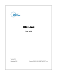
1
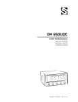
GUARANTEE
Y E A R S
OM 352
3 1/2 DIGIT PROGRAMMABLE
UNIVERSAL INSTRUMENT
AC/DC VOLTMETER/AMMETER
PROCESS MONITOR
OHMMETER
THERMOMETER FOR PT 100/500/1 000
THERMOMETER FOR NI 1 000
THERMOMETER FOR THERMOCOUPLES
DISPLAY INST. FOR LINEAR POTENTIOMETERS
SAFETY INSTRUCTIONS
Please, read the enclosed safety instructions carefully and observe them!
These instruments should be safeguarded by isolated or common fuses (breakers)!
For safety information the EN 61 010-1 + A2 standard must be observed.
This instrument is not explosion-safe!
TECHNICAL DATA
Measuring instruments of the OM 352 series conform to the European regulation 89/336/EWG
and the Ordinance 168/1997 Coll.
They are up to the following European and Czech standards:
CNS EN 55 022, class B
CNS EN 61000-4-2, -4, -5, -6, -8, -9, -10, -11
The instruments are applicable for unlimited use in agricultural and industrial areas.
CONNECTION
Supply of energy from the main line has to be isolated from the measuring leads.
ORBIT MERRET, spol. s r.o.
Vodňanská 675/30
198 00 Prague 9
Czech Republic
Tel: +420 - 281 040 200
Fax: +420 - 281 040 299
e-mail: [email protected]
www.orbit.merret.cz
2
|
INSTRUCTIONS FOR USE OM 352
CONTENS
1
1.
2.
3.
4.
Contens
..........................................................................................3
Instrument description. . . . . . . . . . . . . . . . . . . . . . . . . . . . . . . . . . . . . . . . . . . . . . . . . . . . . . . . . . . . . . . . . . . . . . . . . . . . . . . . . . . . 4
Instrument connection . . . . . . . . . . . . . . . . . . . . . . . . . . . . . . . . . . . . . . . . . . . . . . . . . . . . . . . . . . . . . . . . . . . . . . . . . . . . . . . . . . . . 6
Instrument setting . . . . . . . . . . . . . . . . . . . . . . . . . . . . . . . . . . . . . . . . . . . . . . . . . . . . . . . . . . . . . . . . . . . . . . . . . . . . . . . . . . . . . . . 8
Symbols used in the instructions . . . . . . . . . . . . . . . . . . . . . . . . . . . . . . . . . . . . . . . . . . . . . . . . . . . . . . . . . . . . . . . . . . . . . . . . . . . . . . . . . 10
Setting the DP and the (-) sing . . . . . . . . . . . . . . . . . . . . . . . . . . . . . . . . . . . . . . . . . . . . . . . . . . . . . . . . . . . . . . . . . . . . . . . . . . . . . . . . . . 10
Control keys functions
. . . . . . . . . . . . . . . . . . . . . . . . . . . . . . . . . . . . . . . . . . . . . . . . . . . . . . . . . . . . . . . . . . . . . . . . . . . . . . . . . . .11
Configuration of „User“ menu items . . . . . . . . . . . . . . . . . . . . . . . . . . . . . . . . . . . . . . . . . . . . . . . . . . . . . . . . . . . . . . . . . . . . . . . . . . . . . .11
5.
Setting “LIGHT” menu. . . . . . . . . . . . . . . . . . . . . . . . . . . . . . . . . . . . . . . . . . . . . . . . . . . . . . . . . . . . . . . . . . . . . . . . . . . . . . . . . . . 12
5.0 Description “LIGHT” menu . . . . . . . . . . . . . . . . . . . . . . . . . . . . . . . . . . . . . . . . . . . . . . . . . . . . . . . . . . . . . . . . . . . . . . . . . . . . . . . 12
Setting input type “DC” . . . . . . . . . . . . . . . . . . . . . . . . . . . . . . . . . . . . . . . . . . . . . . . . . . . . . . . . . . . . . . . . . . . . . . . . . . . . . . . . . .
Setting input type “AC” . . . . . . . . . . . . . . . . . . . . . . . . . . . . . . . . . . . . . . . . . . . . . . . . . . . . . . . . . . . . . . . . . . . . . . . . . . . . . . . . . .
Setting input type “PM” . . . . . . . . . . . . . . . . . . . . . . . . . . . . . . . . . . . . . . . . . . . . . . . . . . . . . . . . . . . . . . . . . . . . . . . . . . . . . . . . . .
Setting input type “OHM”. . . . . . . . . . . . . . . . . . . . . . . . . . . . . . . . . . . . . . . . . . . . . . . . . . . . . . . . . . . . . . . . . . . . . . . . . . . . . . . .
Setting input type “RTD-Pt” . . . . . . . . . . . . . . . . . . . . . . . . . . . . . . . . . . . . . . . . . . . . . . . . . . . . . . . . . . . . . . . . . . . . . . . . . . . . . . .
Setting input type “RTD-Cu” . . . . . . . . . . . . . . . . . . . . . . . . . . . . . . . . . . . . . . . . . . . . . . . . . . . . . . . . . . . . . . . . . . . . . . . . . . . . . .
Setting input type “RTD-Ni” . . . . . . . . . . . . . . . . . . . . . . . . . . . . . . . . . . . . . . . . . . . . . . . . . . . . . . . . . . . . . . . . . . . . . . . . . . . . . . .
Setting input type “T/C” . . . . . . . . . . . . . . . . . . . . . . . . . . . . . . . . . . . . . . . . . . . . . . . . . . . . . . . . . . . . . . . . . . . . . . . . . . . . . . . . .
Setting input type “DU” . . . . . . . . . . . . . . . . . . . . . . . . . . . . . . . . . . . . . . . . . . . . . . . . . . . . . . . . . . . . . . . . . . . . . . . . . . . . . . . . . .
Setting the limits
..................................................................................
Setting the analog output . . . . . . . . . . . . . . . . . . . . . . . . . . . . . . . . . . . . . . . . . . . . . . . . . . . . . . . . . . . . . . . . . . . . . . . . . . . . . . . .
Setting display color . . . . . . . . . . . . . . . . . . . . . . . . . . . . . . . . . . . . . . . . . . . . . . . . . . . . . . . . . . . . . . . . . . . . . . . . . . . . . . . . . .
Setting the menu type (LIGHT/PROFI) . . . . . . . . . . . . . . . . . . . . . . . . . . . . . . . . . . . . . . . . . . . . . . . . . . . . . . . . . . . . . . . . . . . . . .
Restoration of the manufacture setting . . . . . . . . . . . . . . . . . . . . . . . . . . . . . . . . . . . . . . . . . . . . . . . . . . . . . . . . . . . . . . . . . . . . . .
Calibration of the input range (DU) . . . . . . . . . . . . . . . . . . . . . . . . . . . . . . . . . . . . . . . . . . . . . . . . . . . . . . . . . . . . . . . . . . . . . . . .
Setting new access password . . . . . . . . . . . . . . . . . . . . . . . . . . . . . . . . . . . . . . . . . . . . . . . . . . . . . . . . . . . . . . . . . . . . . . . . . . . . .
Instrument identification . . . . . . . . . . . . . . . . . . . . . . . . . . . . . . . . . . . . . . . . . . . . . . . . . . . . . . . . . . . . . . . . . . . . . . . . . . . . . . . . . .
6.
16
18
20
22
24
26
28
30
32
34
35
36
38
38
39
40
40
Setting “PROFI” menu . . . . . . . . . . . . . . . . . . . . . . . . . . . . . . . . . . . . . . . . . . . . . . . . . . . . . . . . . . . . . . . . . . . . . . . . . . . . . . . . . . 44
6.0 Description “PROFI” menu . . . . . . . . . . . . . . . . . . . . . . . . . . . . . . . . . . . . . . . . . . . . . . . . . . . . . . . . . . . . . . . . . . . . . . . . . . . . . . . 44
6.1
“PROFI” menu - INPUT
6.1.1
Tare reseting . . . . . . . . . . . . . . . . . . . . . . . . . . . . . . . . . . . . . . . . . . . . . . . . . . . . . . . . . . . . . . . . . . . . . . . . . . . . . . . . . .
6.1.2
Setting the measuring range, displacement, compensation and measuring rate . . . . . . . . . . . . . . . . . . . . . . . . . . . . . .
6.1.3
Setting the external control input . . . . . . . . . . . . . . . . . . . . . . . . . . . . . . . . . . . . . . . . . . . . . . . . . . . . . . . . . . . . . . . . . . .
6.1.4
Setting function of the control key (ENTER) . . . . . . . . . . . . . . . . . . . . . . . . . . . . . . . . . . . . . . . . . . . . . . . . . . . . . . . . . . .
46
47
51
51
6.2
“PROFI” menu - CHANNELS
6.2.1
Projection on the display (MIN, MAX) . . . . . . . . . . . . . . . . . . . . . . . . . . . . . . . . . . . . . . . . . . . . . . . . . . . . . . . . . . . . . . 52
6.2.2 Setting the digital filter . . . . . . . . . . . . . . . . . . . . . . . . . . . . . . . . . . . . . . . . . . . . . . . . . . . . . . . . . . . . . . . . . . . . . . . . . . . 53
6.2.3 Setting the decimal point . . . . . . . . . . . . . . . . . . . . . . . . . . . . . . . . . . . . . . . . . . . . . . . . . . . . . . . . . . . . . . . . . . . . . . . . . 53
6.3
“PROFI” menu - INPUTS
6.3.1
Configuration and setting the limits . . . . . . . . . . . . . . . . . . . . . . . . . . . . . . . . . . . . . . . . . . . . . . . . . . . . . . . . . . . . . . . . .
6.3.2 Setting the data output . . . . . . . . . . . . . . . . . . . . . . . . . . . . . . . . . . . . . . . . . . . . . . . . . . . . . . . . . . . . . . . . . . . . . . . . . . .
6.3.3 Setting the analog output . . . . . . . . . . . . . . . . . . . . . . . . . . . . . . . . . . . . . . . . . . . . . . . . . . . . . . . . . . . . . . . . . . . . . . . . .
6.3.4 Setting the display brightness . . . . . . . . . . . . . . . . . . . . . . . . . . . . . . . . . . . . . . . . . . . . . . . . . . . . . . . . . . . . . . . . . . . . . .
54
55
56
57
“PROFI” menu - SERVICE
6.4.1
Selection of the type of programming menu . . . . . . . . . . . . . . . . . . . . . . . . . . . . . . . . . . . . . . . . . . . . . . . . . . . . . . . . . .
6.4.2 Restiration of the manufacture setting. . . . . . . . . . . . . . . . . . . . . . . . . . . . . . . . . . . . . . . . . . . . . . . . . . . . . . . . . . . . . . . .
6.4.3 Calibration of the input range (DU) . . . . . . . . . . . . . . . . . . . . . . . . . . . . . . . . . . . . . . . . . . . . . . . . . . . . . . . . . . . . . . . . .
6.4.4 Setting new access password . . . . . . . . . . . . . . . . . . . . . . . . . . . . . . . . . . . . . . . . . . . . . . . . . . . . . . . . . . . . . . . . . . . . .
6.4.5 Instrument identification . . . . . . . . . . . . . . . . . . . . . . . . . . . . . . . . . . . . . . . . . . . . . . . . . . . . . . . . . . . . . . . . . . . . . . . . . .
60
61
61
61
62
6.4
7.
Setting “USER” menu . . . . . . . . . . . . . . . . . . . . . . . . . . . . . . . . . . . . . . . . . . . . . . . . . . . . . . . . . . . . . . . . . . . . . . . . . . . . . . . . . . . 64
7.0 Configuration “USER” menu . . . . . . . . . . . . . . . . . . . . . . . . . . . . . . . . . . . . . . . . . . . . . . . . . . . . . . . . . . . . . . . . . . . . . . . . . . . . . . 64
8.
9.
10.
11.
12.
13.
Method of measuring of the cold junction . . . . . . . . . . . . . . . . . . . . . . . . . . . . . . . . . . . . . . . . . . . . . . . . . . . . . . . . . . . . . . . . . . 66
Data protocol . . . . . . . . . . . . . . . . . . . . . . . . . . . . . . . . . . . . . . . . . . . . . . . . . . . . . . . . . . . . . . . . . . . . . . . . . . . . . . . . . . . . . . . . . 67
Error statements . . . . . . . . . . . . . . . . . . . . . . . . . . . . . . . . . . . . . . . . . . . . . . . . . . . . . . . . . . . . . . . . . . . . . . . . . . . . . . . . . . . . . . . 68
Technical data . . . . . . . . . . . . . . . . . . . . . . . . . . . . . . . . . . . . . . . . . . . . . . . . . . . . . . . . . . . . . . . . . . . . . . . . . . . . . . . . . . . . . . . . . 70
Instrument dimension and installation . . . . . . . . . . . . . . . . . . . . . . . . . . . . . . . . . . . . . . . . . . . . . . . . . . . . . . . . . . . . . . . . . . . . . 72
Certificate of guarantee . . . . . . . . . . . . . . . . . . . . . . . . . . . . . . . . . . . . . . . . . . . . . . . . . . . . . . . . . . . . . . . . . . . . . . . . . . . . . . . . . 73
INSTRUCTIONS FOR USE OM 352
|
3
2
INSTRUMENT DESCRIPTION
2.1
Description
The OM 352 model series are 3 1/2 digit lowcost panel programmable instruments designed for maximum efficiency and
user comfort while maintaining their favourable price. Three models are available: UNI, DC and PWR.
Type OM 352UNI is a multifunction instrument with the option of configuration for 7 various input options, easily configurable
in the instrument menu.
The instrument is based on an 8-bit microcontroller with a multichannel 10-bit sigma-delta converter, which secures good
accuracy, stability and easy operation of the instrument.
The OM 352 is a multifunction instrument available in following types and ranges
type UNI
DC:
0…20/60/1000 mV
PM:
0…20 mA/4…20 mA/0…2 V/0…5 V/0…10 V
OHM:
0…300 Ϊ; 0…1500 Ϊ; 0…3 kΪ; 0…30 kΪ
RTD-Pt:
Pt 50; Pt 100; Pt 500; Pt 1000
RTD-Cu:
Cu 50; Cu 100
RTD-Ni:
Ni 1 000; Ni 10 000
T/C:
J/K/T/E/B/S/R/N/L
DU:
Linear potentiometer (min. 500 Ϊ)
type DC
DC:
0…500 mA/0…1 A/0…5 A/ 0…20 V/0…40 V/0…200 V
type AC
AC:
0…1 A/0…5 A/0…60 mV/0…300 mV/0…24 V/0…50 V/0…90 V/0…120 V/0…250 V/0…450 V
PROGRAMMABLE PROJECTION
Selection:
Measuring range:
Setting:
Projection:
of type of input and measuring range
adjustable or fixed
manual, optional projection on the display may be set in the menu for both limit values of the input
signal , e.g. input 0…20 mA > 0…150,0
±1999, (for 20 mm display -999…9999)
LINEARIZATION
Linearization:*
by linear interpolation in 25 points (solely via OM Link)
COMPENSATION
of conduct:
of conduct in probe:
of CJC (T/C):
in the menu it is possible to perform compensation for 2-wire connection
internal connection (conduct resistance in measuring head)
manual or automatic, in the menu it is possible to perform selection of the type of thermocouple
and compensation of cold junctions, which is adjustable or automatic (temperature at the brackets)
DIGITAL FILTERS
Exponen.average:
Rounding:
from 2…100 measurements
setting the projection step for display
MATHEMATIC FUCTIONS
Tare*:
designed to reset display upon non-zero input signal
EXTERNAL CONTROL
Hold
Lock
Tára*
4
|
display/instrument blocking
locking the control keys for access into Configuration menu
tare activation
INSTRUCTIONS FOR USE OM 352
* Does not apply for version RTD, T/C
INSTRUMENT DESCRIPTION
2.2
2
Operationn
The instrument is set and controlled by five control keys located on the front panel. All programmable settings of the instrument are realized in two adjusting modes:
LIGHT
Simple programming menu
- contains only items necessary for instrument setting and is protected by an optional numeral code
PROFI
Complete programming menu
- contains complete instrument menu and is protected by an optional numeral code
USER
User programmable menu
- may contain arbitrary items selected from programmable menu (LIGHT/PROFI), which determines
the authorization (see or change)
- access is without password
All programmable parameters are stored in the EEPROM memory
(they hold even after the instrument is switched off).
Complete operation and setting of the instrument may be performed via communication interface
OM Link, which is a standard equipment of every instrument.
The operation program is freely available (www.orbit.merret.cz) and the only requirement is the
purchase of OML cable for connecting the instrument to PC. It is manufactured in version RS 232 and USB and is compatible
with all ORBIT MERRET instruments.
Another option for connection is with the aid of data output RS 232 or RS 485 (without the need for OML cable).
The OM LINK program version „Standard“ allows you to connect an unlimited number of instruments with the option of
visualizatiion and storage in PC.
2.3
Extension
Excitation is suitable for feeding sensors and converters. It has a galvanic isolation.
Comparators are assigned to control two limit values with relay output. The limits have adjustable hysteresis as well as
selectable delay of the switch-on. Reaching the preset limits is signalled by LED and simultaneously by the switch-on of the
relevant relay.
Data outputs are for their rate and accuracy suitable for transmission of measured data for further projection or directly
into the control systems. We offer an isolated RS232 and RS485 with the ASCII protocol.
Analog outputs will find their place in applications where further evaluating or processing of measured data in external
devices is required. We offer a universal analog output with the option of selection of output type - voltage/current. The value
of analog output corresponds with the displayed data and its type and range are selectable in the programming mode.
INSTRUCTIONS FOR USE OM 352
|
5
3
INSTRUMENT CONNECTION
The instrument supply leads should not be in proximity of the incoming low-potential signals.
Contactors, motors with larger input power should not be in proximity of the instrument.
The leads into the instrument input (measured quantity) should be in sufficient distance from all power leads and appliances.
Provided this cannot be secured it is necessary to use shielded leads with connection to ground (bracket E).
The instruments are tested in compliance with standards for use in industrial area, yet we recommend to abide by the above
mentioned principles.
Measuring ranges
OM 352UNI
Type
Input 1
DC
0…1 000 mV
PM
0…5/10 V
Input 2
Input 3
Input 4
0…60 mV
0…20 mV
0…2 V
OHM
0…300 Ϊ • 0…1,5 kΪ • 0…3 kΪ • 0…30 kΪ
RTD-Pt
Pt 100 • Pt 500 • Pt 1 000
RTD-Cu
Cu 50 •Cu 100
RTD-Ni
Ni 1 000 •Ni 10 000
T/C
B/R/S/ T
DU
Linear potentiometer (min. 500 Ϊ)
Input 5
0/4…20 mA
E/J/K/N/L
OM 352DC
Type
Input 1
Input 2
Input 3
Input 4
0…20/40/200 V
DC
Input 5
0…0,5/1/5 A
OM 352AC
Type
Input 1
Input 2
Input 3
Input 4
Input 5
DC
0…90/450 V
0…50/250 V
0…24/120 V
0…60/300 mV
0…1/5 A
6
|
INSTRUCTIONS FOR USE OM 352
INSTRUMENT CONNECTION
1
2
3
4
5
5
6
7
8
9 10
3
11 12 13 14 15 16 17 18
+
CJC
-
+ - + + + +
1
2
3
4
5
Rx/Tx+
Rx/TxGND
L2
L1
RTD, OHM, Ni
485
E-- SE-- SES-
- + +
AO - U
AO - I
GND
POWER SUPPLY
Hold/Lock
INPUT
INPUT
INPUT
INPUT
GND
INPUT
RxD
TxD
GND
N
E
L
232
DC, PM
S+ E+
ES+
ES+
- + +
T/C
INPUT 3
INPUT 4
GND
+ Excitation
+
-
DU
!
!
Grounding on terminal „E“ has to be connected at all times.
In case of RTD and OHM inputs with 2- or 3- wire connection
it is necessary to link the unconnected inputs on the terminal
board (14+15/16+17 or 16+17).
The OM Link connector has galvanic interconnection
with bracket 14.
INSTRUCTIONS FOR USE OM 352
|
7
4
INSTRUMENT SETTING
• For expert users
• Complete instrument menu
PROFI
• Access is password protected
Setting
• Possibility to arrange items of the
„User“ menu
• Tree menu structure
• For trained users
LIGHT
• Only items necessary for instrument
setting
• Access is password protected
Setting
• Possibility to arrange items of the
„User“ menu
• Linear menu structure
USER
• For user operation
• Menu items are set by the user
(Profi/Light) as per request
Setting
• Access is not password protected
• Optional menu structure either tree
(PROFI) or linear (LIGHT)
8
|
INSTRUCTIONS FOR USE OM 352
INSTRUMENT SETTING
4.1
4
Setting
The instrument is set and controlled by five control keys located on the front panel. All programmable settings of the instrument
are performed in three adjusting modes:
LIGHT
Simple programming menu
- contains solely items necessary for instrument setting and is protected by optional number code
PROFI
Complete programming menu
- contains complete instrument menu and is protected by optional number code
USER
User programming menu
- may contain arbitrary items selected from the programming menu (LIGHT/PROFI), which determine
the right (see or change)
- acces without password
All programmable parameters are stored in the EEPROM memory (they hold even after the instrument is switched off).
Complete instrument operation and setting may be performed via OM Link communication interface, which is a standard
equipment of all instruments.
The operation program is freely accessible (www.orbit.merret.cz) and the only requirement is the purchase of OML cable
to connect the instrument to PC. It is manufactured in version RS 232 and USB and is compatible with all ORBIT MERRET
instruments.
Another option for connection is with the aid of data output RS 232 or RS 485 (without the need of the OML cable).
INSTRUCTIONS FOR USE OM 352
|
9
4
INSTRUMENT SETTING
Setting and controlling the instrument is performed by means of 5 control keys located on the front panel. With the aid of
these keys it is possble to browse through the operation menu and to select and set required values.
Measured value
Relay status
ON the digit is lit
OFF the digit is not lit
OFF the digit is flashing
limits with restriction
(delay)
143.7
1
2
Function
T
M
Tare
T
Symbols used in the instructions
AC
DC
DU
PM
OHM RTD
T/C
Indicates the setting for given type of instrument
values preset from manufacture
DEF
42
MIN
CONECT.
30
symbol indicates a flashing light (symbol)
inverted triangle indicates the item that can be placed in USER menu
broken line indicates a dynamic item, i.e. it is displayed only in particular selection/version
after pressing the key the set value will not be stored
after pressing the key the set value will be stored
continues on page 30
Setting the decimal point and the minus sign
DECIMAL POINT
Its selection in the menu, upon modification of the number to be adjusted it is performed by the control key
beyond the highest decade, when the decimal point starts flashing . Positioning is performed by / .
with transition
THE MINUS SIGN
Setting the minus sign is performed by the key on higher decade. When editing the item substraction must be made from
the current number (e.g..: 013 > , on class 100 > -87)
10
|
INSTRUCTIONS FOR USE OM 352
INSTRUMENT SETTING
4
Controntrol keys functions
Key
Measurement
Menu
Setting numbers/Selection
access into USER menu
exit menu w/o saving
transition to next item w/o
saving
tare value (DC, PM)
resistance measured (RTD)
back to previous level
cold junctions temperature (T/C)
move to higher decade
cancel Tare
move to previous item
move down
cancel Tare
move to next item
move up
Tare
confirm selection
setting/selection confirmation
+
access into LIGHT/PROFI menu
+
direct access into PROFI menu
- temporary (remains LIGHT)
configuration of an item for
USER menu
+
Setting items into „USER“ menu
• in LIGHT or PROFI menu
• no items permitted in USER menu from manufacture
• on items marked by inverted triangle
legend is flashing - current setting is displayed
--NO
+
NO
YES
SHO
return to item
---
item will not be displayed in USER menu
YES
item will be displayed in USER menu with the option of setting
SHO
item will be solely displayed in USER menu
INSTRUCTIONS FOR USE OM 352
|
11
5
SETTING
5.0
light
Setting “Light”
LIGHT
Simple programming menu
- contains only items necessary for instrument setting and is protected by optional numeral code
• For capable users
LIGHT
• Only items necessary for instrument
setting
• Password protected access
SETTING
• Possibility to arrange items of the
„User“ menu
• Linear menu structure
Preset from manufacture
Password
Menu
USR menu
Setting the items
12
|
INSTRUCTIONS FOR USE OM 352
“0”
LIGHT
off
DEF
light
SETTING
5
142. 8
!
+
Upon delay exceeding 60 s the programming mode
is automatically discontinued and the instrument
itself restores the measuring mode
Access code
PAS
0
TYP.
DC
MOD.
60m
CON
4-u
FOR.
00. o
CON
EX.1
T. C. J
0
FOR.
000
MIN.
0
MAX.
100
FOR.
00. o
L.1
25
L. 2
75
Selecting input, range
RTD OHM
Selecting projection, connection
T/C
DC
PM OHM DU
Option - Comparator
Option - Analog output
A. T.
I 20
GRE.
Second color’s limit
d . L1. .
0
First color’s limit
Basic color
Co . 0 .
A. Lo
d . L1. .
A. Hi
Color after the first limit
9999
Co . 2.
Color after the second limit
9999
Menu type
Co . 2.
100
RED
Options - Color display
ORA.
Return to manufacture setting
MNU
LIG.
RES.
YES
C. Lo
YES
C. Hi
YES
DU
Calibration - only for “DU”
New password
N. PA.
Return to previous measuring mode
Identification
0
ID.
YES
OM 352. . . .
142. 8
INSTRUCTIONS FOR USE OM 352
|
13
5
SETTING
light
142. 8
PAS.
0
PAS.
Entering access password
for access into the menu
Access into instrument
menu
DC
PAS = 0
- access into menu is unrestricted, after
releasing keys you automaticaly move to first
item of the menu
PM
DU OHM RTD T/C
PAS > 0
- access into menu is protected ny number
code
Example
Set “Password” = 42
0
1
2
32
42
MOD.
TYP.
DC
PM
OHM
Ni
TC
DU
TYP.
02
12
Pt
Cu
14
|
16
18
20
22
24
26
28
30
32
Selection of the type of
instrument
Menu
Type „DC“
Type “352AC“
Type “PM”
Type “OHM“
Type “Pt“
Type “Cu”
Type “Ni”
Type “T/C“
Type “DU”
22
Type of instrument
DC
DC voltmeter
- performs default setting DEF of values
from manufacture, incl. calibration
PM
Process monitor
INSTRUCTIONS FOR USE OM 352
OHM
Ohmmeter
RTD
Thermometer for sensors Pt
Cu
Thermometer for sensors Cu
Ni
Thermometer for sensors Ni
TC
Thermometer for thermocouples
DU
Display for lin. potentiometer
Example
Type “PM”
DC
TYP.
- primary selection of the type of instrument
PM
MOD.
light
SETTING
INSTRUCTIONS FOR USE OM 352
|
5
15
5
SETTING
light
Type “DC”
DC
OM 352UNI
MOD.
20m
60m
U 1.
DC
OM 352DC
DC
i0.5
i1. 0
i5. 0
u20
u40
200
DC
DC
MOD.
Selection of the instrument
measuring range
Menu
MOD.
DC
DEF = 60 mV (OM 352UNI)
DEF = 200 V (OM 352DC)
0…20 mV
60m
0…60 mV
U 1.
0…1 000 mV
i0.5
0…500 mA
i1.0
0…1 A
i5.0
DC
DC
0…20 V
u40
0…40 V
200
0…200 V
Example
20m
MIN
DC
DC
MIN
0
DC
MIN
0…5 A
u20
Range 0…20 mV
60m
Measuring ranges
20m
Setting for minimum
input signal
Setting display projection
for minimum value of
input signal
DC
- range of the setting is ±1999
- position of the DP does not affect display
projection
- the DP is automatically shifted after the
value is confirmed
DEF = 0
Projection for 0 mV > MIN = 0
DC
0
16
|
INSTRUCTIONS FOR USE OM 352
MAX
Example
light
100
Setting for maximum
input signal
Setting display projection
for maximum value of
- range of the setting is
±1999
- position of the DP does not affect display
projection
- the DP is automatically shifted after the
value is confirmed
DC
input signal
DC
MAX
5
DC
MAX
SETTING
DC
DEF = 100
Example
Projection for 20 mV > MAX = 1500
100
100
200
500
0500
1500
FOR.
300
400
DC
100
DC
0. o o
Setting projection of the
decimal point
. ooo
FL. P.
DC
FOR.
00. o
DC
000
DC
FOR.
DEF = 00.o
DC
- positioning of the DP is set here in the
measuring mode
Example
Projection of DP on display > 000
000
MNU
DC
00. o
*subsequent item on the menu depends on instrument equipment
DC
DC
34
INSTRUCTIONS FOR USE OM 352
|
17
5
SETTING
light
AC
OM 352AC
AC
MOD.
i 1.
i 5.
60m
u0.3
u90
120
250
450
u24
u50
AC
AC
MOD.
Selection of the instrument
measuring range
AC
AC
MOD ./ OM 352AC
DEF = 250 V
Menu
Measuring ranges
i 1.
0…1 A
AC
i 5.
0…5 A
60m
0…60 mV
u0.3
0…300 mV
u24
0…24 V
u50
0…50 V
u90
0…90 V
120
0…120 V
250
0…250 V
450
0…450 V
AC
Example
Range 0…50 V
250
120
u90
AC
AC
MIN
0
AC
MIN
Setting for minimum
input signal
Setting display projection
for minimum value of
input signal
AC
- range of the setting is ±1999
u50
MIN
- position of the DP does not affect display
projection
- the DP is automatically shifted after the
value is confirmed
DEF = 0
Example
AC
Projection for 0 A > MIN = 0
0
AC
18
|
INSTRUCTIONS FOR USE OM 352
MAX
light
100
Setting for maximum
input signal
input signal
±1999
AC
- range of the setting is
- position of the DP does not affect display
projection
- the DP is automatically shifted after the
value is confirmed
AC
Setting display projection
for maximum value of
AC
MAX
5
AC
MAX
SETTING
DEF = 100
Example
Projection for 5 A > Max = 350
100
110
120
130
150
150
250
350
FOR
140
AC
100
AC
AC
000
00. o
0. o o
. ooo
FL. P.
AC
FOR
AC
FOR
DEF = 00.o
AC
Setting projection of the
decimal point
- positioning of the DP is set here in the
measuring mode
00. o
MnU
AC
Example
Projection of DP on display > 00.o
*subsequent item on the menu depends on instrument equipment
AC
AC
AC
34
INSTRUCTIONS FOR USE OM 352
|
19
5
SETTING
light
Type “PM”
u 2.
PM
MOD.
u 5.
u 10.
i 0.
i 4.
Selection of the instrument
measuring range
PM
MOD.
PM
MOD.
DEF = I 4
Menu
Measuring ranges
U 2.
0…2 V
PM
U 5.
0…5 V
U 10.
0…10 V
I 0.
0…20 mA
I 4.
4…20 mA
Example
Range 4…20 mA
PM
i 4.
MIN
PM
PM
MIN
0
PM
MIN
Setting for minimum
input signal
Setting display projection
for minimum value of
input signal
PM
- range of the setting is ±1999
- position of the DP does not affect display
projection
- the DP is automatically shifted after the
value is confirmed
DEF = 0
Example
PM
Projection for 4 mA > Min = -25
0
1
2
3
05
15
25
MAX
PM
PM
20
|
INSTRUCTIONS FOR USE OM 352
4
5
light
100
Setting for maximum
input signal
Setting display projection
for maximum value of
input signal
±1999
- position of the DP does not affect display
projection
- the DP is automatically shifted after the
value is confirmed
PM
- range of the setting is
PM
MAX
5
PM
MAX
SETTING
DEF = 100
100
100
110
120
150
150
250
FOR
130
PM
Example
Projection for 20 mA > Max = 250
140
PM
PM
000
0. o o
Setting projection of the
decimal point
. ooo
FL. P.
PM
FOR
00. o
PM
FOR
DEF = 00.o
PM
- positioning of the DP is set here in the
measuring mode
Example
Projection of DP on display > 000
000
MNU
PM
00. o
*subsequent item on the menu depends on instrument equipment
PM
PM
34
INSTRUCTIONS FOR USE OM 352
|
21
5
SETTING
light
Type “OHM”
2-u
OHM
CON
3-u
4-u
Selection of the type of
sensor connection
OHM
- in 2- or 3- wire connection it is necessary
to link the unconnected inputs (see Chapter
Connection)
CON.
OHM
CON
Menu
Connection
2-u
2-wire
3-u
3-wire
4-u
4-wire
DEF = 2-wire
Example
Type of connection - 3 wire > COn = 3-u
2-u
3-u
MIN
OHM
OHM
MIN
0
OHM
MIN
Setting for minimum
input signal
Setting display projection
for minimum value of
OHM
input signal
- range of the setting is ±1999
- position of the DP does not affect display
projection
- the DP is automatically shifted after the
value is confirmed
DEF = 0
Projection for 0 Ohm > MIN = 0
OHM
0
OHM
22
|
INSTRUCTIONS FOR USE OM 352
MAX
Example
light
100
Setting for maximum
input signal
Setting display projection
for maximum value of
input signal
- range of the setting is ±1999
OHM
MAX
5
OHM
MAX
SETTING
- position of the DP does not affect display
projection
- the DP is automatically shifted after the
value is confirmed
OHM
DEF = 100
Example
Projection for 300 Ohm > MAX = 350
100
100
110
120
130
150
150
250
350
FOR
140
OHM
000
0. o o
Setting projection of the
decimal point
. ooo
FL. P.
OHM
FOR
00. o
OHM
FOR
DEF = 00.0
OHM
- positioning of the DP is set here in the
measuring mode
Example
Projection of DP on display > 000
00. o
000
MNU
*subsequent item on the menu depends on instrument equipment
OHM
OHM
34
INSTRUCTIONS FOR USE OM 352
|
23
5
SETTING
light
Type “Pt”
Pt
MOD.
E. 1
U. 1
r. 0 .5
r. 1
Pt
Selection of instrument
measuring range
Pt
- setting the input range depends on ordered
measuring range
Pt
C B
DEF = E. 1
A
Pt
MOD.
Menu
Measuring range
E. 1
Pt 100 (3 850 ppm/°C)
U. 1
Pt 100 (3 920 ppm/°C)
R.0.5
Pt 50 (3 910 ppm/°C)
R. 1
Pt 100 (3 910 ppm/°C)
E. 5
Pt 500 (3 850 ppm/°C)
E.10
Pt 1000 (3 850 ppm/°C)
Pt
* letter in the first column marks the measuring range as
per the order
Pt
Example
Type of sensor Pt 100 > E. 1
Pt
E. 1
CON
Pt
Pt
2-u
Pt
CON
3-u
4-u
Selection of the type of
sensor connection
Pt
- in 2- or 3- wire connection it is necessary
to link the unconnected inputs (see Chapter
Connection)
CON.
Pt
CON
Menu
Connection
2-u
2-wire
3-u
3-wire
4-u
4-wire
Pt
DEF = 4-wire
Example
Type of connection - 3 wire > COn = 3-u
Pt
4-u
Pt
24
|
INSTRUCTIONS FOR USE OM 352
3-u
FOR
light
000
00. o
0. o o
. ooo
FL. P.
5
Pt
FOR
SETTING
Pt
Setting projection of the
decimal point
DEF = 00.0
Example
Projection of DP on display > 000
00. o
000
Pt
- positioning of the DP is set here in the
measuring mode
000. > for range -50°…400°C
00.0 > for range -50,0°…199,9°C
Pt
FOR
MNU
*subsequent item on the menu depends on instrument equipment
Pt
Pt
Pt
Pt
Pt
34
Pt
Pt
Pt
Pt
Pt
Pt
INSTRUCTIONS FOR USE OM 352
|
25
5
SETTING
light
Type “Cu”
Cu
MOD.
Cu 1.
Cu . 2
Cu .3
Cu 4.
Cu
Selection of instrument
measuring range
- setting the input range depends on ordered
measuring range
Cu
DEF = Cu.2
Cu
Type of sensor Cu 100/4 280 ppm > Cu.2
Cu
Cu . 2
MOD.
Cu
MOD.
Menu
Measuring range
Cu.1
Cu.2
Cu.3
Cu.4
Cu 50 (4 280 ppm/°C)
Cu 100 (4 280 ppm/°C)
Cu 50 (4 260 ppm/°C)
Cu 100 (4 260 ppm/°C)
Cu
Example
CON
Cu
Cu
2-u
Cu
CON
3-u
4-u
Selection of the type of
sensor connection
Cu
- in 2- or 3- wire connection it is necessary
to link the unconnected inputs (see Chapter
Connection)
CON.
Cu
CON
Menu
Connection
2-u
2-wire
3-u
3-wire
4-u
4-wire
DEF = 4-wire
Cu
Example
Type of connection - 3 wire > COn = 3-u
4-u
Cu
Cu
26
|
INSTRUCTIONS FOR USE OM 352
3-u
FOR
light
000
00. o
0. o o
. ooo
FL. P.
5
Cu
FOR
SETTING
Cu
Setting projection of the
decimal point
- positioning of the DP is set here in the
measuring mode
DEF = 00.0
000
Cu
Example
Projection of DP on display > 000
00. o
Cu
FOR
MNU
*subsequent item on the menu depends on instrument equipment
Cu
Cu
Cu
Cu
34
Cu
Cu
Cu
Cu
Cu
Cu
INSTRUCTIONS FOR USE OM 352
|
27
5
SETTING
light
Ni
MOD.
NI.5
Ni
MOD.
NI. 6
Ni
Selection of instrument
measuring range
Ni
D
- setting the input range depends on ordered
measuring range
C
Ni
Type “Ni”
DEF = Ni.5
Menu
Measuring range
Ni.5
Ni.6
Ni.5
Ni.6
Ni 1 000 (5 000 ppm/°C)
Ni 1 000 (6 180 ppm/°C)
Ni 10 000 (5 000 ppm/°C)
Ni 10 000 (6 180 ppm/°C)
Ni
* letter in the first column marks the measuring range as
per the order
Ni
Ni
Example
Type of sensor Ni 1 000/5 000 ppm > NI.5
NI.5
CON
Ni
Ni
Ni
2-u
Ni
CON
3-u
4-u
Selection of the type of
sensor connection
Ni
- in 2- or 3- wire connection it is necessary
to link the unconnected inputs (see Chapter
Connection)
CON.
Ni
CON
Menu
Connection
2-u
2-wire
3-u
3-wire
4-u
4-wire
Ni
DEF = 4-wire
Example
Ni
Type of connection - 3 wire > COn = 3-u
4-u
Ni
Ni
28
|
INSTRUCTIONS FOR USE OM 352
3-u
FOR
light
000
0. o o
. ooo
FL. P.
Ni
Setting projection of the
decimal point
DEF = 00.0
Ni
Example
Projection of DP on display > 000
000
Ni
- positioning of the DP is set here in the
measuring mode
00. o
Ni
FOR
00. o
5
Ni
FOR
SETTING
MNU
*subsequent item on the menu depends on instrument equipment
Ni
Ni
Ni
Ni
Ni
34
Ni
Ni
Ni
Ni
Ni
Ni
Ni
INSTRUCTIONS FOR USE OM 352
|
29
5
light
SETTING
Type “T/C”
T/C
B
E
J
K
R
S
T
L
N >
MOD.
>
T/C
T/C
MOD.
Selection of the type of
thermocouple
T/C
MOD.
DEF = Type “J”
Menu
Type of thermocouple
B
T/C B
E
T/C E
J
T/C J
T/C
K
T/C K
N
T/C N
R
T/C R
S
T/C S
T
T/C T
L
T/C L
Example
Type of thermocouple “K”
J
K
CON.
T/C
CON.
T/C
IN.1
T/C
CON.
IN. 2
EX.1
CON.
T/C
T/C
EX. 2
T/C
!
For thermocoule type “B” the items CON.
and C.J. T. are not available
|
INSTRUCTIONS FOR USE OM 352
Menu Connection
Ref. T/C
IN.1
measuring C.J. at instrument
brackets
IN.2
measuring C. J. at
instrument brackets with
anti-series connected ref. TC
EX.1
the entire measuring set is
working under invaried and
constant temperature
EX.2
when using compensation
box
Example
Sensor connection > CON = EX. 2
30
EX. 2
Selection of the type of
sensor connection
DEF = EX. 1
EX.1
T. C. J .
light
0
Setting temperature of
cold junction
Setting temperature of cold
junction
T/C
T. C. J .
5
T/C
T. C. J .
SETTING
DEF = 0
Example
Setting temperature of cold junction > T.C.J. = 35
23
T/C
- range -20…99°C with compensation box
24
25
25
35
FOR.
T/C
T/C
0. o o
. ooo
FL. P.
DEF = 000
T/C
Example
Projection of DP on display > 00.o
00. o
T/C
Setting projection of the
decimal point
- positioning of the DP is set here in the
measuring mode
000
T/C
FOR
00. o
T/C
000
FOR
MNU
*subsequent item on the menu depends on instrument equipment
T/C
!
Method and procedure of setting the cold junctions is
described in separate chapter on page 66
T/C
34
INSTRUCTIONS FOR USE OM 352
|
31
5
SETTING
light
Type “DU”
DU
MIN
0
DU
DU
MIN
Setting for minimum
input signal
Setting display projection
for minimum value of
input signal
DU
- range of the setting is ±1999
- position of the DP does not affect display
projection
- the DP is automatically shifted after the
value is confirmed
DEF = 0
Example
Projection for begin > MIN = 0
DU
0
MAX
DU
DU
MAX
100
Setting for maximum
input signal
DU
DU
MAX
Setting display projection
for maximum value of
input signal
- range of the setting is ±1999
- position of the DP does not affect display
projection
- the DP is automatically shifted after the
value is confirmed
DU
DEF = 100
Example
Projection for end > MAX = 50
DU
100
100
110
120
150
150
050
FOR
DU
DU
32
|
INSTRUCTIONS FOR USE OM 352
130
140
light
000
0. o o
FL. P.
DEF = 00.0
DU
Setting projection of the
decimal point
. ooo
DU
FOR
00. o
5
DU
FOR
SETTING
- positioning of the DP is set here in the
measuring mode
00. o
000
MNU
DU
Example
Projection of DP on display > 000
*subsequent item on the menu depends on instrument equipment
DU
DU
DU
34
Calibration of the beginning and the end of
range of linear potentiometer is on page 41
DU
DU
DU
DU
DU
DU
INSTRUCTIONS FOR USE OM 352
|
33
5
SETTING
L1
light
25
L1
Setting the boundary
for limit 1
Setting the boundary for
limit 1
- range of the setting is ±1999
- presetting “Hysteresis”=0 “Delay”=0
- contingent change of hysteresis or offset
of the switch-on may be performed in the
PROFI menu
DEF = 25
Only with option > Dual Comparator
Example
Setting limit 1 > L 1 = 30
L2
25
26
27
20
30
L2
75
L2
28
29
20
Setting the boundary
for limit 2
Setting the boundary for
limit 2
- range of the setting is ±1999
- presetting “Hysteresis”=0 “Delay”=0
- contingent change of hysteresis or offset
of the switch-on may be performed in the
PROFI menu
DEF = 75
Example
Setting limit 2 > L 2 = 230
100
100
230
MNU
110
120
130
130
* following item of the menu depends on instrument equipment, provided it has an analog
output the following item is „Type“
!
Items for “Limits” and “Analog output” are accessible only if the instrument contains them.
34
|
INSTRUCTIONS FOR USE OM 352
light
A. T.
I 20
E4
I 4
I 5
U2
Setting the type of analog
output
Menu
Range
i20
0…20 mA
U5
U 10
DEF = E 4
Description
4…20 mA
i4
4…20 mA
i5
0…5 mA
U2
0…2 V
U5
0…5 V
U10
0…10 V
with indication of error statement (<3,6 mA)
Example
Type of analog output - 0...10 V > A. t. = U 10
i5
0
A. Lo
A. Lo
Only with option > Analog output
E4
i4
5
A. T.
SETTING
U2
U5
A. Lo
Assigning the display
value to the beginning of
the AO range
Assigning the display
value to the beginning of
U 10
DEF = 0; (40 > RTD, T/C)
the AO range
- range of the setting is ±1999
Example
Display value for the beginning of the AO range > A.Lo = 0
0
A. Hi
100
A. Hi
A. Lo
Assigning the display
value to the end of the
AO range
Assigning the display
value to the end of the
DEF = 100; (199.9 > RTD, T/C)
AO range
- range of the setting is ±1999
Example
Display value for the end of the AO range > A.Hi = 120
100
100
110
120
MNU
INSTRUCTIONS FOR USE OM 352
|
35
5
SETTING
Co . 0 .
light
RED.
GRE. .
ORA. .
Selection of display color
> basic setting
Co . 0 .
Only with option > 3-color 20 mm display
DEF = green
Example
Selection of display color - basic > red
GRE.
d . L1. .
RED.
Setting limit for the
change of display color
9999
d . L1. .
d . L1. .
Setting first value for the
change of display color
DEF = 9999
- range of the setting -999…9999
Example
Display value for 1st color change > 100
9999
Co 1. .
RED.
Co 1. .
+
0
GRE.
00
ORA.
Selection of display color
> after exceeding d.L. 1.
000
100
Co 1. .
DEF = orange
- selection of display color is governed by the
setting under step d.L.1.
- display color changes when the value on
the display exceeds the color set in d.L.1.
Selection of display color if the value is > d.L.1 > green
ORA.
36
|
INSTRUCTIONS FOR USE OM 352
GRE.
d . L. 2 .
Example
light
d . L. 2 .
d . L. 2 .
5
Setting limit for the
change of display color
9999
SETTING
Setting second value for the
change of display color
DEF = 9999
Example
Display value for 2nd color change > 400
9999
200
Co . 2.
RED.
Co . 2.
+
0
300
GRE.
Only with option > 3-color 20 mm display
- range of the setting -999…9999
00
400
ORA.
Selection of display color
> after exceeding d.L. 2.
000
100
Co . 2.
DEF = red
- selection of display color is governed by the
setting under step d.L.2.
- display color changes when the value on
the display exceeds the color set in d.L.2.
Selection of display color if the value is > d.L.2 > orange
RED.
ORA.
Example
MNU.
40
INSTRUCTIONS FOR USE OM 352
|
37
profi
SETTING
142. 8
+
PAS.
0
INP.
CHA.
CLR.
C.tA.
SET.
CFG.
M. P. S .
0.5 1.2 2.5 5.0 10.0
TYP
DC PM T/C DU
FIL.
MOD
20n 60m U. 1
PM
i 0. i 4. V 2. u 5. u10.
RTD
E. 1 U. 1 r.0.5 r. 1
Cu.1 Cu..2 Cu.3 Cu.4
NI.5 NI.6
BEJ K N R S t L
2-u 3-u 4-u
CON.
R. AD.
0
LEA.
0
IN.1 IN.2 EX.1 EX.2
CON.
T. C. J .
38
EXT.
EX. 1
KEY
ALL
|
0
MAX.
100
0
OFF LOC. HLD. TAR.
NO YES
INSTRUCTIONS FOR USE OM 352
FOR.
OFF EXP. RND.
MOD.
CON.
DC
T/C
MIN.
0
000. 00.o 0.oo .ooo FL.P.
profi
OUT.
LIM.
SETTING
SER.
L 1.
CLO. OPE.
TYP.
MNU
LIG. PRO.
L.1
25
RES.
YES
H.1
0
CAL.
C. MI.
YES
C.1
0
C. MA.
YES
DU
L 2.
DAT.
A. O.
DIS.
0
A. Hi .
100
Co 1. .
d . L. 2 .
H. 2
0
C. 2
0
N. PA.
ID.
0
OM 352UNI. . . .
i20 E 4 i 4 i 5 u 2 u 5 u10
A. Lo
d . L1. .
75
0
A. t.
Co . 0 .
L. 2
0.3 0.6 1.2 2.4 4.8 9.6 19.2 38.4 57.6 115 230
DB
ADR.
CLO. OPE.
TYP.
RED GRE. ORA.
9999
RED GRE. ORA.
9999
Co . 2.
RED GRE. ORA.
BRI.
25% 50% 75% 100%
!
Upon delay exceeding 60 s the programming mode
is automatically discontinued and the instrument
itself restores the measuring mode
INSTRUCTIONS FOR USE OM 352
|
39
5
light
SETTING
MNU
LIG
MNU
PRO
Setting the menu type
LIGHT/PROFI
LIG > LIGHT menu, a simple menu, which
contains only items necessary for instrument
setting
> linear structure of the menu
PRO > PROFI menu, a complete menu for
entire instrument setting
> tree structure of the menu
DEF = LIG
Example
Menu LIGHT > MnU = LIG
LIG
RES
YES
RES
RES
Restoration of the
instrument manufacture
setting
- in case of incorrect setting or calibration it
is possible to return to manufacture setting.
Prior execution of the changes you will be
asked to confirm your selection (YES)
- reading the manufacture calibration and
original setting of items in the menu
Example
Restoration of manufacture setting > rES
rES
Type „DC“
Type “352AC“
Type “PM”
Type “OHM“
Type “Pt“
Type “Cu”
Type “Ni“
Type “T/C“
Type “DU“
40
|
42
42
42
42
42
42
42
42
41
INSTRUCTIONS FOR USE OM 352
YES
n . PA
* followng item depends on the instrument type, for “DU” > “C.Lo”
light
SETTING
5
Type “DU”
DU
flashing sign
C. Lo
YES
DU
DU
C. Lo Input range calibration potentiometer slider is in
its initial position
Only for type “DU”
DU
- prior confirmation of the flashing sign “Yes”
the potentiometer slider has to be in given
position of rest
YES
Example
DU
Calibration of the beginning of the range > C.Lo
C. Hi
DU
DU
flashing sign
C. Hi
YES
DU
Only for type “DU”
DU
C. Hi Input range calibration potentiometer slider is in
its initial position
Calibration of the end of the range > C.Hi
Example
DU
YES
DU
- prior confirmation of the flashing sign “Yes”
the potentiometer slider has to be in given
position of rest
n . PA
DU
DU
INSTRUCTIONS FOR USE OM 352
|
41
5
SETTING
light
0
n . PA
n . PA
Setting new access
password
Setting new access
password
- in case of loss of password universal
password “177” may be used
- access password for LIGHT/PROFI menu
- range of the numeral code 0…1999
- when setting password to “000” the access
into LIGHT/PROFI menu is accessible
without call for entering it
DEF = 0
Example
New password - 341 > n.PA = 341
0
1
01
11
21
31
41
041
141
241
341
ID
Instrument type
ID
YES
ID
SW number
OM 352
SW version of the
instrument
- the display shows the type identification of
the instrument, SW number, SW version and
current input setting (Mode)
142. 8
42
|
Return to measuring mode
INSTRUCTIONS FOR USE OM 352
61-
SW version
139
setting the input type
I4
- if the SW version reads a letter on the first
position, then it is a customer SW
- after the identification is completed the
menu automatically quits the display and
measuring mode is restored
light
SETTING
INSTRUCTIONS FOR USE OM 352
|
5
43
6
SETTING
6.0
profi
Setting “PROFI”
PROFI
Complete programming menu
• contains complete instrument menu and is protected by optional number code
• designed for expert users
• preset from manufacture is menu LIGHT
• For expert users
• Complete instrument menu
PROFI
• Access is password protected
SETTING
• Possibility to arrange items of the
„User“ menu
• Tree menu structure
Switching over to “PROFI” menu
+
• temporary switch-over to PROFI menu, which is suitable to edit a few items
• after quitting PROFI menu the instrument automatically switches to LIGHT menu
• access is password protected (if it was not set under item N. PA. =0)
+
• access into LIGHT menu and transition to item „MNU“ with subsequent selection of „PRO“
and confirmation
• after re-entering the menu the PROFI type is active
• access is password protected (if it was not set under item N. PA. =0)
44
|
INSTRUCTIONS FOR USE OM 352
profi
SETTING
INSTRUCTIONS FOR USE OM 352
|
6
45
6
profi
SETTING
6.1
Setting “PROFI” - INPUT
The basic instrument parameters are set
in this menu
INP.
CLr.
CHA.
CFG
CLR.
OUT.
EXT.
CFG
SER.
KEY
EXT.
KEY
6.1.1
|
Selecting the measuring
range and rate
Setting the external input
function
Setting the ENTER key
function
Tare reseting
C. TA.
46
Tare reseting
INP.
CLr.
CHA.
CFG
OUT.
EXT.
SER.
KEY
Tare reseting
C. tA.
INSTRUCTIONS FOR USE OM 352
!
Does not apply for version RTD, T/C
profi
6.1.2
Setting the input parameters
6.1.2a
Selection of measuring rate
SETTING
M. P.S .
INP.
CLr.
M.P.S.
10. 0
CHA.
CFG
TYP.
5. 0
OUT.
EXt.
MOD.
2.5
SER.
KEY
CON.
1. 2
T. C. J .
0.5
5. 0
2.5
1. 2
R. AD.
0.5
LEA.
6.1.2b
10. 0
6
Selection of measuring
rate
10,0 measurements/s
5,0 measurements/s
2,5 measurements/s
1,2 measurements/s
0,5 measurements/s
Selection of „instrument“ type
TYP.
INP.
CLr.
M. P.S .
DC
CHA.
CFG
TYP.
PM
OUT.
EXt.
MOD.
OHM
DC
SER.
KEY
CON.
Pt
PM
T. C. J .
Cu
R. AD.
Ni
LEA.
TC
Pt
DU
Cu
Selection of “instrument”
type
- selection of particular type of “instrument”
is bound to relevant dynamic items
OHM
NI
TC
DU
DC voltmeter
Process monitor
Ohmmeter
Thermometer for Pt
Thermometer for Cu
Thermometer for Ni
Thermometer
for thermocouples
Display for linear
potentiometers
INSTRUCTIONS FOR USE OM 352
|
47
profi
SETTING
Selection of measuring range
DC
352DC
INP.
CLr.
M. P.S .
20m
i0.5
CHA.
CFG
TYP.
60m
i1. 0
OUT.
EXt.
MOD.
U 1.
i5. 0
SER.
KEY
MOD.
Selection of instrument
measuring range
- setting the input range depends on the
measured range ordered
Menu
Measuring range
20m
0…20 mV
0…60 mV
CON.
PM
u20
60m
T. C. J .
I 0.
u40
i0.5
0…500 mA
i1.0
0…1 A
R. AD.
I 4.
LEA.
U 2.
352AC
U 5.
i 1.
U10.
i 5.
RTD
60m
E. 1
u0.3
U. 1
u24
R. 0 .5
u50
r. 1
u90
Ni
120
Ni .5
250
Ni . 6
450
Cu
T/C
Cu 1.
B
DEF
DEF
200
DEF
DEF
0…5 A
u20
0…20 V
u40
0…40 V
200
0…200 V
Menu
Measuring range
I 0.
0…20 mA
I 4.
4…20 mA
U 2.
0…2 V
U 5.
0…5 V
U 10.
0…10 V
C B
Measuring range
PM
OHM
0…300 Ohm
0…1 500 Ohm
0…3 000 Ohm
0…30 000 Ohm
Menu
Measuring range
E. 1
Pt 100 (3 850 ppm/°C)
U. 1
Pt 100 (3 920 ppm/°C)
R.0.5
Pt 50 (3 910 ppm/°C)
R. 1
Pt 100 (3 910 ppm/°C)
E. 5
Pt 500 (3 850 ppm/°C)
Pt
Pt 1000 (3 850 ppm/°C)
Menu
Measuring range
Ni.5
Ni.6
Ni.5
Ni.6
Ni 1 000 (5 000 ppm/°C)
Ni 1 000 (6 180 ppm/°C)
Ni 10 000 (5 000 ppm/°C)
Ni 10 000 (6 180 ppm/°C)
Menu
Measuring range
N
Cu.1
Cu.2
Cu.3
Cu.4
Cu 50 (4 280 ppm/°C)
Cu 100 (4 280 ppm/°C)
Cu 50 (4 260 ppm/°C)
Cu 100 (4 260 ppm/°C)
R
Menu
Type of thermocouple
B
E
J
K
N
R
S
T
L
T/C „B“
T/C „E“
T/C „J“
T/C „K“
T/C „N“
T/C „R“
T/C „S“
T/C „T“
T/C „L“
Cu . 2
E
Cu .3
J
Cu 4.
K
S
T
L
C
E.10
D
DEF
DC
0…1 000 mV
i5.0
Menu
A
DEF
U 1.
OM 352DC
6.1.2c
D C B A
6
DEF
Ni
Cu
T/C
* * letter in the first column marks the measuring range as
per the order
48
|
INSTRUCTIONS FOR USE OM 352
profi
6.1.2d
SETTING
Selection of type of sensor connection
INP.
CLr.
M. P.S .
RTD OHM
CON
2-u
CHA.
CFG
TYP.
3-u
OUT.
EXt.
MOD.
4-u
SER.
KEY
DEF
CON.
R. AD.
2-u
LEA.
3-u
Offset of the beginning of the range
CLr.
M. P.S .
CHA.
CFG
TYP.
OUT.
EXt.
MOD.
SER.
KEY
CON
2-wire connection
3-wire connection
4-wire connection
RTD OHM
r. AD.
INP.
Selection of type of
sensor connection
- in 2- or 3- wire connection it is necessary
to link the unconnected inputs (see
Chapter Connection)
4-u
6.1.2e
6
Offset of the beginning
of the measuring range
- in cases when it is necessary to offset the
beginning of the range by certain value,
e.g. while using sensor in measuring head
- entered directly in Ohm (0…19,99)
- DEF = 0
R.AD.
LEA.
6.1.2f
Compensation of 2-wire conduct
RTD OHM
LEA.
INP.
CLr.
M. P.S .
CHA.
CFG
TYP.
OUT.
EXt.
MOD.
SER.
KEY
CON
R. AD.
YES
Compensation of
2-wire conduct
- for measurement accuracy it is necessary
to perform compensation of conduct
always in case of 2-wire connection
- prior confirmation of the displayed
prompt „YES“ it is necessary to substitute
the sensor at the end of the conduct by a
short-circuit
- DEF = 0
LEA..
INSTRUCTIONS FOR USE OM 352
|
49
6
profi
SETTING
6.1.2g
Selecting the instrument measuring range
INP.
CLr.
M. P.S .
In . 1
CHA.
CFG
TYP.
In . 2
OUT.
EXt.
MOD.
E. 1
SER.
KEY
CON
E. 2
T. C. J .
T/C
CON
Method of evaluation of
the cold junction
IN. 1
Measurement without
reference thermocouple
DEF
- measuring cold junction at instrument
brackets
IN. 2
Measurement with
reference thermocouple
- measuring cold junction at instrument
brackets with anti-series connected
reference thermocouple
EX.1
Measurement without
reference thermocouple
- the entire measuring set is working under
invaried and constant temperature
EX. 2
Measurement with
reference thermocouple
- when using compensation box
!
!
Method and procedure of setting the cold junctions is
described in separate chapter on page 66
For thermocoule type “B” the items CON.
and C.J. T. are not available
6.1.2h
Setting temperature of cold junction
T/C
T. C. J .
INP.
CLr.
M. P.S .
CHA.
CFG
TYP.
OUT.
EXt.
MOD.
SER.
KEY
CON
Setting temperature of
cold junction
- range -20…99°C with compensation box
- DEF = 0°C
T.C.J.
!
For thermocoule type “B” the items CON.
and C.J. T. are not available
50
|
INSTRUCTIONS FOR USE OM 352
profi
6.1.3
SETTING
6
External input function selection
EXT.
INP.
CL. t.
OFF
CHA.
CFG
LOC.
OUT.
EXT.
HLD.
SER.
KEY
TAR.
OFF
DEF
LOC.
HLD.
TAR.
External input function
selection
Input is off
Locking keys on the
instrument
HOLD, stop measuring of
the entire instrument
TARE - Tare activation*
*
Does not apply for version RTD, T/C
6.1.4
Optional accessory functions of the keys
KEY
INP.
CL. t.
CHA.
CFG
OUT.
EXT.
SER.
KEY
ALL
NO
YES
DEF
Assigning further
functions to instrument
keys
ALL
Setting all keys
- owing to limited space in the instrument’s
memory it is not feasible to set the keys’
functions one by one
NO
YES
Accessory functions
are off
Accessory functions
are on
projection of temperature of cold
junction (T/C)
projection of line resistance (RTD)
Tare value displayed (DC, PM, DU)
Display taring (DC, PM, DU)
Tare reset (DC, PM, DU)
INSTRUCTIONS FOR USE OM 352
|
51
6
profi
SETTING
6.2
Setting “PROFI” - CHANNEL
In this menu the instrument input parameters are set
INP.
SET.
CHA.
FIL.
SET.
OUT.
FOR.
FIL.
SER.
6.2.1
FOR.
Projection on the display
INP.
SET.
MiN
CHA.
FIL.
MAX
OUT.
Fo r.
SER.
AC
DC
Setting display projection
Setting the digital filters
Setting the decimal point
PM
DU
SET.
Setting display
projection
MIN
Setting display projection
for minimum value of
input signal
- range of the setting is ±1999
- DEF = 0
MAX
Setting display projection
for maximum value of
input signal
- range of the setting is ±1999
- DEF = 100
52
|
INSTRUCTIONS FOR USE OM 352
OHM
profi
6.2.2
SETTING
6
Setting the digital filters
Setting the digital filters
MOD.
INP.
SET.
MOD.
OFF
C.HA.
FIL.
CoN.
EXP.
OUT.
Fo r.
RND.
DEF
- the instrument allows for classic
ptrojection of a number with decimal
point as well as with floating DP, allowing
for projection of a number in its most
precise form “FL.P.”
SER.
Setting the constant
Co n .
- this menu item is always displayed after
selection of a particular type of filter
- DEF = 2
EXP.
Selection of exponential
filter
- the value is calculated from a number of
measurements selected in „CON“
- range 2…100
Rn d .
Selection of value
round-up
- it is set by …arbitrary number, which
determines the projection step
(e.g.: “Con”=2,5 > display 0, 2.5, 5,...)
6.2.3
Setting the decimal point
DC
AC
Fo r.
INP.
MiN
000
CHA.
FIL.
00. o
OUT.
For.
SER.
0. o o
DEF
DU
OHM RTD
Setting the decimal point
- the instrument allows for classic projection
of a number with placement of the
decimal point as well as projection with
floating point, enabling projection of a
number in its most precise form “FL.P.”
. ooo
FL. P.
PM
000
00. o
0. o o
. ooo
FL. P.
Setting the DP - XXXX.
Setting the DP - XXX.x
Setting the DP - XX.xx
Setting the DP - X.xxx
Floating decimal point
INSTRUCTIONS FOR USE OM 352
|
53
6
profi
SETTING
6.3
Setting „PROFI“ - OUTPUTS
INP.
LIM
CHA.
DAT.
OUT.
A. O.
SER.
DIS.
It is possible to set the parameters
of the instrument output signals in
this menu
DAT
Setting the type and the
switching of limits
Setting the type and
the parameters ot data
A. O.
Setting the type and
parameters of analog
DIS.
Setting the display
brightness
LIM
output
output
!
Analog and data outputs may not be fitted
simultaneously
6.3.1
Setting the limits
6.3.1a
Limits - relay functions
TYP.
54
|
INP.
LIM
L1
TYP.
CLO.
CHA.
DAT.
L2
L. 1
OPE.
OUT.
A. O.
H. 1
SER.
DIS.
t. 1
INSTRUCTIONS FOR USE OM 352
DEF
CLO.
OPE.
Setting the type of relay
function
Relay switches on when
the condition is met
Relay switches off when
the condition is met
profi
6.3.1b
SETTING
6
Limits - boundaries
L1
INP.
LIM
L 1.
TYP.
CHA.
DAT.
L 2.
L. 1
OUT.
A. O.
H. 1
SER.
DIS.
T. 1
L. 1
Setting the boundaries
Setting the boundary for
relay switch-on
- within the full display range (±1999)
- DEF = 25 (L 1), 75 (L 2)
H. 1
Setting hysteresis
- within the full display range (±1999)
- DEF = 0
T. 1
!
- within the range 0…99,9 s
The process of setting the Limit 2 is identical with the
setting for Limit 1
6.3.2
Setting the data output
6.3.2a
Data output - Rate
Setting the offset of the
relay switch-on
- DEF = 0
BD
INP.
LIM
BD
0.3
CHA.
DAT.
ADd .
0. 6
OUT.
A. O.
SER.
DIS.
0.3
0. 6
1. 2
2.4
4. 8
1. 2
DEF
2.4
9. 6
19. 2
4. 8
38.4
9. 6
57. 6
19. 2
115
38.4
230
57. 6
115
230
Setting the data output
rate
Rate - 300 Baud
Rate - 600 Baud
Rate - 1 200 Baud
Rate - 2 400 Baud
Rate - 4 800 Baud
Rate - 9 600 Baud
Rate - 19 200 Baud
Rate - 38 400 Baud
Rate - 57 600 Baud
Rate - 115 200 Baud
Rate - 230 400 Baud
INSTRUCTIONS FOR USE OM 352
|
55
6
profi
SETTING
6.3.2b
Data output - Address
ADd .
INP.
LIM
BD
CHA.
DAT.
ADd.
OUT.
A. O.
SER.
DIS.
6.3.3
Setting the analog output
6.3.3a
Analog output - Type
- setting within the range 0…31
- DEF = 00
A. t.
INP.
LIM
A. t.
I 20
CHA.
DAT.
A. Lo
E4
OUT.
A. O.
A. Hi
I4
SER.
DIS.
I5
U2
DEF
I 20
E4
U10
I4
I5
U2
U5
U 10
|
INSTRUCTIONS FOR USE OM 352
Setting the type of
analog output
Type - 0…20 mA
Type - 4…20 mA
- with indication of error statement
(<3,6 mA)
U5
56
Setting the instrument
address
Type - 4…20 mA
Type - 0…5 mA
Type - 0…2 V
Type - 0…5 V
Type - 0…10 V
profi
6.3.3b
SETTING
6
Analog output - Range
A. O.
INP.
LIM
A. t.
CHA.
DAT.
A. Lo
OUT.
A. O.
A. Hi
SER.
DIS.
Setting the analog
output range
- analog output is isolated and its value
corresponds with the displayed data. It is
fully programmable, i.e. it allows to assign
the AO limit points to any two arbitrary
points of the entire measuring range
Assigning the displayed
value to the beginning of
the analog output range
A. Lo
- range of the setting is ±1999
- DEF = 0, -40 (RTD, T/C)
Assigning the displayed
value to the end of the
analog output range
A. Hi
- range of the setting is ±1999
- DEF = 100, 199,9 (RTD, T/C)
6.3.4
Display setting
6.3.4a
Selection of display color
Co . INP.
LIM
Co . 0 .
RED
CHA.
DAT.
d . L1. .
GRe.
OUT.
A. O.
Co 1. .
ORA.
SER.
DIS.
d . L. 2 .
Co . 2.
BRI.
Selection of display
color
- selection is available only for version with
3-color 20 mm display
- selection of color is governed by setting
under steps “d.L.1.” and “d.L.2.”
RED
GRE.
ORA.
Red color
Green color
Orange color
- “Co.0.” DEF = Green
- “Co.1.” DEF = Orange
- “Co.2.” DEF = Red
INSTRUCTIONS FOR USE OM 352
|
57
6
profi
SETTING
6.3.4b
Selection of change of display color
d . L. INP.
LIM
Co . 0 .
CHA.
DAT.
d . L1. .
OUT.
A. O.
Co 1. .
SER.
DIS.
d . L. 2 .
Selection of change of
display color
- selection is available only for version
with 3-color 20 mm display
- in steps “d.L. 1” and “d.L.2” the limit is set
when the display color shall change
- “d.L.1.” DEF = 9999
- “d.L.2.” DEF = 9999
Co . 2.
BRI.
6.3.4c
Display brightness
BRI.
INP.
LIM
Co . 0 .
25%
CHA.
DAT.
d . L1. .
50%
OUT.
A. O.
Co 1. .
75%
SER.
DIS.
d . L. 2 .
100%
Co . 2.
BRI.
- by selecting the display brightness we
may react properly to light conditions in
place of location of the instrument
- brightness in the programming menu is
always 100 %
DEF
25%
50%
75%
100%
58
|
INSTRUCTIONS FOR USE OM 352
Setting the display
brightness
Display brightness - 25 %
Display brightness - 50 %
Display brightness - 75 %
Display brightness - 100 %
profi
SETTING
INSTRUCTIONS FOR USE OM 352
|
6
59
6
profi
SETTING
6.4
Setting “PROFI” - SERVICE
The instrument‘s service functions are set
in this menu
INP.
MNU.
CHA.
RES.
OUT.
CAL.
SER.
N. PA.
Selection of menu type
LIGHT/PROFI
Restoration of the
RES.
manufacture setting and
instrument calibration
Calibration of input
CAL.
range for verion „DU“
Setting new access
n . PA.
password
Instrument identification
MNU
id.
id.
6.4.1
Selection of the type of programming menu
MNU.
INP.
MNU
LIG.
CHA.
RES.
PRO.
OUT.
CAL.
SER.
N. PA.
DEF
id.
Selection of menu type
LiGHT/PROFI
- allows to set the menu complexity as per
user needs and abilities
LIG.
Active LIGHT menu
- simple programming menu, contains
only items necessary for instrument
configuraction and setting
- linear menu structure > items in
succession
PRO
Active PROFI menu
- complete programming menu for expert
users
- tree menu
60
|
INSTRUCTIONS FOR USE OM 352
profi
6.4.2
SETTING
Restoration of the manufacture setting
RSE.
INP.
MNU.
CHA.
RES.
OUT.
CAL.
SER.
N. PA.
YES
- in case of incorrect setting or calibration
it is possible to return to manufacture
setting. Prior execution of the changes you
will be asked to confirm your selection
„YES“
- reading the manufacture calibration and
original setting of items in the menu (DEF)
call for confirmation of your selection
„Yes“
Calibration of the input range
DU
CAL.
INP.
MNU.
C. Lo
CHA.
RES.
C. Hi
OUT.
CAL.
SER.
N. PA.
id.
6.4.4
Restoration of the
instrument manufacture
setting
id.
6.4.3
6
OK
Calibration of the input
range
- when MIN is displayed move the
potentiometer slider into required
minimum position and confirm by „Enter“,
calibration is confirmed by showing sign
„OK“
- when MAX is displayed move the
potentiometer slider into required
maximum position and confirm by
„Enter“, calibration is confirmed by
showing sign „OK““
Setting new access password
n . PA. Setting new password
for access into the LIGHT
and PROFI menu
INP.
MNU.
CHA.
RES.
OUT.
CAL.
- this option allows to change the numeral
code, which protects the access into the
LIGHT and PROFI Menu.
SER.
N.PA.
- numeral code range is 0…1999
id.
- universal password in case of loss „177“
INSTRUCTIONS FOR USE OM 352
|
61
6
SETTING
6.4.5
profi
Instrument identification
ID.
INP.
MNU.
CHA.
RES.
OUT.
CAL.
SER.
N. PA.
id.
62
|
INSTRUCTIONS FOR USE OM 352
Projection of instrument
SW version
- the display shows the type identification
of the instrument, SW number, SW version
and current input setting (Mode)
- if the SW version reads a letter on the first
position, then it is a customer SW
- after the identification is completed the
menu automatically quits the display and
measuring mode is restored
profi
SETTING
INSTRUCTIONS FOR USE OM 352
|
6
63
7
user
SETTING
7.0
“USER” menu configuration
• USER menu is designed for users who need to change only several items of the setting without the option to change the
basic instrument setting (e.g. repeated change of limit setting)
• there are no default items from manufacture in USER menu
L1
• menu configuration possible on items indicated by inverse triangle
• setting may be performed in LIGHT or PROFI menu, with the USER menu then overtaking the given menu structure
USER
• For user operation
• Menu items are set by the user
(Profi/Light) as per request
SETTING
• Access is not password protected
SETTING
flashing sign - current setting is displayed
---
NO
64
+
NO
YES
SHO
item will not be displayed in USER menu
YES
item will be displayed in USER menu with the chance of editing
SHO
item will be solely displayed in USER menu
|
INSTRUCTIONS FOR USE OM 352
return to item
---
user
SETTING
7
Setting sequence of items in “USER” menu
In compiling USER menu from active LIGHT menu the items (max. 10) may be assigned a sequence, in which they will be
projected in the menu
setting projection sequence
---
+
0
Example:
Into USER menu were selected these items
(keys + ) > C. TA., LIM 1, LIM 2 for which we have preset this sequence (keys
C. TA.
LIM 1
LIM 2
+
):
5
0 (sequence not determined)
1
Upon entering USER menu
(key ) items will be projected in the following sequence: LIM 2 > C.TAč . > LIM 1
INSTRUCTIONS FOR USE OM 352
|
65
8
METHOD OF MEASURING OF THE CJC
An istrument with input for temperature measurement with thermocouple allows for setting of two types of measurement of
the cold junction.
+
-
+
V
-
+
Measuring thermocouple
-
J1
J2
OM xxx T/C
Reference thermocouple
WITH REFERENCE THERMOCOUPLE
– a reference thermocouple may be located in the same place as the measuring instrument or in place with stable temperature/compensation box
– when measuring with reference thermocouple set CJC in the instrument menu to In. 2 or E. 2
– when using a thermostat (a compensation box or environment with constant temperature) set in the instrument
menu t.C.J. its temperature (applies for setting CJC to E. 2)
– if the reference thermocouple is located in the same environment as the measuring instrument then set in the
instrument menu CJC to In. 2. Based on this selection the measurement of the surrounding temperature is
performed by a sensor located in the instrument terminal board.
WITHOUT REFERENCE THERMOCOUPLE
– inaccuracy originating from the creation of dissimilar thermocouples on the transition point terminal-conductor of the
thermocouple is not compensated for in the instrument
– when measuring without reference thermocouple set CJC in the instrument menu to In.1
. or E.1
– when measuring temperature without reference thermocouple the error in the measured data may be even 10°C (applies
for setting CJC to E.1)
66
|
INSTRUCTIONS FOR USE OM 352
DATA PROTOCOL
9
The instruments communicate via serial line RS232 or RS485. For communication they use the ASCII protocol. Communication runs in the following format:
ASCII:
8 bit, no parity, one stop bit
The transfer rate is adjustable in the instrument menu and depends on the control processor used. The instrument address is
set in the instrument menu in the range of 0 ÷ 31. The manufacture setting always presets the ASCII protocol, rate of 9600
Baud, address 00. The type of line used - RS232 / RS485 - is determined by an exchangeable card automatically identified
by the instrument.
COMMANDS FOR INSTRUMENT OPERATION
The commands are described in specification you can find at www.orbit.merret.cz/rs.
A command consists of a number and a letter. The size of the letters have a significance.
DETAILED DESCRIPTION OF COMMUNICATION VIA SERIAL LINE
Activity
Data transferred
Data solicitation (PC)
#
A
A
Data transfer (Instrument)
>
R
<SP>
<CR>
D
Command corfirmation (Instrument) - OK
!
A
A
<CR>
<CR>
D
Command corfirmation (Instrument) - Bad
?
A
A
Instrument identification
#
A
A
1Y
<CR>
HW identification
#
A
A
1Z
<CR>
D
D
D
(D)
(D)
<CR>
One-time mesasurement
#
A
A
7X
<CR>
Repeated mesasurement
#
A
A
8X
<CR>
Setting to transmit display + relay value
#
A
A
1X
<CR>
Setting to transmit measured value
#
A
A
1x
<CR>
Setting limit1
#
A
A
1L
D
(D)
(D)
(D)
(D)
(D)
<CR>
Setting limit 2
#
A
A
2L
D
(D)
(D)
(D)
(D)
(D)
<CR>
RELAY, TARE
LEGENDA
#
A
35
A
23H
0…31
Beginning of the command
Two signs of the inst. address
(sending in ASCII - decades and
units, ex. “01“, “99“ universal
<CR>
13
0DH
Carriage return
<SP>
32
20H
Space
Data - usually signs “0“…“9“, “-“,
“.“; (D) - DP and (-) may prolong
data
D
R
50H…57H
Relay and Tare status
!
33
21H
Positive command corfirmation (ok)
?
63
3FH
Negative command corfirmation
(bad)
>
62
3EH
Beginning of the transmitted data
Signs
Relay 1
Relay 2
Tare
P
0
0
0
Q
1
0
0
R
0
1
0
S
1
1
0
T
0
0
1
U
1
0
1
V
0
1
1
W
1
1
1
INSTRUCTIONS FOR USE OM 352
|
67
10
ERROR STATEMENTS
ERROR
CAUSE
ELIMINATION
E. D. U.
Number is too small (large negative) to be
displayed
change DP setting, channel constant
Number is too large to be displayed
change DP setting, channel constant
Number is outside the table range
increase the table values, change input setting
(channel constant)
Number is outside the table range
increase the table values, change input setting
(channel constant)
E. I. U.
Input quantity is smaller than permitted input
quantity range
change input signal value or input (range) setting
E. I. O.
Input quantity is larger than permitted input
quantity range
change input signal value or input (range) setting
A part of the instrument does not work properly
send the instrument for repair
Data in EEPROM corrupted
perform restoration of manufacture setting, upon
repeated error statement send instrument for repair
Data in EEPROM outside the range
perform restoration of manufacture setting, upon
repeated error statement send instrument for repair
Memory was empty
(presetting carried out)
upon repeated error statement send instrument for
repair, possible failure in calibration
E. d. O.
E. T. U.
E. T. O.
E. HW
E. EE
E. DT.
E. CL.
68
|
INSTRUCTIONS FOR USE OM 352
INSTRUCTIONS FOR USE OM 352
|
69
11
TECHNICAL DATA
INPUT - OM 352UNI
range is adjustbale in configuration menu
0…20 mV
> 10 MOhm
0…60 mV
> 10 MOhm
0…1000 mV
1,25 MOhm
DC
Input 4
Input 3
Input 1
range is adjustbale in configuration menu
0/4...20 mA
0...2 V
0...5 V
0...10 V
PM
Input 5
Input 4
Input 1
Input 1
< 200 mV
10 MOhm
1,25 MOhm
1,25 MOhm
range is fixed, as per order
0...300 Ohm
0...1,5 kOhm
0...3 kOhm
0...30 kOhm
Connection:
OHM
2, 3 or 4-wire
range is fixed, as per order
EU > Pt xxxx
-50°…450°C
US > Pt xxx
-50°…450°C
RU > Pt 50
-200°…1100°C
RU > Pt 100
-200°…450°C
Cu 100/4280
-200°…200°C
Cu 100/4260
-50°…200°C
Ni xxxx
-50°...250°C
Type Pt:
EU > 100/500/1 000 Ohm, with 3 850 ppm/°C
US > 100 Ohm, with 3 920 ppm/°C
RU > 50/100 Ohm with 3 910 ppm/°C
Typee Ni:
Ni 1 000/ Ni 10 000 with 5 000/6 180 ppm/°C
Typ Cu:
Cu 50/Cu 100 with 4 260/4 280 ppm/°C
Connection:
2, 3 or 4-wire
RTD
range is adjustbale in configuration menu
Type:
J (Fe-CuNi)
K (NiCr-Ni)
T (Cu-CuNi)
E (NiCr-CuNi)
B (PtRh30-PtRh6)
S (PtRh10-Pt)
R (Pt13Rh-Pt)
N (Omegalloy)
L (Fe-CuNi)
T/C
DC
Input 5
Input 5
Input 5
Input 2
Input 2
Input 2
INPUT - OM 352AC
range is adjustbale in configuration menu
Range:
0...1 A
0...5 A
0...60 mV
0...300 mV
0...24 V
0...50 V
0...90 V
0...120 V
0...250 V
0...450 V
< 30 mV
< 150 mV
1,2 kOhm
1,2 kOhm
510 kOhm
1 MOhm
1,8 MOhm
510 kOhm
1 MOhm
1,8 MOhm
AC
Input 5
Input 5
Input 4
Input 4
Input 3
Input 2
Input 1
Input 3
Input 2
Input 1
Frequency input:
Projection:
Decimal point:
Brightness:
-200°...900°C
-200°...1 300°C
-200°...400°C
-200°...690°C
300°...1 820°C
-50°...1 760°C
-50°...1 740°C
-200°...1 300°C
-200°...900°C
2,5 VDC/6 mA
min. potentiometer resistance is 500 Ohm
< 6 mV
< 12 mV
< 60 mV
8,66 MOhm
8,66 MOhm
8,66 MOhm
PROJECTION
Display:
DU
Lin. pot.supply
INPUT - OM 352DC
range is adjustbale in configuration menu
0…500 mA
0…1 A
0…5 A
0…20 V
0…40 V
0…200 V
0…400 Hz
1999, intensive red or green 7-segment LED,
digit height 14 mm
9999, intensive 3-color (red/green/orange)
7-segment LED, digit height 20 mm
±1999, -999…9999 (for 20 mm display)
adjustable - in programming mode
adjustable - in programming mode
INSTRUMENT ACCURACY
Temperature coef.: 100 ppm/°C
Accuracy:
±0,2% of the range + 1 digit
±0,3 % of the range + 1 digit
T/C, AC
Rate:
0,5 - 1,2 - 2,5 - 5 - 10 maeasurements/s
Overload capacity: 10x (t < 100 ms), 2x (long-term)
Digital filter
adjustable in configuration menu
Comp.of conduct: max. 30 Ohm
RTD
Comp.of cold junct.: adjustable
T/C
-20°...99°C or automatic
Functions:
Tare - display resetting
Hold - stop measuring (upon contact)
Lock - control keys locking
OM Link:
Company communication interface for instrument operaion,
setting and update
Watch-dog:
reset after 25 ms
Calibration:
at 25°C and 40 % r.h.
** type “PM” has for range 0…5 V accuracy ±0,4 %
70
|
INSTRUCTIONS FOR USE OM 352
* values apply for resistance load
TECHNICAL DATA
COMPARATOR
Type:
Limits:
Hysteresis:
Delay:
Outputs:
Relay:
digital, adjustable in the menu
±1999
0…999
0…99,9 s
2x relays with switch-on contact (Form A)
(230 VAC/30 VDC, 3 A)*
1/8 HP 277 VAC, 1/10 HP 125 V, Pilot Duty D300
DATA OUTPUTS
Protocols:
ASCII, MESSBUS, MODBUS-RTU, PROFIBUS
Data format:
8 bit + no parity + 1 stop bit
7 bit + even parity + 1 stop bit (Messbus)
Rate:
300…230 400 Baud
RS 232:
isolated, two-way communication
RS 485:
isolated, two-way communication,
addressing (max. 31 instruments)
PROFIBUS
Data protocol SIEMENS
11
OPERATING CONDITIONS
Connection:
connector terminal board,
conductor cross-section <1,5 mm2 /<2,5 mm2
Stabilisation period: within 15 minutes after switch-on
Working temp.:
0°…60°C
Storage temp.:
-10°…85°C
Cover:
IP65 (front panel only)
Construction:
safety class I
Overvoltage category: EN 61010-1, A2
Insulation resistance: for pollution degree II, measurement category III
Instrument power supply > 670 V (PI), 300 V (DI)
Input/output > 300 V (PI), 150 (DI)
EMC:
EN 61000-3-2+A12; EN 61000-4-2, 3, 4, 5, 8, 11;
EN 550222, A1, A2
- cannot be combined with analog output and excitation
ANALOG OUTPUTS
Type:
isolated, programmable with resolution of max.
4 000 points, analog output corresponds with the
displayed data, type and range are adjustable
Non-linearity:
0,2 % of the range
TC:
100 ppm/°C
Rate:
response to change of value < 250 ms
Voltage:
0…2 V/5 V/10 V
Current:
0…5/20 mA/4…20 mA
- compensation of conduct up to 450 Ohm
- cannot be combined with data output and excitation
EXCITATION
Adjustbale:
5…24 VDC/max. 1,2 W, isolated
- cannot be combined with data/analog output
POWER SUPPLY
Options:
10…30 V AC/DC, 10 VA, isolated,
- fuse inside (T 4000 mA)
80…250 V AC/DC, 10 VA, isolated
- fuse inside (T 630 mA)
MECHANIC PROPERTIES
Material:
Noryl GFN2 SE1, incombustible UL 94 V-I
Dimensions:
96 x 48 x 120 mm
Panel cut-out:
90,5 x 45 mm
INSTRUCTIONS FOR USE OM 352
|
71
12
INSTR. DIMENSIONS AND INSTALLATION
Panel cut
Front view
1
90,5 mm
45 mm
48 mm
96 mm
2
Side view
119 mm
13,5 mm
Panel thickness: 0,5...20 mm
1
Instrument installation
2
1. insert the instrument into the panel cut-out
2. fit both travellers on the box
3. press the travellers close to the panel
2
1
1
2
72
|
INSTRUCTIONS FOR USE OM 352
Instrument disassembly
1. slide a screw driver under the traveller wing
2. turn the screw driver and remove the traveller
3. take the instrument out of the panel
CERTIFICATE OF GUARANTEE
Product
OM 352
UNI
DC
Type
....................
Manufacturing No.
....................
Date of sale
....................
13
AC
GUARANTEE
i d off 60 months
th from
f
th d
t off sale
l to
t the
th user applies
li to
t thi
t
t
A guarantee period
the
date
this iinstrument.
g during this period due to manufacture error
rror or due to material faults shall be eliminated fre
Defects occuring
free of charge.
tion and construction of the instrument the guarantee shall apply provided that the instrument was connected
For quality, function
mpliance with the in
and used in compliance
instructions for use.
hall not apply to defects caused by:
The guarantee shall
- mechanic damage
transpo
- transportation
interve
erson incl. the user
- intervention
of unqualified person
unavo
- unavoidable
event
unprofe
- other unprofessional
interventions
The manufacturer performs guarantee and post.guarantee repairs unless provided forr otherwise.
Y E A R S
Stamp, signature
INSTRUCTIONS FOR USE OM 352
|
73
NOTE
74
|
INSTRUCTIONS FOR USE OM 352
NOTE
INSTRUCTIONS FOR USE OM 352
|
75
DECLARATION OF CONFORMITY
Company:
ORBIT MERRET, spol. s r.o.
Klánova 81/141, 142 00 Prague 4, Czech Republic, IDNo: 00551309
Manufactured:
ORBIT MERRET, spol. s r.o.
Vodňanská 675/30, 198 00 Prague 9, Czech Republic
declares at its full responsibility that the product presented hereunder meets all technical requirements, is safe for use when
utilised under the terms and conditions determined by ORBIT MERRET, spol.s r.o. and that our company has taken all measures
to ensure conformity of all products of the type listed hereunder, which are being brought out to the market, with technical
documentation and requirements of the appurtenant statutory orders.
Product:
3 ½ -digit programmable panel instrument
Type:
OM 352
Version:
UNI, DC, AC
Conformity is assessed pursuant to the following standards:
Electrical safety:
EN 61010-1
EMC:
EN 50131-1, chapter 14 and chapter 15
EN 50130-4, chapter 7
EN 61000-4-11
EN 50130-4, chapter 8
EN 61000-4-11
EN 50130-4, chapter 9
EN 61000-4-2
EN 50130-4, chapter 10
EN 61000-4-3
EN 50130-4, chapter 11
EN 61000-4-6
EN 50130-4, chapter 12
EN 61000-4-4
EN 50130-4, chapter 13
EN 61000-4-5
EN 50130-5, chapter 20
prEN 50131-2-1, par. 9.3.1
EN 61000-4-8
EN 61000-4-9
EN 61000-3-2 ed. 2:2001
EN 61000-3-3: 1997, Cor. 1:1998, Z1:2002
EN 55022, chapter 5 and chapter 6
and government ordinance:
Electrical safety:
No. 168/1997 Sb.
EMC:
No. 169/1997 Sb.
The evidence are the protocols of authorized and accredited organization:
VTÚE Praha, experimental laboratory No. 1158, accredited by ČIA
VTÚPV Vyškov, experimental laboratory No. 1103, accredited by ČIA
Place and date of issue:
Prague, 1. September 2006
Miroslav Hackl
Company representative
Mode of asses. of conformity: §12, par. 4 b, d of Act No. 22/1997 Sb.
TECHDOK - OM 352 - 2007 - 1v4 - en - V
76
|
INSTRUCTIONS FOR USE OM 352