1
SUNWAY TG TE
STANDARD
11.4.
INSTALLATION GUIDE
Malfunction of Communication Ports
11.4.1.
Serial Communication Problems
•
Check that all the programming parameters are correct.
•
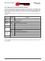
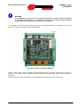
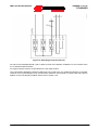
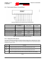
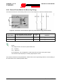
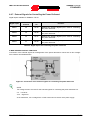
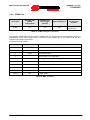
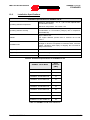
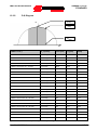
For malfunctions in serial communication affecting the COM0 and COM1 ports consult the selfdiagnosis indicator LEDs on the RS485 galvanic isolation board.
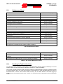
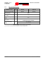
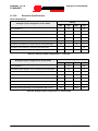
The RS485 galvanic isolation board is equipped with a total of five LEDs, three LEDs for signalling the
presence of various power supply voltages for the board itself and two LEDs for indicating fault conditions
concerning the RS485 signals. The FAULT indication can only be considered valid if the line has been
correctly terminated, i.e. DIP-switches SW1 and SW2 are both in the ON position.
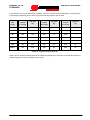
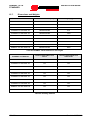
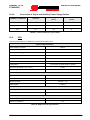
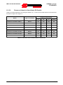
LED
Colore
Funzione
L1
Green
Supply voltage [5 V] detected for inverter side RS485 circuits
L2
Green
Inverter supply voltage [9 V] detected
L3
Green
Supply voltage [5 V] detected for Master side RS485 circuits
L5
Red
Inverter side RS485 signal faults
L6
Red
COM0 or COM1 port side RS485 signals fault
Table 39: RS485 galvanic isolation board self-diagnosis LEDs
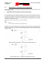
Fault conditions may be due to one of the following:
•
Differential voltage between A and B below 450 mV.
•
A or B exceed the common mode voltage range [-7 V; 12 V].
•
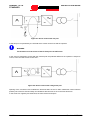
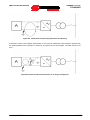
A or B connected to a fixed voltage (this condition can only be detected when communication has
been established).
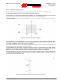
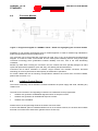
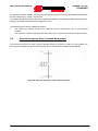
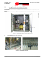
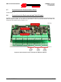
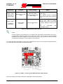
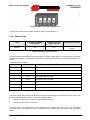
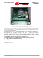
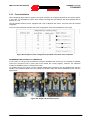
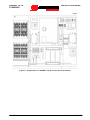
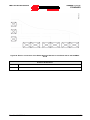
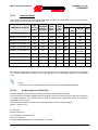
Please refer to Figure 53: Position of LEDs and DIP-switches for the location of the indicator LEDs and the
configuration DIP-switches.
11.4.2.
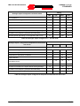
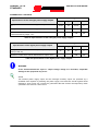
Ethernet Communication Problems
•
Check that all the programming parameters are correct.
•
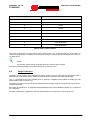
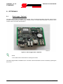
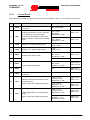
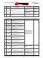
Check the Ethernet port self-diagnosis LEDs on the Data Logger board.
128/171
Rev. 04 - 03/07/2013