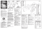
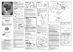
1
GET REAL PAINTBALL
A Division of A.T. Systems, Inc.
OWNER’S MANUAL
11611 Jay Street
Minneapolis, MN 55448
1-800-594-3467
(763) 767-7064
Fax: (763) 772-0603
www.getrealpaintball.com
A.T. Systems, Inc. Owner’s Manual
www.adtacsys.com
www.getrealpaintball.com
© A.T. Systems, Inc., 2002
Customer Service: (800) 594-3467
(763) 767-7064
Thank you for purchasing an AT-Series Paintball Gun!
All of us at A.T. Systems, Inc. are proud of our commitment to quality products and
customer service. The major components and features of your gun are shown in the video
that was included with your package. Please become familiar with these features and the
cautions associated with your purchase by viewing the video before attempting to operate
your gun.
If you did not receive a video, or have any other questions,
please call customer service at 1-800-594-3467.
AT-Series Paintball Guns
AT10
AT85
AT4
AT16
A.T. Systems, Inc. Owner’s Manual
www.adtacsys.com
www.getrealpaintball.com
© A.T. Systems, Inc., 2002
Customer Service: (800) 594-3467
(763) 767-7064
TABLE OF CONTENTS
I. RETURNS AND SHIPPING INFORMATION .........................................1
RETURN POLICY ................................................................................................................1
IMPORTANT INFORMATION FOR YOUR PROTECTION ..........................................................1
VISIBLE DAMAGE OR SHORTAGE.......................................................................................1
CONCEALED DAMAGE .......................................................................................................1
II. SAFETY ....................................................................................................................2
WARNINGS.........................................................................................................................2
III. OPERATION .......................................................................................................3
START UP ..........................................................................................................................3
USE OF THE GUN................................................................................................................5
SHUT DOWN ......................................................................................................................6
IV. CHAIN OF EVENTS ........................................................................................7
CYCLE CHAIN OF EVENTS..................................................................................................7
SIMULTANEOUS LOADING..................................................................................................9
FIRING MODE SELECTION................................................................................................11
V. MAINTENANCE SCHEDULE ......................................................................13
TOOLS REQUIRED ............................................................................................................13
BARREL AND UNI- SIZER...................................................................................................14
RECEIVER ........................................................................................................................15
MAGAZINE.......................................................................................................................17
GUIDE P LATE...................................................................................................................19
REAR HOUSING................................................................................................................21
VI. TROUBLESHOOTING .................................................................................28
AIR LEAKS.......................................................................................................................28
DEAD TRIGGER................................................................................................................29
STALL ..............................................................................................................................30
LOW VELOCITY ...............................................................................................................32
PAINTBALLS BREAKING IN THE GUN ...............................................................................33
MULTIPLE SHOTS IN S EMI-AUTOMATIC MODE................................................................34
MAGAZINES .....................................................................................................................34
GOOD P RACTICES AND THINGS TO KNOW .......................................................................35
A.T. Systems, Inc. Owner’s Manual
www.adtacsys.com
www.getrealpaintball.com
ii
© A.T. Systems, Inc., 2002
Customer Service: (800) 594-3467
(763) 767-7064
VII. PART LISTS AND DRAWINGS ...............................................................37
COMPLETE AT10 PAINTBALL G UN ...............................................................................37
BASE AT10 GUN .............................................................................................................38
RECEIVER, SHORT VERSION.............................................................................................39
COMPLETE AT85 PAINTBALL G UN ...............................................................................40
BASE AT85 GUN .............................................................................................................41
RECEIVER FOR AT85.......................................................................................................42
COMPLETE AT4 PAINTBALL G UN .................................................................................43
BASE AT4 GUN ...............................................................................................................44
TACTICAL RECEIVER FOR AT4........................................................................................45
COMPLETE AT16 PAINTBALL G UN ...............................................................................46
BASE AT16 GUN .............................................................................................................47
TACTICAL RECEIVER FOR AT16 ......................................................................................48
REAR HOUSING ASSEMBLY .............................................................................................49
REAR HOUSING WITH BONDED COMPONENTS .................................................................51
MAGAZINE ASSEMBLY ....................................................................................................52
MAGAZINE LEFT ASSEMBLY............................................................................................53
MAGAZINE RIGHT ASSEMBLY .........................................................................................54
LOADER ASSEMBLY.........................................................................................................55
BOLT ASSEMBLY .............................................................................................................56
HAMMER ASSEMBLY .......................................................................................................57
PISTON ASSEMBLY...........................................................................................................58
CYCLE ASSEMBLY ...........................................................................................................59
MAIN VALVE ASSEMBLY.................................................................................................60
COUPLING ASSEMBLY......................................................................................................61
TRIGGER ASSEMBLY........................................................................................................62
SIGHT ASSEMBLY ............................................................................................................63
SLEEVE ASSEMBLY..........................................................................................................64
A.T. Systems, Inc. Owner’s Manual
www.adtacsys.com
www.getrealpaintball.com
iii
© A.T. Systems, Inc., 2002
Customer Service: (800) 594-3467
(763) 767-7064
I.
RETURNS AND SHIPPING INFORMATION
Return Policy
♦ No returns are permitted without authorization from our office. Call 1-800-594-3467
to discuss your return between the hours of 8 a.m. and 5 p.m. Central Standard Time,
before returning your products.
♦ No returns will be accepted after 30 days from shipment date from A.T. Systems.
♦ Unauthorized returns will not be accepted and will be returned to sender.
♦ There is a 15% restocking charge on all returned items, plus any shipping costs
incurred.
♦ No returns are accepted on used merchandise. Used merchandise means that the
product has been handled by the customer in any way other than for inspection of the
merchandise. Once a return has been authorized, items will only be accepted if they
are in the original manufacturer’s packaging, with all manufacturer’s printed material
and accessory components included.
♦ All paintball gun warranty repairs are covered within the 90-day warranty period.
Call A.T. Systems, Inc. for more information on paintball gun service.
Important Information for Your Protection
This shipment was packed and thoroughly inspected prior to leaving our premises. By
accepting this shipment, the shipping entity acknowledges that the shipment was
delivered to them in good condition and was properly packaged. Any loss or damage that
occurs to this shipment is the sole responsibility of the shipping entity.
Visible Damage or Shortage
If the shipment you receive is visibly damaged, or if the number of cartons does not
correspond with the delivery receipt, have the delivery agent note the discrepancy or the
extent of damages on the delivery receipt. You must file a claim with the carrier
immediately upon receipt.
Concealed Damage
If damage is not noticed until after the carton is unpacked, notify the shipping entity
immediately and insist upon an inspection. This notification must be made within 15 days
of the receipt of the shipment. Retain the carton and packaging materials until the
shipment is inspected and the claim is settled.
A.T. Systems, Inc. accepts no responsibility for merchandise that is damaged in
transit. Claims for loss or damage must not be deducted from our invoice, nor
payment withheld, pending settlement of your claim.
A.T. Systems, Inc. Owner’s Manual
www.adtacsys.com
www.getrealpaintball.com
1
© A.T. Systems, Inc., 2002
Customer Service: (800) 594-3467
(763) 767-7064
II.
SAFETY
Congratulations on your purchase of an AT Series paintball gun from
A.T. Systems, Inc.!
Warnings
♦ Please remember that your gun is not a toy. Adult supervision is required for anyone
under 18 years of age to use this gun.
♦ Your gun can be considered a dangerous weapon if mishandled, abused, tampered
with, or not operated according to instructions.
♦ Misuse or careless use may cause serious injury or death.
♦ Everyone involved in paintball activities should wear appropriate protective
equipment. At a minimum, this should include approved eye, face and ear protection.
♦ Your gun may be dangerous up to 750 feet. It is not intended to be fired at velocities
higher than 300 feet per second, or at targets closer than 15 feet.
♦ As with any firearm, never point your gun toward anything that you do not intend to
hit, regardless of whether the gun is unloaded, uncharged or in the Safety Position.
♦ Any attempt to modify or service your gun other than what is authorized in this
owner’s manual may cause your gun to malfunction or to become unsafe.
♦ Any unauthorized modification or service will void your warranty.
♦ A.T. Systems, Inc. assumes no liability for the resale or safe handling of its products,
nor does A.T. Systems, Inc. assume responsibility for personal injury or property
damage resulting from the use of its products.
A.T. Systems, Inc. Owner’s Manual
www.adtacsys.com
www.getrealpaintball.com
2
© A.T. Systems, Inc., 2002
Customer Service: (800) 594-3467
(763) 767-7064
III. OPERATION
Start Up
Caution: Please watch the enclosed video before attempting to operate your gun.
1. Put the selector switch in the Safe Position.
2. Apply three drops of oil to the tank o-ring and port in air source adapter.
3. Attach the air source.
Screw tank onto the gun, until a “pop” is heard.
Then turn an extra quarter turn, or until it stops.
A.T. Systems, Inc. Owner’s Manual
www.adtacsys.com
www.getrealpaintball.com
3
© A.T. Systems, Inc., 2002
Customer Service: (800) 594-3467
(763) 767-7064
4. Load and index the magazine with no more than 20 paintballs.
Index Window
5. Insert the magazine into the gun.
6. Attach forward loader for AT85.
7. The gun is now ready to operate.
A.T. Systems, Inc. Owner’s Manual
www.adtacsys.com
www.getrealpaintball.com
4
© A.T. Systems, Inc., 2002
Customer Service: (800) 594-3467
(763) 767-7064
Use of the Gun
1. Everyone involved in paintball activities should wear appropriate protective
equipment. At a minimum, this should include approved eye, face and ear protection.
2. Never point your gun at anyone or anything that you do not want to hit.
3. If your gun misfires or stalls, do not attempt to reset the gun while the magazine is
installed as this could cause damage. Instead, remove the magazine from the gun
before attempting to reset.
4. Never insert a magazine into the gun if the magazine is not properly indexed.
5. Use only the air source for which your gun is configured. A.T. Systems, Inc. guns are
set up to run with compressed air (HPA).
AT85 only: The 50-round forward loader may require an occasional rocking motion
to allow paintballs to flow more freely into the magazine.
AT85
6. Always keep the selector in the Safe Position until you are ready to shoot the gun.
A.T. Systems, Inc. Owner’s Manual
www.adtacsys.com
www.getrealpaintball.com
5
© A.T. Systems, Inc., 2002
Customer Service: (800) 594-3467
(763) 767-7064
Shut Down
1. Remove the magazine.
2. Point in safe direction and pull the trigger to discharge the loaded round.
3. Remove the air source.
4. Pull the trigger again to disengage the internal mechanisms of the gun.
5. Put the selector in the Safe Position.
6. Your gun is now shut down.
A.T. Systems, Inc. Owner’s Manual
www.adtacsys.com
www.getrealpaintball.com
6
© A.T. Systems, Inc., 2002
Customer Service: (800) 594-3467
(763) 767-7064
IV. CHAIN OF EVENTS
This chain of event section will assume that the user has already loaded this product with
a quantity of paintballs filling both the primary forward loader and magazine (cassette
and transport mechanism).
Note: Paintballs are constantly being renewed into the transport mechanism
(cassette) from the forward primary magazine (loader).
Cycle Chain of Events
1. Firing of the unit is accomplished by pulling the trigger. However, this assumes that
the Selector is in one of the two firing modes (Semi-Automatic or Fully Automatic).
Note: Selective functions and positions will be covered in a later section.
2. When the Trigger is pulled, the Pawl is forced upward against the bottom of the Sear.
This causes the Sear to rotate, causing a disengagement of the Hammer Assembly
from the Bolt.
3. Upon disengagement, the Hammer Assembly is fired rearward where it first comes
into contact with the Valve Tube.
4. This releases a rapid pulse of high-pressure gas, thereby ejecting the paintball housed
within the Breech Sleeve through the Barrel. Note: After the paintball has left the
Barrel, the Striker continues rapidly traveling rearward. The Striker then comes
into contact with a protruding cam portion of the Rocker, which urges the
Rocker into a rotational motion.
5. This rotational motion is resisted by the Follower. The Follower is an over-center
cam acting against a protruding cam on the Rocker by means of a coil Compression
Spring.
6. Once the protruding cam on the Rocker rotates past the center peak of the Follower,
the Follower forces the Rocker to continue rotating as far as it will go (to a stop point
within the Follower cavity).
7. At this point, a cam protrusion on the Rocker will urge forward a flange on the Cycle
Core. When this happens, the Cycle Core is urged to a new position where it is
stopped from further forward motion by the Retainer.
8. The reduced pressure gas that is coming from the low-pressure side of the Regulator
Assembly that is contained in the Central Spool Area is redirected to Ports.
A.T. Systems, Inc. Owner’s Manual
www.adtacsys.com
www.getrealpaintball.com
7
© A.T. Systems, Inc., 2002
Customer Service: (800) 594-3467
(763) 767-7064
9. When gas is redirected into Ports, it is directed into the Annular Port and then
through an orifice into Area Cylinder Front. This causes the Piston Assembly to be
urged rearward in the Cylinder.
10. The Piston Assembly is attached to the Bolt and is also urged rearward toward the
Hammer Assembly, which is at rest upon the Valve Tube. Note: A coil compression
spring lies between the Bolt and Hammer Assembly.
11. As the Sear latches over the rear lip of the Bolt, the rearward motion of this entire
assembly is suddenly and automatically reversed to forward motion by way of the
Timing Collar coming into contact with a cam protrusion on the Rocker.
12. As the Rocker reverses direction and overcomes the center point of the Follower, the
Rocker is forced to continue rotation. This causes protruding cams on the Rocker to
strike rearward flange on the Cycle Core causing the Cycle Core to urge rearward to a
stop position within the Rear Housing.
13. At this time, low-pressure gas from the Area is redirected into Ports. This directs
low-pressure gas from the Area into the Annular Port Area and through an orifice
into the rear portion of the Cylinder Chamber causing the Piston Assembly to be
urged and held forward.
A.T. Systems, Inc. Owner’s Manual
www.adtacsys.com
www.getrealpaintball.com
8
© A.T. Systems, Inc., 2002
Customer Service: (800) 594-3467
(763) 767-7064
Simultaneous Loading
1. As the Piston Assembly was in rearward motion, a simultaneous automatic loading
operation was taking place at the forward end of the Piston Assembly. At the forward
end of the Piston Assembly is the Coupling.
2. The Coupling is attached by a depressible Coupling Pin to the Cog Assembly. When
the Piston Assembly is traveling rearward, the Cog Pull is also pulled rearward along
a Guide Way.
3. At this time, please note the Side Cover Assembly. Also reference the Guide Leaf and
Cog Pin. Please note that the Guide Leaf is permanently installed into the Side Cover
so that the Side Cover Assembly is made up of parts. Also note the position of the
Cog Pin for future reference. Note: the Cog Pin is permanently installed into the
Cog.
4. As the Cog Pull is traveling rearward, the protruding pins of the Cog Pull cause the
Cog to travel in a downward motion. The Cog is prevented from traveling rearward
because of the fact that the permanently attached Cog Pin is resting against the
forward face of the Guide Leaf. The downward motion is accomplished by the
protruding pins of the Cog Pull interacting with the cam slots of the Cog causing a
downward motion of the Cog until it reaches the point at which both the Cog Pin is
not restricted by the Guide Leaf and the protruding pins of the Cog Pull reach the end
of the cam stroke of the cam slots of the Cog.
5. At this point, the teeth of the Cog engage with rungs of the Conveyor Chain.
6. The Piston Assembly, Cog Pull and Cog all continue their rearward motion and
simultaneously at this time begin transport motion of the Chain.
7. Cantilevered lugs are then mounted onto the Chain at six link intervals. On these
cantilevered lugs are permanently mounted soft molded cushions. In between these
cushions are paintballs that are contained within an L-shaped track.
8. The upward traveling side of the Chain is on the left.
9. As the Piston Assembly travels further rearward and the Chain is engaged into the
Cog, a paintball will travel vertically into the Breech Staging area above the Cassette
and behind the Barrel.
10. As the Bolt is traveling rearward, the timing is such that a paintball is able to come to
rest in front of the Bolt without coming into hard contact at a high velocity with any
hard portions of the Bolt. Note: when the Chain is transporting a paintball
vertically into the Breech Staging position, a paintball has to overcome the slight
force exerted sideways onto the paintball by the Spring Guide.
A.T. Systems, Inc. Owner’s Manual
www.adtacsys.com
www.getrealpaintball.com
9
© A.T. Systems, Inc., 2002
Customer Service: (800) 594-3467
(763) 767-7064
11. As the paintball travels above the center line relationship between the paintball and
the inward protruding radius of the Spring Guide, the Spring Guide is urged inward
by means of its own spring tension. This ensures the center line location of the
paintball in the Breech Staging area wherein the paintball has no choice but to rest on
the top portion of the relaxed Spring Guide.
12. At this time, the Chain has fully accomplished a transport of distance of exactly six
links when the Piston Assembly has reached the end of its rearward stroke.
13. Exact chain indexing location is ensured by means of detents that are located 120
degrees apart on the underside of the Indexer. Also note that proper tension is
attained by a Tensioner Assembly.
Note: As a paintball is transported and loaded into the Breech Staging area forward
of the Bolt while the Bolt is traveling rearward, the paintball’s upward motion is
rapidly decelerated gently by means of a resilient cushion Sleeve Pad that is
mounted into the upper forward portion of the Sleeve.
14. As the Piston Assembly and Bolt travel forward, loading the paintball into the Breech
Staging area, guide slots of the Cog are free to disengage from the protruding pins on
the Cog Pull. This leaves the teeth portion of the Cog free to ride out of lugs of the
Chain and free to travel further forward.
15. As the entire assembly is traveling forward, the Cog Pin is riding on the upward side
of the Guide Leaf.
16. As the Cog Pin reaches the looped end portion of the Guide Leaf, the Guide Leaf
deflects downward by force of the Cog Pin until the Cog Pin travels forward to a
point allowing the forward portion of the Guide Leaf to spring back upward into a
resting position, thus completing one cycle in preparation for firing.
A.T. Systems, Inc. Owner’s Manual
www.adtacsys.com
www.getrealpaintball.com
10
© A.T. Systems, Inc., 2002
Customer Service: (800) 594-3467
(763) 767-7064
Firing Mode Selection
1. Safe Position
a. With the Safe Position of the Selector where the Select Lever is horizontally
facing the rear, the Safety is forced rearward by means of the Selector not
allowing the Forward Nose of the Safety to protrude into exposed Safety Slots in
the Selector. Note: Vertical detail on the Pawl is always urged rearward by
the Pawl Spring. This causes the rear vertical surface of the Pawl to rest on
the protruding face of the Safety so that when the Trigger is pulled, the Pawl
is guided behind the Sear. This prevents the Hammer Assembly from being
disengaged with the Bolt, thereby disabling the firing mechanism.
2. Semi-Automatic Position
a. With the Semi-Automatic position of the Selector where the Select Lever is
diagonally facing downward at a 45 degree angle toward the rear, if the Trigger is
pulled, the Pawl is in a position so that it will force the Sear to disengage the
Hammer Assembly from the Bolt, thereby firing and cycling the unit.
b. While the Trigger remains to be pulled, the unit has rapidly repeated one cycle
and as the Hammer Assembly is traveling forward, the diagonal portion of the
lower lobe of the Sear comes into contact with the upper rear radius of the Pawl.
This causes the vertical portion of the Pawl to rotate into the clearance cavity
Area of the Selector. Note: Because of the fact that the Pawl is only slightly
urged rearward by means of the Pawl Spring, it does not cause the
disengagement of the Sear from the Bolt. It should be noted that at this
point, the Hammer Assembly is prevented by other means from traveling any
farther forward than the position as shown.
c. As the user releases pressure on the Trigger, the Pawl is free to rotate and rest
against the Safety where it is ready, once again, to apply upward force to the Sear,
upon subsequent pulls of the Trigger.
3. Fully Automatic Position
a. With the Fully Automatic Position of the Selector where the Select Lever is at an
upward diagonal angle of 45 degrees to the rear, and as the Trigger remains to be
pulled and the Hammer Assembly and the Bolt are traveling forward, the forward
diagonal portion of the lower lobe of the Sear will come into contact with the
upper rear radius of the Pawl. This will cause the Pawl to rotate forward, coming
into contact with the Face of the Selector.
A.T. Systems, Inc. Owner’s Manual
www.adtacsys.com
www.getrealpaintball.com
11
© A.T. Systems, Inc., 2002
Customer Service: (800) 594-3467
(763) 767-7064
b. As the Hammer Assembly and Bolt continue traveling forward, the lower lobe of
the Sear is forced to rotate and disengage the Hammer from the Bolt. At the time,
while the Hammer Assembly and Bolt are still traveling in a forward motion, but
nearing the end of the cycle stroke, this causes subsequent automatic
disengagement of the Sear from the Bolt, while the Trigger remains to be pulled.
c. Automatic disengagement as described above will cease and reset to a “ready to
fire” position the moment the Trigger is released. The Pawl is in the “ready to
fire” position and will disengage the Sear from the Bolt when the Trigger is pulled
once more, causing a complete cycle.
A.T. Systems, Inc. Owner’s Manual
www.adtacsys.com
www.getrealpaintball.com
12
© A.T. Systems, Inc., 2002
Customer Service: (800) 594-3467
(763) 767-7064
V.
Item
1
2
3
4
5
MAINTENANCE SCHEDULE
Area
Barrel and Uni-sizer
Guide Plate
Magazine
Receiver
Rear Housing
Interval
Every Month or 5,000 Rounds
Every Month or 5,000 Rounds
Every Three Months or 15, 000 Rounds
Every Six Months or 30,000 Rounds
Every Month or 5,000 Rounds
Time Required
(Minutes)
2
2
3
2
5
Tools Required
Allen Wrenches:
(3/32, 5/64, 1/16 and .050)
Tooth Brush:
Squeegee:
A.T. Systems, Inc. Owner’s Manual
www.adtacsys.com
www.getrealpaintball.com
13
© A.T. Systems, Inc., 2002
Customer Service: (800) 594-3467
(763) 767-7064
Barrel and Uni-sizer
1. Unscrew barrel counter-clockwise to remove.
2. Twist uni-sizer counter-clockwise to remove it from the barrel.
3. Clean barrel bore with a squeegee or soft cloth. A clean bore should be dry, free of
debris and have a mirror-like finish.
4. Gently clean internal glands of the uni-sizer using a soft brush or rag with soap and
warm water.
Internal Glands
5. Re-assemble by screwing uni-sizer clockwise onto the barrel and the barrel clockwise
into the receiver. Caution: Use finger force. Do not over-tighten.
A.T. Systems, Inc. Owner’s Manual
www.adtacsys.com
www.getrealpaintball.com
14
© A.T. Systems, Inc., 2002
Customer Service: (800) 594-3467
(763) 767-7064
Receiver
1. Disassemble (for cleaning purposes only), otherwise, skip to 2b.
a. The magazine and rear sight must be removed first. Then remove the side screws
using a 5/64 hex key, followed by removing the top screws using a 3/32 hex key.
b. Depress and hold coupling button down (if absent, use a 5/64 hex key or smaller)
and pull rearward on rear housing.
A.T. Systems, Inc. Owner’s Manual
www.adtacsys.com
www.getrealpaintball.com
15
© A.T. Systems, Inc., 2002
Customer Service: (800) 594-3467
(763) 767-7064
2. Maintenance:
a. Wipe interior and exterior of receiver using a soft brush or rag with soap and
warm water.
b. Verify that the clip release snaps forward and holds a magazine in the gun.
c. Verify the selector only clicks into three positions (Auto, Safe, and Semi).
3. Re-assemble – Align piston coupling with slot in receiver, then insert rear housing
and sleeve. Install rear top screw first, followed by the other top and side screws.
Caution: Do not over-tighten top or side screws.
A.T. Systems, Inc. Owner’s Manual
www.adtacsys.com
www.getrealpaintball.com
16
© A.T. Systems, Inc., 2002
Customer Service: (800) 594-3467
(763) 767-7064
Magazine
1. Remove the four outer magazine screws and separate the halves.
2. Inspect all internal components and remove any dirt or debris using a dry, soft brush.
If necessary, mild soap and warm water can be used to remove build-up. Blow off
water with (low-pressure) compressed air and allow to dry. Warning: Do not use
chain lubricant or cleaners. Chain lubricant and cleaners will damage internal
components and void the warranty.
3. Inspect
a. Check that all 16 lugs are straight by observing the chain from the top and
side while turning indexer handle clockwise. Handling magazine is easier
with the cover held in place. If all 16 lugs and links are aligned properly, the
indexer handle will turn smoothly between indexed positions without binding
or dragging. If the handle turns smoothly, skip to c. If binding is noticed,
continue to b.
b. Binding is the result of a mis-aligned lug or link. To realign a lug, hold the
chain firmly against the top roll plate with thumb and realign lug with a
finger. View all sixteen lugs to make sure they are parallel to the side of the
magazine and straight across the top, as shown above.
A.T. Systems, Inc. Owner’s Manual
www.adtacsys.com
www.getrealpaintball.com
17
© A.T. Systems, Inc., 2002
Customer Service: (800) 594-3467
(763) 767-7064
c. After all the lugs have been checked for straightness, remove the cover and
observe the chain as it passes over the internal components. If a link binds at
the idler or indexer, then that link has been compressed. If the chain binds at
the top roll plate, the link is expanded. Both conditions are corrected using
fine point needle nose pliers as shown below.
•
Compressed links bind at idler and indexer.
•
Expanded links bind at top roll plate.
4. Re-install the cover and the four outer magazine screws.
If the chain still drags or binds after performing these steps, contact
A.T. Systems, Inc. at 1-800-594-3467.
A.T. Systems, Inc. Owner’s Manual
www.adtacsys.com
www.getrealpaintball.com
18
© A.T. Systems, Inc., 2002
Customer Service: (800) 594-3467
(763) 767-7064
Guide Plate
1. Remove the three guide plate screws using a 1/16 hex wrench.
2. Inspect the leaf spring. It should be straight with a triangle at one end.
Caution: Replace the guide plate every year or 60,000 rounds, or if:
A.T. Systems, Inc. Owner’s Manual
www.adtacsys.com
www.getrealpaintball.com
19
© A.T. Systems, Inc., 2002
Customer Service: (800) 594-3467
(763) 767-7064
3. Apply a light bead of grease to guide plate every 30,000 rounds.
4. Check that the cog pin is not missing or loose (using fingertips only).
5. Press the front boss all the way forward, then install greased guide plate. Caution:
Do not over-tighten screws.
A.T. Systems, Inc. Owner’s Manual
www.adtacsys.com
www.getrealpaintball.com
20
© A.T. Systems, Inc., 2002
Customer Service: (800) 594-3467
(763) 767-7064
Rear Housing
1. Sleeve maintenance:
a. Remove rear housing and sleeve from receiver (as described previously), then
turn them over.
b. Slide sleeve forward, or to the left, until it clears the groove in rear housing.
Rotate 180 degrees counter-clockwise. The sleeve should easily come off of the
piston shaft by gently jiggling the sleeve.
c. Remove the hammer, hammer spring and bolt from the sleeve. If they are still
connected, press on the end of the sear while firmly holding onto the hammer and
bolt.
d. Wipe off outside of hammer spring and bolt and the inside of the sleeve.
Thoroughly wash the hammer with soap and warm water and blow off with (lowpressure) compressed air.
e. Check that the bolt seal and sleeve pad are not loose or missing.
A.T. Systems, Inc. Owner’s Manual
www.adtacsys.com
www.getrealpaintball.com
21
© A.T. Systems, Inc., 2002
Customer Service: (800) 594-3467
(763) 767-7064
f. After thoroughly cleaning and drying, perform the following tests on the hammer:
Sear Test
Test:
Depress sear tail
then let it snap free.
Results: Sear should depress
smoothly and snap
back to starting
position.
Striker Test
Test:
Hold hammer
vertically and shake it
up and down.
Results: Striker should have
full, free motion when
shaken and the striker
should remain in the
“up” position while at
rest.
Guide Tube Test
Test:
Place bolt on a surface
with the seal facing
down. Align
hammer guide tube
with bolt, then release
the hammer.
Results: The hammer should
fully enter the bolt and
the sear should latch.
A.T. Systems, Inc. Owner’s Manual
www.adtacsys.com
www.getrealpaintball.com
22
© A.T. Systems, Inc., 2002
Customer Service: (800) 594-3467
(763) 767-7064
g. Place hammer spring over guide tube, then connect with bolt. Align sear with
feature on bolt.
h. Place the connected hammer, hammer spring and bolt into the sleeve.
i.
Press the piston shaft into the hole in the bolt as far as it will go. Rotate sleeve
180 degrees clockwise, and then slide it to the right, or rearward, into the slot in
rear housing.
j. Align piston coupling with slot in receiver, then insert rear housing and sleeve.
Install rear top screw first, followed by the other top and side screws. Caution:
Do not over-tighten top or side screws.
A.T. Systems, Inc. Owner’s Manual
www.adtacsys.com
www.getrealpaintball.com
23
© A.T. Systems, Inc., 2002
Customer Service: (800) 594-3467
(763) 767-7064
2. Clean exterior of rear housing using a dry, soft brush. Mild soap and water are
acceptable to use to remove build-up or debris. Blow-dry with (low-pressure)
compressed air.
3. Regulator maintenance
Caution: Never pressurize rear housing without all regulator
components properly installed.
Caution: Always remove pressure from rear housing before
performing regulator maintenance.
•
Always work on a clean, well-lit surface.
•
Always use oil provided by A.T. Systems, Inc. in the regulator. Using
other oils will void the warranty and may degrade internal seals and
components.
•
Before removing any regulator components, take note of the position of
the 12 o’clock mark on the regulator screw and the depth of the screw
compared to the surface of the housing. When re-assembling, it is
important to return the regulator screw to the same position and depth.
a. Remove the regulator screw with the 5/64 hex key, turning screw counterclockwise.
A.T. Systems, Inc. Owner’s Manual
www.adtacsys.com
www.getrealpaintball.com
24
© A.T. Systems, Inc., 2002
Customer Service: (800) 594-3467
(763) 767-7064
b. Remove regulator spring and piston next. The regulator piston is easily
removed by threading a top screw into the top of the piston and lifting
upward.
c. Remove the regulator sleeve next using a 3/32 hex wrench, turning it counterclockwise. To avoid stripping the part, make sure the hex wrench is fully
engaged.
d. Flip the rear housing over and shake the poppet loose from the regulator
cavity.
e. Make sure that the regulator cavity is clean. Use a cotton swab moistened
with A.T. Systems, Inc. oil to remove dirt and debris. Caution: Do not use
soap or solvents to clean regulator cavity.
f. Before re-assembling, make sure that all regulator components are clean and
free of fibers.
A.T. Systems, Inc. Owner’s Manual
www.adtacsys.com
www.getrealpaintball.com
25
© A.T. Systems, Inc., 2002
Customer Service: (800) 594-3467
(763) 767-7064
g. To re-assemble regulator:
•
Place the poppet into the regulator cavity with the seal on top and the
spring on the bottom.
•
Lubricate the regulator walls and the poppet seal with three drops of
A.T. Systems, Inc. oil.
•
Install regulator sleeve using the 3/32 hex wrench. Make sure the
wrench is fully engaged and do not over-tighten.
•
While holding the regulator piston by the top screw, apply a drop of oil
to the piston o-ring, then place it into the regulator on top of the sleeve.
•
Place the spring on top of the piston, then install the regulator screw
using a 5/64 hex wrench. Caution: Do not cross thread or force the
regulator screw. The screw should turn easily. Re-align the 12
o’clock mark to its original position and depth.
A.T. Systems, Inc. Owner’s Manual
www.adtacsys.com
www.getrealpaintball.com
26
© A.T. Systems, Inc., 2002
Customer Service: (800) 594-3467
(763) 767-7064
h. For reference, another view of the regulator system with parts enlarged is
shown below:
Caution: Never pressurize rear housing without all regulator
components properly installed.
Caution: Always remove pressure from rear housing before
performing regulator maintenance.
Figure 1
A.T. Systems, Inc. Owner’s Manual
www.adtacsys.com
www.getrealpaintball.com
27
© A.T. Systems, Inc., 2002
Customer Service: (800) 594-3467
(763) 767-7064
VI. TROUBLESHOOTING
A.T. Systems, Inc. encourages its customers NOT to try repairing their
gun beyond the steps described in this guide, unless they have received
A.T.S.-certified training.
Note: When the tank is nearly empty, it is common to hear a major leak down the
barrel of the gun. This is because there is not enough pressure from the tank to
keep the main valve closed.
Air Leaks
Air leaks may occur from within the gun, or they may occur in the regulator or rear vent
areas. Usually, leaks can be fixed by cleaning and lubricating the regulator system as
follows:
1. Remove the tank from the gun.
2. Remove the regulator outer screw. Refer to Figure 1 on previous page. Note the
scribe mark position and the depth of the screw, to enable you to return the screw to
the same position when re-assembling.
3. Remove the regulator spring.
4. Remove the regulator piston. Use one of the two screws from under the sight of the
gun to thread into the piston. Lift gently on the piston to pull it from the cavity.
5. Remove the sleeve using a 3/32-inch Allen wrench.
6. Remove the poppet assembly, check the o-ring for damage, and wipe with a soft
cloth.
7. Verify that the sleeve o-ring is not damaged.
8. Re-install the poppet, with the spring going in first.
9. Lubricate the regulator cavity with a few drops of A.T.S.-approved oil that was
supplied with your gun. DO NOT use WD40 as a lubricant.
10. Re-install the sleeve.
11. Lubricate the piston o-ring.
12. Re-install the piston, spring and outer screw.
A.T. Systems, Inc. Owner’s Manual
www.adtacsys.com
www.getrealpaintball.com
28
© A.T. Systems, Inc., 2002
Customer Service: (800) 594-3467
(763) 767-7064
Dead Trigger
A dead gun will not respond to the trigger or to the reset switch. This is most often fixed
by cleaning and lubricating the regulator system, as described in Air Leaks, steps 1-4.
If following these steps does not fix the problem, the proceeding are some other ways to
troubleshoot:
1. Check the incoming air pressure. The pressure going into the gun should be between
650 and 900 PSI. For those who don’t have a gauge on the tank regulator, replace
the tank regulator system. It may be that the regulator is faulty.
2. Check the leaf spring in the guide plate. Refer to Figure 2. Replace the guide plate if
the leaf spring is damaged.
Figure 2
3. Check the Air Source Adapter where the tank attaches to the gun. It may be plugged
with dirt or other contaminants and the hole must be free of debris to function
properly.
4. With the tank and the magazine removed from the gun, push the velocity
adjustment wrench down the barrel as far as it will go, using light pressure. This will
push the bolt to trip the rocker, if this was the cause of the problem. Warning:
Remove the velocity adjustment wrench from the barrel before pressurizing the gun.
A.T. Systems, Inc. Owner’s Manual
www.adtacsys.com
www.getrealpaintball.com
29
© A.T. Systems, Inc., 2002
Customer Service: (800) 594-3467
(763) 767-7064
Stall
The symptom of a stall is that the gun will work fine for a few shots, but then the trigger
will go dead. After resetting, the problem may remain. Before taking apart, perform the
following steps:
If you have the capability to adjust the regulated incoming pressure, reducing the pressure
will often eliminate stalling.
1. Remove the magazine and fire a round in a safe direction.
2. Install an empty magazine.
3. Put the gun in the Auto mode.
4. Pull and hold the trigger, and hit the reset as needed until the gun fires continuously.
If the problem still remains:
5. Reset the gun.
6. Adjust the velocity with the supplied wrench, as follows:
a. Insert the wrench into the barrel until it connects with the bolt head.
b. Turn counter-clockwise until the minimum position is reached.
c. Turn clockwise for at least six complete rotations.
If the problem still remains:
7. Disassemble the gun as described in the Maintenance section or as shown in the
video.
8. Remove the hammer/bolt assembly from its housing. Refer to Figure 3.
Figure 3
A.T. Systems, Inc. Owner’s Manual
www.adtacsys.com
www.getrealpaintball.com
30
© A.T. Systems, Inc., 2002
Customer Service: (800) 594-3467
(763) 767-7064
9. Holding on to both the bolt and the hammer, lift the sear to disengage the hammer.
10. Shake the hammer to assure that the striker moves freely and that the striker spring is
still attached.
11. Thoroughly clean the hammer assembly with soap and water. Then blow off with
compressed air.
12. Re-assemble the gun.
A.T. Systems, Inc. Owner’s Manual
www.adtacsys.com
www.getrealpaintball.com
31
© A.T. Systems, Inc., 2002
Customer Service: (800) 594-3467
(763) 767-7064
Low Velocity
The factory setting for the gun results in a velocity of roughly 270-300 feet per second. If
the gun performs at a lower velocity, you can do the following:
•
Verify that the velocity is adjusted properly, as described in the section titled Stall.
•
For those who have the ability to adjust the regulated incoming pressure, increasing
the pressure will increase the velocity. Velocity should never be adjusted above 300
feet per second.
If the problem still remains, perform Sleeve Maintenance as described previously or:
1. Disassemble the gun as described in the Maintenance section or as shown in the
video.
2. Remove the hammer/bolt assembly from its housing. Refer to Figure 3.
3. Holding on to both the bolt and the hammer, lift the sear to disengage the hammer.
4. Check the bolt to assure that the rubber bolt seal is still attached.
5. Check the hammer tube for burrs or residue, which may prevent the bolt from sliding
freely on the hammer tube.
6. Lubricate the entire assembly with WD40. This is the only location where WD40
should be used on the gun.
7. Shake off any excess lubricant.
8. Re-assemble the gun.
A.T. Systems, Inc. Owner’s Manual
www.adtacsys.com
www.getrealpaintball.com
32
© A.T. Systems, Inc., 2002
Customer Service: (800) 594-3467
(763) 767-7064
Paintballs Breaking in the Gun
For breakage in the barrel:
1. Verify that the velocity is adjusted properly, as described in the Low Velocity section.
2. Try new paintballs if you suspect that your supply may be old or defective.
For breakage in the breach area:
1. Remove the magazine.
2. Turn the magazine indexer crank handle clockwise to check that it doesn’t bind.
3. Check that the lugs on the chain are at 90-degree angles when viewed from the side
and top. If they aren’t, bend them into place with a small pliers, using caution to
prevent distortion of the chain (see Magazine Maintenance section).
4. Install the empty magazine in an indexed (clicked) position, and dry fire a few
rounds. Verify that the lugs actually move, and that a lug is visible in the index
window. If a lug is not visible in the index window, the magazine is mis-indexing. If
the magazine is mis-indexing, remove the guide plate (3-screw cover) and inspect the
guide plate leaf spring for damage. The spring should appear as in Figure 4. If the
leaf spring is damaged, the guide plate will need to be replaced.
Figure 4
Caution: Before re-installing the guide plate, re-pressurize the gun without the
magazine installed. This will assure that the cog is moved fully forward. Failure
to do this will cause the leaf spring to be damaged.
A.T. Systems, Inc. Owner’s Manual
www.adtacsys.com
www.getrealpaintball.com
33
© A.T. Systems, Inc., 2002
Customer Service: (800) 594-3467
(763) 767-7064
Multiple Shots in Semi-Automatic Mode
When the gun fires more than one shot on a single trigger pull in the semi-automatic
mode, the following steps should be taken:
1. Be sure the barrel is snugly hand-tightened into the receiver.
2. Remove the rear assembly from the receiver as described in the Maintenance section
or as shown in the video. Inspect the trigger assembly for a broken spring or debris in
the moving parts.
3. Remove the sleeve assembly and check to see if the outside of the sleeve has
scratches from the excessive wear near the slot. If there is excessive wear, the sleeve
should be replaced.
Magazines
Problems with the magazines can be avoided by following these steps:
1. Check the magazine for dirt and debris before loading paintballs into it. Refer to the
Maintenance section for proper cleaning of the magazine.
2. Looking into the magazine from the top, rotate the indexer handle clockwise to assure
that all 16 pins are straight out from the chain. Bent pins should be straightened with
a small needle-nose pliers, using care to prevent distortion to the chain.
3. With the magazine out of the gun, pressurize the gun. Then insert the empty
magazine and turn the indexing crank handle clockwise through all 16 positions. The
chain should turn freely, with no binding or dragging.
4. Next, dry fire the gun with the empty magazine. As the gun is firing, watch to see
that the pins index properly and always land in the index window.
5. Pre-load the magazine:
a. Using quality paintballs, feed about 10 rounds into the magazine.
b. Hold the magazine with the feed opening facing upward at an angle while
indexing the balls to the top of the magazine.
c. Feed the remaining paintballs into the opening. Using more than 20 balls in the
magazine may cause the balls to bind as the chain indexes.
d. Never force or pack paintballs into the magazine. The paintballs need to have
free movement to index properly.
A.T. Systems, Inc. Owner’s Manual
www.adtacsys.com
www.getrealpaintball.com
34
© A.T. Systems, Inc., 2002
Customer Service: (800) 594-3467
(763) 767-7064
Good Practices and Things to Know
Before pressurizing the gun:
1. Read the entire owner’s manual and view the enclosed video. This will prevent many
user-induced problems.
2. As a matter of safety, check the barrel to be sure that a ball hasn’t remained loaded in
the gun.
3. Put 4-5 drops of the supplied lubricant into the filter located in the Rear Air Source
Adapter. This will help lubricate the internal seals.
4. Put a few drops of the supplied lubricant on the tank seal to prevent it from leaking or
becoming damaged.
5. Avoid over-tightening the screws on the magazine as it could crack.
6. Always check the magazine to be sure it is properly indexed before inserting it into
the gun.
7. If you ever need to reference the serial number of your gun, it is located on the
underside of the gun, just to the rear of the grip on the rear housing.
Pressurizing the gun:
1. Do not partially unscrew the tank from a gun and then try to screw it back in. This
will almost always damage the tank o-ring. Instead, fully remove the tank, lubricate
the o-ring and then screw the tank back onto the gun.
2. Do not dry fire an AT-Series gun without a magazine inserted.
3. With an empty magazine installed, dry fire a few rounds to assure that the gun fires in
both semi-automatic and automatic modes. Watch the chain lugs or the orange
indexing insert to assure that the magazine is indexing properly.
Firing the gun:
1. It is normal for air to exhaust from the rear of the gun after each shot. A steady
stream of air when the gun is fired is considered a leak.
2. For AT85 Series guns: To keep paintballs properly fed into the chain mechanism of
the magazine, it is sometimes necessary to rock the gun in a gentle forward and rear
motion. This will allow a steady stream of balls to be fired without “blank” shots.
A.T. Systems, Inc. Owner’s Manual
www.adtacsys.com
www.getrealpaintball.com
35
© A.T. Systems, Inc., 2002
Customer Service: (800) 594-3467
(763) 767-7064
Repairing the gun:
1. Magazine note: Using chain lubricants to “help” the chain be smooth can degrade the
plastic and cause it to crack or shatter. The magazine is designed to keep up with the
gun’s high performance features, and no further modification is required.
2. When replacing a broken guide plate, remember to pressurize the gun without the
magazine inserted. Then attach the guide plate. This will locate the cog in the correct
position, and prevent the leaf spring and the magazine from being damaged.
3. A.T. Systems does not recommend that you try to repair your gun beyond what is
described in this Troubleshooting section. For guns under warranty, you run the
risk of voiding the warranty.
4. If you need to return your gun for repairs, it is necessary for you to contact A.T.
Systems before shipping it to us. Also, attach a description of the problem with your
gun. This will help us pinpoint the problem much quicker, thus we will be able to
return your gun to you sooner.
A.T. Systems, Inc. Owner’s Manual
www.adtacsys.com
www.getrealpaintball.com
36
© A.T. Systems, Inc., 2002
Customer Service: (800) 594-3467
(763) 767-7064
VII. PART LISTS AND DRAWINGS
Complete AT10 Paintball Gun
Part No.:
Description:
Item
1
N/A
N/A
2
N/A
N/A
N/A
3
N/A
N/A
N/A
N/A
Component
AT10HPA-BASE
(AT10HPAT-BASE)
(AT10-BASE)
TS1004-5RG
(TS1004-5R)
(TS1004-47R)
(TS1004)
TS1300M
(TS1300T)
(TS1300V)
(TS1300X)
(TS1300)
AT10 HPA
AT10 HPA Paintball Gun
Description
AT10HPA Gun w/o Magazine
AT10 HPAT Gun w/o Magazine
AT10 CO2 Gun w/o Magazine
13 Cubic Inch HP Tank, Reg. w/ Gauge
13 Cubic Inch HP Tank, Reg.
47 Cubic Inch HP Tank, Reg. w/ Gauge
12 oz. CO2 Tank
Magazine Assembly w/ Mylar
Tactical Magazine Assembly w/ Mylar
Viewloader Magazine Assembly
Tactical Magazine Assembly w/o Mylar
Magazine Assembly w/o Mylar
Qty Required
1
1
1
1
1
1
1
1
1
1
1
1
( ) Indicates that component is available, but not shown
A.T. Systems, Inc. Owner’s Manual
www.adtacsys.com
www.getrealpaintball.com
37
© A.T. Systems, Inc., 2002
Customer Service: (800) 594-3467
(763) 767-7064
Base AT10 Gun
Part No.:
Description:
Item
1
2
N/A
3
4
5
6
7
8
N/A
9
10
11
12
Component
TS1002
TS1100S
(TS1100ST)
TS1110S
TS1113-10
TS1160
TS1185
TS1186
TS1200H
(TS1200)
TS1207
TS1280
TS2300
TS2400
AT10HPA-BASE
AT10HPA Gun w/o Magazine
Description
Grip Label
Receiver, Short
Short Tactical Receiver for AT10
Barrel
Uni-sizer
Barrel O-ring
Top Screw
Side Screw
HPA Rear Housing Assembly
CO2 Rear Housing Assembly
Grip
Grip Screw
Sight Housing Assembly
Sleeve Assembly
Qty Required
1
1
1
1
1
1
2
2
1
1
1
1
1
1
( ) Indicates that component is available, but not shown
Available Version
Part No.:
AT10-BASE
Description:
AT10 Gun w/o Magazine
Features:
TS1100S – Short Receiver
TS1200 – CO2 Rear Housing
A.T. Systems, Inc. Owner’s Manual
www.adtacsys.com
www.getrealpaintball.com
Available Version
Part No.:
AT10HPAT-BASE
Description:
AT10HPAT Gun w/o Magazine
Features:
TS1100ST – Short Tactical
Receiver
TS1200H – HPA Rear Housing
38
© A.T. Systems, Inc., 2002
Customer Service: (800) 594-3467
(763) 767-7064
Receiver, Short Version
Part No.:
Description:
Item
1
2
3
4
5
6
7
N/A
8
9
10
11
12
13
14
15
16
17
18
N/A
19
20
21
22
Component
TS1005
TS1101
**TS1101-3
TS1101-4
TS1101-5
TS1102
**TS1105-3
(TS1105-T)
TS1106
TS1107
TS1114
**TS1117
TS1120
TS1121
TS1130
TS1150
TS1152
**TS 1154
TS1180
(TS1180)
TS1181
TS1190
TS1191
TS1863
TS1100S
Receiver, Short Version
Description
Red Dot
Receiver
Button Cover
Receiver Plate
Barrel Adapter
Guide Plate
Selector 3 Position
Selector, Tactical
Clip Re lease Outer
Clip Release Inner
Cog Pull
Coupling Button
Cog
Cog Clip
Chrome Steel Ball
Selector Spring
Clip Release Spring
Button Spring
Side Cover Screw
Magazine Reversal Lock-out
Clip Release Screw
Selector Shaft
Selector Retainer Pin
Cycle Spool Dampener
Qty Required
1
1
1
1
1
1
1
1
1
1
1
1
1
1
1
1
1
1
3
1
1
1
1
3
( ) Available on TS1100ST only
** Available on TS1100S only
Available Version
Part No.:
TS1100ST
Description:
Receiver, Short Tactical
Features:
3-Position Tactical Selector
Magazine Reversal Lock-out
De-Coupling Port
A.T. Systems, Inc. Owner’s Manual
www.adtacsys.com
www.getrealpaintball.com
39
© A.T. Systems, Inc., 2002
Customer Service: (800) 594-3467
(763) 767-7064
Complete AT85 Paintball Gun
Part No.:
Description:
Item
1
N/A
N/A
2
N/A
N/A
N/A
3
N/A
N/A
N/A
N/A
4
Component
AT85HPA-BASE
(AT85HPAT-BASE)
(AT85-BASE)
TS1004-47R
(TS1004-5RG)
(TS1004-5R)
(TS1004)
TS1300
(TS1300T)
(TS1300V)
(TS1300X)
(TS1300M)
TS1090
AT85 HPA
AT85 HPA Paintball Gun
Description
AT85 HPA Gun w/o Magazine
AT85 HPAT Gun w/o Magazine
AT85 CO2 Gun w/o Magazine
47 Cubic Inch HP Tank, Reg. w/ Gauge
13 Cubic Inch HP Tank, Reg. w/ Gauge
13 Cubic Inch HP Tank, Reg.
12 oz. CO2 Tank
Magazine Assembly
Tactical Magazine Assembly w/ Mylar
Viewloader Magazine Assembly
Tactical Magazine Assembly w/o Mylar
Magazine Assembly w/ Mylar
Bottom Line Adapter Kit
Qty Required
1
1
1
( ) Indicates that component is available, but not shown
A.T. Systems, Inc. Owner’s Manual
www.adtacsys.com
www.getrealpaintball.com
40
© A.T. Systems, Inc., 2002
Customer Service: (800) 594-3467
(763) 767-7064
Base AT85 Gun
Part No.:
Description:
Item
1
2
N/A
3
4
5
6
7
8
N/A
9
10
11
12
13
Component
TS1002
TS1100
(TS1100T85)
TS1110
TS1113-10
TS1160
TS1185
TS1186
TS1200-H
(TS1200)
TS1207
TS1280
TS1400
TS2300
TS2400
AT85HPA-BASE
AT85HPA Gun w/o Magazine
Description
Grip Label
Receiver Assembly
Tactical Receiver for AT85
Barrel
Uni-sizer
Barrel O-ring
Top Screw
Side Screws
HPA Rear Housing Assembly
CO2 Rear Housing Assembly
Grip
Grip Screw
Loader Assembly
Sight Housing Assembly
Sleeve Assembly
Qty Required
1
1
1
1
1
2
2
1
1
1
1
1
1
( ) Indicates that component is available, but not shown
Available Version
Part No.:
AT85HPAT-BASE
Description:
AT85HPAT Gun w/o Magazine
Features:
TS1100T85 – Tactical Receiver
TS1200H – HPA Rear Housing
A.T. Systems, Inc. Owner’s Manual
www.adtacsys.com
www.getrealpaintball.com
Available Version
Part No.:
AT85-BASE
Description:
AT85 Gun w/o Magazine
Features:
TS1100 – Receiver
TS1200 – CO2 Rear Housing
41
© A.T. Systems, Inc., 2002
Customer Service: (800) 594-3467
(763) 767-7064
Receiver for AT85
Part No.:
Description:
Item
1
2
3
4
5
N/A
6
7
8
9
10
11
12
13
14
15
16
17
18
19
N/A
20
21
22
23
24
Component
TS1005
TS1101
**TS1101-3
TS1102
**TS1105-3
(TS1105-T)
TS1106
TS1107
TS1108
TS1109
TS1114
**TS1117
TS1120
TS1121
TS1130
TS1150
TS1151
TS1152
**TS1154
TS1180
(TS1180)
TS1181
TS1182
TS1190
TS 1191
TS1863
TS1100
Receiver for AT85
Description
Red Dot
Receiver
Button Cover
Guide Plate
Selector 3 Position
Selector - Tactical
Clip Release Outer
Clip Release Inner
Forend
Loader Latch
Cog Pull
Coupling Button
Cog
Cog Clip
Chrome Steel Ball
Selector Spring
Latch Spring
Clip Release Spring
Button Spring
Side Cover Screw
Magazine Reversal Lock-out
Clip Release Screw
Loader Latch Screw
Selector Shaft
Selector Retainer Pin
Cycle Spool Dampener
Qty Required
1
1
1
1
1
1
1
1
1
1
1
1
1
1
1
1
1
1
3
1
1
1
1
1
3
( ) Available on TS1100T85 only
** Available on TS1100 only
Available Version
Part No.:
TS1100T85
Description:
Tactical Receiver for AT85
Features:
3-Position Tactical Selector, Magazine Reversal Lock-out,
De-coupling Port
A.T. Systems, Inc. Owner’s Manual
www.adtacsys.com
www.getrealpaintball.com
42
© A.T. Systems, Inc., 2002
Customer Service: (800) 594-3467
(763) 767-7064
Complete AT4 Paintball Gun
Part No.:
Description:
Item
1
2
N/A
3
N/A
N/A
N/A
N/A
Component
AT4-BASE
TS1004-5RG
(TS1004-47R)
TS1300M
(TS1300T)
(TS1300V)
(TS1300X)
(TS1300)
AT4
AT4 Paintball Gun
Description
AT4 Gun w/o Magazine
13 Cubic inch HP Tank, Reg. w/ Gauge
47 Cubic Inch HP Tank, Reg w. Gauge
Magazine Assembly w/ Mylar
Tactical Magazine Assembly w/ Mylar
Viewloader Magazine Assembly
Tactical Magazine Assembly w/o Mylar
Magazine Assembly w/o Mylar
Qty Required
1
1
1
( ) Indicates that component is available, but not shown
A.T. Systems, Inc. Owner’s Manual
www.adtacsys.com
www.getrealpaintball.com
43
© A.T. Systems, Inc., 2002
Customer Service: (800) 594-3467
(763) 767-7064
Base AT4 Gun
Part No.:
Description:
Item
1
2
3
4
5
6
7
8
9
10
11
Component
TS1100T4
TS1110-5
TS1113-1
TS1126
TS1160
TS1185
TS1186
TS1200T
TS1207
TS1280
TS2400
A.T. Systems, Inc. Owner’s Manual
www.adtacsys.com
www.getrealpaintball.com
AT4 - Base
AT4 Gun w/o Magazine
Description
Tactical Receiver, AT4
Barrel, 16”
Uni-sizer
Handle, Tactical
Barrel O-ring
Top Screw
Side Screws
Tactical Rear Housing
Grip
Grip Screw
Sleeve Assembly
44
Qty Required
1
1
1
1
1
2
2
1
1
1
1
© A.T. Systems, Inc., 2002
Customer Service: (800) 594-3467
(763) 767-7064
Tactical Receiver for AT4
Part No.:
Description:
Item
1
2
3
4
5
6
7
8
9
10
11
N/A
12
13
14
15
16
17
18
19
20
21
22
23
24
25
26
27
28
Component
TS1005
TS1101
TS1101-11
TS1101-4
TS1101-7
TS1101-8
TS1101-9
TS1102
TS1103
TS1103-1
TS1105-T
(TS1105-3)
TS1106
TS1107
TS1114
TS1120
TS1121
TS1125
TS1130
TS1150
TS1152
TS1180
TS1181
TS1183
TS1190
TS1191
TS1194
TS1290
TS1863
TS1100T4
Tactical Receiver for AT4
Description
Red Dot
Receiver
Barrel Sleeve, AT4
Receiver Plate
Flat Top Rail
Slip Ring
Foremount
Guide Plate
Handguard Cap, AT4
Handguard Set
Selector, Tactical
Selector, 3-Position
Clip Release Outer
Clip Release Inner
Cog Pull
Cog
Cog Clip
Sight, Tactical
Chrome Steel Ball
Selector Spring
Clip Release Spring
Side Cover Screw
Clip Release Screw
Tactical Sight Set Screw
Selector Shaft
Selector Retainer Pin
Sight Blade Shaft
Trigger Pin
Cycle Spool Dampener
Qty Required
1
1
1
1
1
1
1
1
1
1
1
1
1
1
1
1
1
1
1
1
4
1
1
1
1
2
1
3
( ) Indicates that component is available, but not shown
A.T. Systems, Inc. Owner’s Manual
www.adtacsys.com
www.getrealpaintball.com
45
© A.T. Systems, Inc., 2002
Customer Service: (800) 594-3467
(763) 767-7064
Complete AT16 Paintball Gun
Part No.:
Description:
Item
1
2
N/A
3
N/A
N/A
N/A
N/A
Component
AT16-BASE
TS1004-5RG
(TS1004-47R)
TS1300M
(TS1300T)
(TS1300V)
(TS1300X)
(TS1300)
AT16
AT16 Paintball Gun
Description
AT16 Gun w/o Magazine
13 Cubic inch HP Tank, Reg. w/ Gauge
47 Cubic Inch HP Tank, Reg w. Gauge
Magazine Assembly w/ Mylar
Tactical Magazine Assembly w/ Mylar
Viewloader Magazine Assembly
Tactical Magazine Assembly w/o Mylar
Magazine Assembly w/o Mylar
Qty Required
1
1
1
( ) Indicates that component is available, but not shown
A.T. Systems, Inc. Owner’s Manual
www.adtacsys.com
www.getrealpaintball.com
46
© A.T. Systems, Inc., 2002
Customer Service: (800) 594-3467
(763) 767-7064
Base AT16 Gun
Part No.:
Description:
Item
1
2
3
4
5
6
7
8
9
10
11
Component
TS1100T16
TS1110-5
TS1113-1
TS1126
TS1160
TS1185
TS1186
TS1200T
TS1207
TS1280
TS2400
A.T. Systems, Inc. Owner’s Manual
www.adtacsys.com
www.getrealpaintball.com
AT16 - Base
AT16 Gun w/o Magazine
Description
Tactical Receiver, AT16
Barrel, 23”
Uni-sizer
Handle, Tactical
Barrel O-ring
Top Screw
Side Screws
Tactical Rear Housing
Grip
Grip Screw
Sleeve Assembly
47
Qty Required
1
1
1
1
1
2
2
1
1
1
1
© A.T. Systems, Inc., 2002
Customer Service: (800) 594-3467
(763) 767-7064
Tactical Receiver for AT16
Part No.:
Description:
Item
1
2
3
4
5
6
7
8
9
10
11
N/A
12
13
14
15
16
17
18
19
20
21
22
23
24
25
26
27
28
Component
TS1005
TS1101
TS1101-12
TS1101-4
TS1101-7
TS1101-8
TS1101-9
TS1102
TS1103-16
TS1103-2
TS1105-T
(TS1105-3)
TS1106
TS1107
TS1114
TS1120
TS1121
TS1125
TS1130
TS1150
TS1152
TS1180
TS1181
TS1183
TS1190
TS1191
TS1194
TS1290
TS1863
TS1100T16
Tactical Receiver for AT16
Description
Red Dot
Receiver
Barrel Sleeve, AT16
Receiver Plate
Flat Top Rail
Slip Ring
Foremount
Guide Plate
Handguard Cap, AT16
Handguard Set, AT16
Selector, Tactical
Selector, 3-Position
Clip Release Outer
Clip Release Inner
Cog Pull
Cog
Cog Clip
Sight, Tactical
Chrome Steel Ball
Selector Spring
Clip Release Spring
Side Cover Screw
Clip Release Screw
Tactical Sight Set Screw
Selector Shaft
Selector Retainer Pin
Sight Blade Shaft
Trigger Pin
Cycle Spool Dampener
Qty Required
1
1
1
1
1
1
1
1
1
1
1
1
1
1
1
1
1
1
1
1
4
1
1
1
1
2
1
3
( ) Indicates that component is available, but not shown
A.T. Systems, Inc. Owner’s Manual
www.adtacsys.com
www.getrealpaintball.com
48
© A.T. Systems, Inc., 2002
Customer Service: (800) 594-3467
(763) 767-7064
Rear Housing Assembly
Part No.:
Description:
Item
1
2
3
4
5
6
N/A
N/A
7
8
9
10
11
12
13
14
15
16
17
18
19
20
21
22
23
24
25
26
27
28
N/A
29
30
31
Component
TS1201
TS1204
TS1205
TS1206
TS1208
**TS1210-2
*TS1210-1
***TS1210
TS1212
TS1213
TS1214
TS1215
TS1216
RS1219
TS1220
***TS1221
TS1252
TS1253
TS1254
TS1255
TS1260
TS1261
TS1262
TS1264
TS1267
TS1284
TS1290
TS1292
TS1700
TS1800A
***TS1800X
TS1900
TS1950
TS2200
TS1200H
HPA Rear Housing Assembly
Description
Rear Housing + Bonded Components
Rocker
Follower
Reset
Safety
Rear Air Source Adapter for HPA
Air Source Adapter, Tactical
Rear Air Source Adapter
Valve Screw
Regulator Piston
Regulator Screw
Regulator Sleeve
Regulator Poppet
Reset Pin
Retainer
ASA Filter
Regulator Spring
Regulator Poppet Spring
Follower Spring
Safety Spring
Regulator Poppet Seal
Adapter Seal Rear
Adapter Seal Front
Regulator Piston O-ring
Regulator Sleeve Seal
Retainer Screw
Trigger Pin
Rocker Shaft
Piston Assembly
Cycle Assembly
CO2 Cycle Assembly
Valve Tube Assembly
Valve Tube Spring
Trigger Assembly
Qty Required
1
1
1
1
1
1
1
1
1
1
1
1
1
1
1
1
1
1
1
1
1
1
1
1
1
1
1
1
1
1
1
1
1
1
* Used on TS1200T only
** Used on TS1200H only
*** Used on TS1200 only
A.T. Systems, Inc. Owner’s Manual
www.adtacsys.com
www.getrealpaintball.com
49
© A.T. Systems, Inc., 2002
Customer Service: (800) 594-3467
(763) 767-7064
Available Version
Part No.:
TS1200T
Description:
Tactical Rear Housing Assembly
Features:
Tactical ASA
No ASA Filter
A.T. Systems, Inc. Owner’s Manual
www.adtacsys.com
www.getrealpaintball.com
50
© A.T. Systems, Inc., 2002
Customer Service: (800) 594-3467
(763) 767-7064
Rear Housing with Bonded Components
Part No.:
Description:
Item
1
2
3
4
5
6
7
Component
TS1201
TS1211
TS1215-1
TS1222
TS1281
TS1286
TS1294
A.T. Systems, Inc. Owner’s Manual
www.adtacsys.com
www.getrealpaintball.com
TS1201 Bonded
Rear Housing with Bonded Components
Description
Rear Housing
Main Valve Body
Regulator Insert
Regulator Filter
Manifold Screw (LP)
Filter Backup Screw
Retainer Pin
51
Qty Required
1
1
1
1
3
1
1
© A.T. Systems, Inc., 2002
Customer Service: (800) 594-3467
(763) 767-7064
Magazine Assembly
Part No.:
Description:
Item
1
2
N/A
N/A
N/A
N/A
3
N/A
Component
TS1380
TS1398
(TS1398M)
(TS1398X)
(TS1398T)
**TS1020
TS1399T
**TS1399V
TS1300
Magazine Assembly
Description
Screw
Magazine Left Assembly
Magazine Left Assembly – Clear w/ Mylar
Magazine Left Assembly - Black
Magazine Left Assembly – Black w/ Mylar
Magazine Left, Viewloader Adapter
Tactical Magazine Right Assembly
Magazine Right Assembly for Viewloader
Qty Required
4
1
1
1
1
1
1
1
( ) Indicates that component is available, but not shown
** To be used with TS1300V - Viewloader Magazine Assembly only
Available Version
Part No.:
TS1300M, TS1300X, TS1300T and
TS1300V
Description:
Magazine Assemblies
Features:
See below
TS1300
TS1398M
Clear, with Mylar
TS1300T
TS1399T
TS1398X
Black, no Mylar
TS1300X
TS1399T
TS1398T
Black, with Mylar
TS1300T
TS1399T
**TS1399V
TS1300V
A.T. Systems, Inc. Owner’s Manual
www.adtacsys.com
www.getrealpaintball.com
52
**TS1020
Clear, with Tube
© A.T. Systems, Inc., 2002
Customer Service: (800) 594-3467
(763) 767-7064
Magazine Left Assembly
Part No.:
Description:
Item
1
N/A
N/A
N/A
2
3
Component
TS1302
(TS1302M)
(TS1302X)
(TS1302T)
TS1322
TS1371
TS1398
Magazine Left Assembly
Description
Magazine Cover Left
Magazine Cover Left, w/ Mylar
Magazine Cover Left
Magazine Cover Left, w/ Mylar
Spring Guide
Spring Guide Retainer
Qty Required
1
1
1
1
1
2
( ) Indicates that component is available, but not shown
Available Versions:
Part No.:
TS1398M, TS1398X, TS1398T and TS1020
Description:
Magazine Left Assemblies
Features:
See below
TS1398M
Clear, w/ Mylar
TS1398X
Black, w/o Mylar
TS1398T
Black, w/ Mylar
TS1020
Clear, w/ Tube
A.T. Systems, Inc. Owner’s Manual
www.adtacsys.com
www.getrealpaintball.com
53
© A.T. Systems, Inc., 2002
Customer Service: (800) 594-3467
(763) 767-7064
Magazine Right Assembly
Part No.:
Description:
Item
1
2
3
4
5
6
7
8
9
10
11
12
13.1
13.2
14
15
16
17
18
19
20
Component
TS1130
TS1291
TS1301T
TS1303
TS1303-1
TS1304
TS1306
TS1307
TS1308
TS1310
TS1311
TS1320
TS1309-1
TS1309-2
TS1350
TS1351
TS1370
TS1379
TS1382
TS1386
TS1391
A.T. Systems, Inc. Owner’s Manual
www.adtacsys.com
www.getrealpaintball.com
TS1399T
Tactical Magazine, Right
Description
Indexer Ball/Selector Ball
Pawlpin/Axle
Tactical Clip Cover Right
Indexer
Indexer Insert
Cushion
Idler
Chain Guide
Top Rollplate
Chain
Top Roll
Tensioner
Indexer Crank Base
Indexer Crank Handle
Indexer Spring
Tensioner Spring
Retaining Ring
Tensioner/Guide Washer
Tensioner/Guide Screw
Top Plate Screw
Crank Pin
54
Qty Required
1
2
1
1
1
16
1
1
1
1
2
1
1
1
1
1
1
3
3
1
1
© A.T. Systems, Inc., 2002
Customer Service: (800) 594-3467
(763) 767-7064
Loader Assembly
Part No.:
Description:
Item
1
2
3
Component
TS1401
TS1402
TS1403
A.T. Systems, Inc. Owner’s Manual
www.adtacsys.com
www.getrealpaintball.com
TS1400
Loader Assembly
Description
Forward Magazine
Forward Magazine Cap
Forward Magazine Gate
55
Qty Required
1
1
1
© A.T. Systems, Inc., 2002
Customer Service: (800) 594-3467
(763) 767-7064
Bolt Assembly
Part No.:
Description:
Item
1
2
3
4
5
6
7
8
9
10
Component
TS1501
TS1510
TS1512
TS1540
TS1560
TS1561
TS1570
TS1571
TS1572
TS1581
A.T. Systems, Inc. Owner’s Manual
www.adtacsys.com
www.getrealpaintball.com
TS1500
Bolt Assembly
Description
Bolt Front
Bolt Body
Bolt Sleeve
Bolt Washer
Bolt Nut O-ring
Bolt Seal
Bolt Nut Retainer
Bolt Washer Retainer
Bolt Sleeve Retainer
Bolt Set Screw
56
Qty Required
1
1
1
1
1
1
1
1
1
1
© A.T. Systems, Inc., 2002
Customer Service: (800) 594-3467
(763) 767-7064
Hammer Assembly
Part No.:
Description:
Item
1
2
3
4
5
6
7
8
9
Component
TS1610
TS1611
TS1612
TS1620
TS1650
TS1651
TS1690
TS1680
TS1691
A.T. Systems, Inc. Owner’s Manual
www.adtacsys.com
www.getrealpaintball.com
TS1600
Hammer Assembly
Description
Hammer Body Heat Treated
Guide Tube
Striker
Sear
Sear Spring
Striker Spring
Sear Pin/Striker Spring Pin
Striker Set Screw
Striker Pin
57
Qty Required
1
1
1
1
1
1
1
1
1
© A.T. Systems, Inc., 2002
Customer Service: (800) 594-3467
(763) 767-7064
Piston Assembly
Part No.:
Description:
Item
1
2
3
4
5
6
7
8
9
10
11
12
13
14
15
16
17
Component
TS1710
TS1711
TS1712
TS1715
TS1740
TS1742
TS1743
TS1750
TS1760
TS1761
TS1762
TS1763
TS1770
TS1771
TS1772
TS1780
TS2000
A.T. Systems, Inc. Owner’s Manual
www.adtacsys.com
www.getrealpaintball.com
TS1700
Piston Assembly
Description
Cylinder Wall
Piston Shaft
Timing Collar
Timing Collar Spacer
Piston Washer
Bulkhead Washer
Coupling Spring Washer
Coupling Spring
Piston Seal
Bulkhead Seal
Cylinder Seal Front
Cylinder Seal Rear
Cylinder Retaining Ring
Piston Retaining Ring
Coupling Spring Retainer
Timing Collar Set Screw
Coupling Assembly
58
Qty Required
1
1
1
1
2
2
2
1
1
1
1
1
1
2
2
1
1
© A.T. Systems, Inc., 2002
Customer Service: (800) 594-3467
(763) 767-7064
Cycle Assembly
Part No.:
Description:
Item
1
2
3
4
5
Component
TS1806
TS1811
TS1812
TS1864
TS1865
A.T. Systems, Inc. Owner’s Manual
www.adtacsys.com
www.getrealpaintball.com
TS1800
Cycle Assembly
Description
Bulkhead
Cycle Valve Spool
Cycle Valve Body
Cycle Outer Seal, Large
Spool Seal
59
Qty Required
1
1
1
4
2
© A.T. Systems, Inc., 2002
Customer Service: (800) 594-3467
(763) 767-7064
Main Valve Assembly
Part No.:
Description:
Item
1
2
3
4
5
6
Component
TS1910
TS1911
TS1912
TS1913
TS1960
TS1961
A.T. Systems, Inc. Owner’s Manual
www.adtacsys.com
www.getrealpaintball.com
TS1900
Valve Tube Assembly
Description
Valve Tube
Valve Seat
Backing Nut
Impulse Seal
Valve Seat O-ring
Backing Nut O-ring
60
Qty Required
1
1
1
1
1
1
© A.T. Systems, Inc., 2002
Customer Service: (800) 594-3467
(763) 767-7064
Coupling Assembly
Part No.:
Description:
Item
1
2
3
Component
TS1713
TS1714
TS1751
A.T. Systems, Inc. Owner’s Manual
www.adtacsys.com
www.getrealpaintball.com
TS2000
Coupling Assembly
Description
Coupling Pin
Coupling
Coupling Pin Spring
61
Qty Required
1
1
1
© A.T. Systems, Inc., 2002
Customer Service: (800) 594-3467
(763) 767-7064
Trigger Assembly
Part No.:
Description:
Item
1
2
3
4
5
6
Component
TS1202
TS1203
TS1250
TS1251
TS1291
TS1293
A.T. Systems, Inc. Owner’s Manual
www.adtacsys.com
www.getrealpaintball.com
TS2200
Trigger Assembly
Description
Trigger
Pawl
Trigger Spring
Pawl Spring
Pawlpin/Axle
Pawlspring Pin
62
Qty Required
1
1
1
1
1
1
© A.T. Systems, Inc., 2002
Customer Service: (800) 594-3467
(763) 767-7064
Sight Assembly
Part No.:
Description:
Item
1
2
3
4
5
6
Component
TS1101-1
TS1101-2
TS1131
TS1153
TS1187
TS1194
A.T. Systems, Inc. Owner’s Manual
www.adtacsys.com
www.getrealpaintball.com
TS2300
Sight Housing Assembly
Description
Sight Housing
Sight Blade
Sight Blade Ball
Sight Housing Spring
Sight Housing Set Screw
Sight Blade Shaft
63
Qty Required
1
1
1
1
1
1
© A.T. Systems, Inc., 2002
Customer Service: (800) 594-3467
(763) 767-7064
Sleeve Assembly
Part No.:
Description:
Item
1
2
3
4
5
Component
TS1111
TS1123
TS1500
TS1600
TS1652
A.T. Systems, Inc. Owner’s Manual
www.adtacsys.com
www.getrealpaintball.com
TS2400
Sleeve Assembly
Description
Sleeve
Sleeve Pad
Bolt Assembly
Hammer Assembly
Hammer Spring
64
Qty Required
1
1
1
1
1
© A.T. Systems, Inc., 2002
Customer Service: (800) 594-3467
(763) 767-7064