1
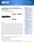
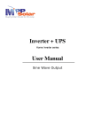
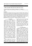
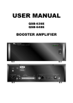
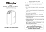
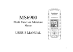
UCG
Powering the World
User Manual
UCG5KVA
Pure Sine Wave Inverter
Brief Introduction
UCG5KVA pure sine wave power inverter is made of high quality power frequency
transformers, advanced CPU control technology, IGBT tubes or FUJI IGBT modules combined
with DSP technology to generate sine wave power source. Inverters with IGBT and DSP
technology are characterized of wide load range, fast response, anti-interference, low self
consumption, high efficiency, etc., They are regarded as the best choice for areas without
grid power or for solar/wind generator systems.
Application Area
Computer systems, communications systems, precision instruments, precision machine
tools, railways, shipping, hospitals, shopping malls, schools, families, travel, alarm system,
widely used for solar and wind power generation equipments. Also, when connected with a
direct external maintenance-free battery bank, it can be used as an EPS (Emergency power
system).
Attention:
1. When utilizing UCG5kva inverter, the switch time between grid power and battery power
is less than 1s, - so it’s not suitable for the loads which requires switch time to be less than
20ms. Per customer’s request UCG3kva inverter can be customized to “0” switch time Please mention the need for this feature when ordering.
2. UCG5KVA inverters can be used within industrial and commercial sectors, it can be
applied to all kinds of loads (normally, the max. starting current of the loads should not
exceed 2.5 times of the inverter rated current.)
2 www.ucgsolar.com
Safety
Please take note of the following safety measures which also applies to inverter loads. Please
read the details carefully and reserve it for future reference.
1. To avoid electric shock, without the guide of a technician do not open the cover of the
inverter or pull the input and output terminals.
2. When functioning the inverter input/output cables should be arranged in proper order to
avoid any cable damage.
3. Inverter power supply lines must be ground connected to avoid electric shock.
4. Do not connect the inverter ground lines to heating pipes, water pipelines, gas pipelines
and other public facilities, - to avoid violating the rights of the third party.
5. Do not connect the ground line and neutral line. If connected together or reversely
connected, it may cause abnormal working of the inverter or lead to electric shock.
6. When the battery voltage is higher than 48V, in order for safety installation and future
easy maintenance, should connect in series with one high current DC switch between
batteries and inverter.
7. For the inverter with AC input(grid charger), please connect in series with one power
switch between grid and inverter to ensure safety.
8. In avoid fire caused by overload, please don’t overload the inverter with appliances.
Corporate - 1.888.417.9312
3
Technology Characters
Main Data (Single Phase)
Model
Specs
Rated power
Input DC
Output current
Instantaneous current
Output frequency
Output AC
Output wave
Output frequency
Voltage stability
AC input(grid)
Overload protection
Under voltage protection
Efficiency
Working Environment
Dimension
Weight
UCG
5KVA
3.2KW
96VDC
13.63A
16.36(10 s)
50HZ
220V
Pure sine wave
50HZ
±5%
220V
3.84KW(120% of the rated power), 10 seconds
84VDC(87.5% of battery rated voltage)
≥80% (full load)
Temperature:0-20~+540
ity: 30~90%
530*315*450mm
42Kg
Relative Humid-
Notice: The UCG3KVA is a off-grid inverter, please do not connect the AC output
to the grid.
Cable Size Option
4 Power
DC Voltage
Wire of DC
AC voltage
Wire of AC
Single phase
5000VA
96V
16mm2
220V
4mm2
www.ucgsolar.com
Attentions
Moving
1. Don’t move the inverter in reverse.
2. Handle the inverter slowly, avoid crash.
3. Before moving, turn off the inverter and remove all wires;
Installation place
1. Put the inverter on a flat ground or spot.
2. Put the inverter in a well ventilated place (at least 50cm surrounding space in one meter
range of the inverter should not have combustible material or heat source).
3. Avoid sun, rain and damp.
4. Put far away from fire.
5. Do not place objects on the inverter.
6. Do not put the inverter in a place with corrosive gas.
7. Best working Temperature: 0~40.
Corporate - 1.888.417.9312
5
Installation Method and Operations
Before wiring, please turn the general switch off (“10” in Diagram 2 - pg. 9).
Wires between the battery and Inverter.
1. According to the input DC voltage(96VDC) requirements of inverter, connect the positive (+, red wire) and negative (-, black wire) of the batteries to relative terminals (positive
connector “8” in Diagram 2 and negative connector “9” in Diagram 2 - pg. 9) of the inverter through one DC switch. Note: Reverse connection is dangerous!
Power input wires (for the models with grid standby function)
1. Grid power cables 220V should be connected to the power inverter via circuit breakers
according to the firewire connector L (“11” in Diagram 2 - pg. 9) and zero line connector N
(“12” in Diagram 2 - pg. 9) connection. Note: The circuit breaker for inverters can not be
used together with any other loads.
Power output wires
1. The power output wires should be connected to the output terminals of inverter according to the firewire connector L (“13” in Diagram 2 - pg. 9) and zero line connector N (“14”
in Diagram 2 - pg. 9) connection.
2. The output wires should avoid any short circuits.
3. The load should be limited to the rated power capacity of the inverter.
ON/OFF
Before turning on the inverter, please re-check all cables and terminals are properly connected, the loads connect should abide to the following rules:
1. Purely resistive loads, the maximum rated power of loads should not be over the inverter
rated power (3.2KW).
2. Purely inductive loads, the maximum rated power of loads should not be over the inverter rated power of 40% (1280W).
3. Resistive and inductive mixed loads, the maximum rated power should not be over the
inverter rated power of 50% (1.6KW).
6 www.ucgsolar.com
Installation Method and Operations
1. Turn on the general switch (“10” in Diagram 2 - pg. 9). The LCD will show “POWER OFF”.
After turning on the general switch the inverter starts initializing the system.
2. Push the start buttons on the front panel after 30s (“2” in Diagram 1 - pg. 8).
3. After 2s, the inverter starts outputting AC power, the LCD show “EMERGENCY POWER”
4. Press the screen page button on the right side of the LCD (“7” in Diagram 1 - pg. 8), the
LCD will show “system OK”
5. Press the screen page button on the right side of the LCD (“7” in Diagram 1 - pg. 8) again,
the LCD will show information of AC input, AC output, loads and battery. When one display cycle finishes, press the screen page button to start next cycle.
6. Turn on the loads.
7. To shut down the inverter, turn off the switches of the loads and then turn off the inverter
general switch (“10” in Diagram 2 - pg. 9).
Notice:
When the inverter shuts off due to the protection features for under voltage, overloads or
over-temperature - Turn off the general switch (“10” in Diagram 2 - pg. 9), ONLY turn it on
after the problem is identified and resolved.
Corporate - 1.888.417.9312
7
Structure and Function Description
Front Panel
Diagram 1 - UCG5KVA single phase 5KVA inverter
1.
2.
3.
4.
5.
6.
7.
8 LED Display: Show for AC-DC voltage and load status;
Start Button: Used to start and shut down the machine
Charging Indicator: Valid when charging function is available;
Battery Charding Indicator: Valid when grid is charging battries;
Inverter Indicator: It is “ON” when Inverter is functioning;
Fault Indicator: It is “ON” when there is a fault also the inverter stops working;
Screen Page Button: To view the data and stop their calls.
www.ucgsolar.com
Structure and Function Description
Back side
Diagram 2 - UCG5KVA single phase 5KVA inverter
8. Positive connector of the battery
9. Negative connector of the battery
10. General switch
11. AC input firewire connector L
12. AC input zero line connector N
13. AC output firewire connector L
14. AC output zero line connector N
15. Vent for cooling fan
Corporate - 1.888.417.9312
9
Structure and Function Description
LCD Display
10 www.ucgsolar.com
Need to Contact Us?
CUSTOMER SERVICE
If you have questions about one or
our products, please call one of our offices
listed below or email us at [email protected]
US Corporate Office
7411 Riggs Road, Suite 208
Adelphi, Maryland 20783
Phone: 1.888.417.9312
Imo State, Nigeria Office
49 MCC Road
Owerri, Imo State
Phone: 083801311
Corporate - 1.888.417.9312
11
UCG Solar Corporate Office
7411 Riggs Road, Suite 208
Adelphi, Maryland 20783
Powering the World.
UCG Solar Locations:
US Corporate Office
7411 Riggs Road, Suite 208
Adelphi, Maryland 20783
Phone: 1.888.417.9312
UCG Solar Major Distributor:
Accra-North, Ghana Office
Accra-North, Ghana
Phone: +233208116862
Lagos, Nigeria Office
Ikota Shopping Complex,
Suite A77
VGC Lekki, Lagos
Phone: 016284773
Imo State, Nigeria Office
49 MCC Road
Owerri, Imo State
Phone: 083801311
www.ucgsolar.com