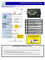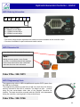
1
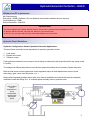
High Country Tek, Inc. Hydraulic Generator Controller – HGC-2 Electronic Controller Solutions for Mobile, Industrial & Marine Applications. Application Guide, Set-up & Information Manual. Manual Part No. 021-00160 May 2009 Hydraulic Generator Controller – HGC-2 Important Notes: This product has been designed to interface directly with any manufacturers range of proportional pressure and/or flow control valves, variable pumps, motors and manifold blocks currently available. Please contact the factory by the e-mail address given below or nearest High Country Tek, Inc. distributor for further technical information and availability. Application Limitations: High Country Tek, Inc. (HCT) designs and supplies products specifically for use in commercial, industrial and mobile control applications with products only warranted for this type of use. HCT distributors are not authorized to approve the use of any HCT product in any of the following applications: • Any product that comes under the Federal Highway Safety Act, i.e., steering/braking systems for passenger carrying vehicles or on-highway • Aircraft ( private, military, commercial or other ) or space vehicles. • Ordnance equipment ( fixed or mobile ). • Any end product that, when sold, comes under the U.S. Nuclear Regulatory Commission rules and regulations. Specific written approval for any application of HCT products in any of the above named applications should be obtained from High Country Tek, Inc and consultation with our factory engineers is advised in unusual situations where applicability is questionable. System Part Numbers: • Controller Module :-………………………………………….………… See rear of manual for ordering info. • Controller Graphical User Interface ( GUI ):-………………………. P/No: 023-00228 • HGC2 controller software CD:-………………….……….………...... Contact HCT customer service for info • Controller info manual:-……………………………………………….. P/No: 021-00160 • Programming Cable:-…………….……………………………………. P/No: 999-10166 • HGC-2, 8-pin Connector Kit:-…………..……..………………………. P/No: 999-10073 IMPORTANT NOTE:High Country Tek, Inc. reserves the right to upgrade, revise or better any controller as technology improves without notice being given. Wherever possible, full downwards compatibility for both hardware and software on replaced controllers will be maintained but it is the users responsibility to ensure that the latest technical details or literature is being used for application reference. If you are unsure of the literature, hardware or software revisions you have, or suspect that it is an older revision, please send an e-mail request for the latest releases to [email protected] ALL information contained herein is copyrighted to High Country Tek, Inc - © 2009. 2 Hydraulic Generator Controller – HGC-2 Important Notes: ALWAYS - Take a few minutes to FULLY read THESE information / data sheets BEFORE starting. ALWAYS - Keep High Voltage AC cables separate from Low Voltage DC signal and supply cables. ALWAYS - Make sure the unit supply voltage is the same as the coils on the valve being driven ! ALWAYS - Ensure that you are aware of the available adjustments and consequences on the electronics and hydraulics. ALWAYS - Make sure you have the correct tools to do the intended job ( i.e. P.C., software ) e.t.c. ALWAYS – ‘Isolate’ this unit from all other equipment BEFORE any form of welding takes place. ALWAYS - Check ALL connections to and from this unit to ensure NO short or OPEN circuits. ALWAYS - Check the units supply voltage is CORRECT, ‘ ELECTRICALLY CLEAN ’ and STABLE. ALWAYS - Operate the units within specified operating temperature for best & reliable performance. ALWAYS - Ensure that any unused wires / terminals are terminated safely and not shorted together. ALWAYS - Isolate the controller if ANY form of battery charging or battery boosting takes place on the vehicle. ALWAYS - Ensure ALL valve connectors are wired correctly, secure, locked and connected to correct coils. ALWAYS - Observe the set-up procedures in this manual for best operational results. ALWAYS - Follow and abide by local and country health and safety standards – protect yourself and others ! NEVER - Arc Weld or Charge Batteries with this driver unit connected as damage can occur. NEVER - Attempt to use this unit if you are unsure of electrical OR hydraulic connections or expected operation. NEVER - Attempt to use this unit in Areas where other AC or DC coils HAVE NOT been fully suppressed. NEVER - Use a power supply that is not rated for the correct required O/P current under full load. NEVER - Allow wires TO or FROM the unit to short circuit ( to each other or chassis/cabinet e.t.c. ). NEVER - Attempt to use this unit in areas of intense RF without adequate screening measures. NEVER - Disconnect or connect wires to or from this unit unless it isolated from the power supply. NEVER - Use this unit in temperatures that exceed those specified as operation may be effected. NEVER - Start this unit without ensuring ALL work areas are clear of personnel ! Hydraulic generators can produce LETHAL voltages when operating. Remember to abide by all health and Safety rules and keep yourself and work colleagues safe ! The information in this guide is the intellectual property of High Country Tek, Inc. and should be considered at all times as strictly company confidential. It shall not be copied or transmitted by any format to any third parties without our knowledge and express written permission. 3 Hydraulic Generator Controller – HGC-2 Product Features: Digital controller for repeatability, reliability and accuracy in your application Accuracy is dependent on HGC-2 module ‘Tuning’ and the type of hydraulic circuit used 100 to 250VRMS generator output compatible 50 or 60 Hz settable for global sales opportunities User configurable Under and Over frequency handling. Wide supply voltage 9 to 28VDC and full reverse polarity protection. -20ºC ( -4ºF ) to +80ºC ( +176ºF ) controller operational temperature range. Valve dither selectable in steps up to 1000Hz Fully adjustable PID closed loop control for smooth speed control with fast correction and accuracy Designed to meet CE criteria to latest standards. Diagnostic ‘Status’ LED shows I/O status and module operation at a glance. ‘Blinking’ error code LED for fast on-site system wiring / coil fault detection Solenoid PWM current output is short circuit protected. IP67 ( NEMA 6 ) rating on module for harsh environment reliability ( connector IP rating may differ ). Single Deutsch 8 way male connector for easy system wiring. Separate Infra-red communications connector for programming, monitoring and diagnostics. Rugged encapsulated enclosure withstands harsh environments found in mobile applications. Field programmable and upgradeable for future complex fan system applications. Intuitive Graphical User Interface ( GUI ), easy and fast to use for set-up and diagnostics Runs on any PC with Windows® XP Professional or Vista Business and Ultimate software. Completely user configurable for setting confidentiality. Compatible with ALL major hydraulic manufacturers suitable hydraulic products. Manual Variations Note: PC Screen shots shown in this manual may have small differences to the picture being displayed on the Graphical User Interface you are using, This is normal and is due to the PC software being updated as we add more functionality. High Country Tek, Inc. reserve the right to improve this product at any time and without notice. This manual may contain mistakes and printing errors. The information in this publication is regularly checked and corrections made in the next issue. Please check our website or contact our customer support for latest version. HCT accepts NO liability for technical mistakes or printing errors, or their consequences. 4 Hydraulic Generator Controller – HGC-2 Software and PC requirements Min Requirements, Disk space: 165MB (Software, GUI and National Instruments embedded drivers required). Physical Memory: 2.5MB Screen Resolution: 1024X768 Important Note: • The unit is supplied with 3 default .dat files for the 3 current HGC-2 module versions available from HCT. • If ‘ON-line’ with the controller, only open the .dat file for your current model. • If ‘OFF-line’ you can open and save your customized settings to any of the three. Hydraulic Circuit Guidelines: Hydraulic Configurations Used in Hydraulic Generator Applications: There are three commonly known approaches to hydraulic generator circuits: 1. Load sense. 2. Bypass flow control. 3. Pressure control. Field experience shows the most common circuit design is load sense (with proportional two way acting as the LS orifice). This design has difficulty with piston motors and the spikes induced by the low number of power elements. Both the load sense and the bypass flow control approach require a fixed displacement motor of some technology ( gear, vane, bent axis piston e.t.c. ). Motors with integrated cartridge valves make for a cleaner installation and reduce the need for leak paths, manifolds, hoses and fittings e.t.c. in confined spaces normally seen in generator sets. Orifice added here is dependent on pump compensator requirements and system design 5 Hydraulic Generator Controller – HGC-2 About the HGC-2 Controller: The HGC-2 Hydraulic Generator Controller is the latest addition to the HCT family of rugged controller modules, designed for reliability under extreme conditions. The highly cost effective HGC-2 is designed to control a generator driven by a hydraulic motor where speed is controlled by a proportional solenoid valve, either directly at the motor or as part of the pump compensator. The HGC-2 is a closed loop controller that monitors the AC line voltage from the generator output for outer loop closure and provides the necessary current to a valve coil in order to maintain the desired generator frequency. A single LED indicator on the top of the unit to provide an overview of the operating status The unit has enough processing power and functionality when operating as a single control module to support a wide range of hydraulic generator applications. As with all of the HCT modules, the HGC-2 is packaged in a small rugged enclosure. All connectors are sealed and the module is encapsulated to withstand extreme conditions in the harsh mobile operating environment. The HGC-2 is designed to make the generator unit easy to configure and control. The hardware contains the framework software where the parameters can be changed depending on the users needs via the PC Graphical User Interface (GUI). The GUI has been organized into various user screens that are logical and easy to understand. Terminology has been used that is commonplace through the industry to allow easy configuration and is intended to cater for a wide range of users with varying levels of computer familiarity. Once configured, all the settings are stored in permanent memory within the unit, even when no power is applied. The HGC-2 is housed in a small, rugged housing and is fully encapsulated for maximum reliability. All I/O connections are made through a heavy duty industry standard 8-pin male Deutsch connector. PC Graphical User Interface (GUI): HGC-2 set-up, monitoring, health checks and diagnostics can be accessed through the supplied GUI. This program will operate on PC using a based Windows® XP Professional or Vista Business and Ultimate operating system and is password protected to maintain module parameter integrity by only allowing authorized users to access different levels of the controller settings. Passwords protect the settings of the module at all times and are needed to make any changes to the operational parameters. The interface is designed to be simple to use and follows the familiar Windows® menu format with drop down option screens to select the various options available at the user level allowed. Explanation of the screens are covered in detail, later in this guide. Once the PC has been connected to a ‘live’ HGC-2, and the GUI program started, a free communications port will be either automatically allocated (Windows® XP Professional or Vista Business and Ultimate ) or will have to be manually chosen from a menu that will be displayed. After communications have been established, the user will be presented with the initial information screen that will give all the basic information needed to assess the health of the system. Real time graphing is available here to monitor a wide range of items ( selectable from a drop down and select list ) and for remote diagnostics, a ‘Data Log’ button will start a Windows Excel file that can be used as a monitor for comparison to other logged charts during the system’s life or can be E-mailed to an engineering source if there is a problem for diagnosis. 6 Hydraulic Generator Controller – HGC-2 Loading the HGC-2 GUI onto your PC: Go to www.highcountrytek.com or contact HCT to ensure you have the latest revision of the HGC-2 GUI The PC Graphical User Interface ( GUI ) is a self extracting and installing program that will reside on the chosen host PC hard drive. It is recommended that the user allow the defaults to be used for easy future update installation, but the option is given to allow the user to choose where the program should be located. It is NOT recommended that this program be run from a network as it needs access to certain files available only in the Windows directories. To start the installation process, insert the CD ROM or if this does not work, search for the ( contact Factory for latest *.exe program ) file on the cd and ‘run’. Graphical User Interface (GUI) Overview: HGC-2 ‘Dashboard’ view: Once the PC is connected to the HGC-2 module and the Graphical User Interface (GUI) started, communications will be established and this ‘Dashboard’ screen will appear. From here the user can observe all operations of the controller as well as see the settings for individual characteristics that have been programmed. If the user is authorized and has the correct password(s), the unit settings and other information can also be configured from here. OFF-LINE: The Graphical User Interface (GUI) screens are designed to help the user understand the operation of the HGC-2 as well as allow set-up and diagnostics when needed. When the PC is connected to the controller, and the GUI is started, there may be several seconds while the PC establishes communications with the module. During this time, the ‘OFF LINE’ indicator will be present. This indicator also displays if communications are lost or dropped during connection between the PC and the module. Under normal circumstances, reconnection of communication will be automatic. If the module fails to re-connect, the user may have to cycle power to the HGC-2 to perform a hard reset. 7 Hydraulic Generator Controller – HGC-2 Explanation of major windows: 1 1. The header of the GUI window tells the user the version of the software and which controller should be connected to the host PC. 2. This main indicator should be bright GREEN to show a correct operational function of the controller, with the light showing real-time status of the units operation. If there is an error of any type, this indicator will be bright RED with the fault description shown under the light until the fault is cleared. 3. This digital display shows in real-time the DC supply voltage to the HGC-2 controller. 2 4 3 8 5 7 6 9 4. This meter shows the user the actual feedback frequency that is being measured from the generator under control. The needle should be in the ‘GREEN’ band for correct operation. 5. This bar-graph and digital meter shows the user the PWM DC current trend and value that is being supplied to the control valve used to regulate the generator rotational speed. This valve may be direct on the motor or as part of a compensator assembly on a variable displacement pump. 6. This graph area allows the user to watch operation of various signals to observe stability and speed of correction e.t.c. as required. 7. This table shows at a glance, all of the settable parameters that may be adjusted to suit the individual generator set needs. If the table window has a blue background with yellow text, he user may enter a value directly and use the up/down arrows to adjust the value as required. 8. The changes made to the parameters in the table mentioned in 7. only take effect within the controller when this ‘Send Changes’ button is clicked. 9. This button allows the user to ‘LOG’ controller functionality directly to the connected PC hard drive. The data is saved in CSV format ( Excel compatible ) for easy and quick graphing of operation. NOTE: With NO password entered, the options bar will only show ‘Help’ and ‘Quit’ highlighted as these are the only choices available to the un-authorized user. 8 Hydraulic Generator Controller – HGC-2 ‘Help’ Menu Options: The ‘Help’ menus has two drop down options: 1. Print Parameters 2. View Help. 3. About Controller. ‘Print Parameters’ when clicked, this option will allow the user to get a hard copy of the controller settings via the default printer connected to the PC ‘View Help’ when clicked, will open a PDF format file that is the complete manual for the HGC-2 controller, allowing local on-site information support for the user. ‘About Controller ’ when clicked, will open another window that will show the user relative information on the controller model, Firmware, GUI and communications versions as well as contact information and web address for support. Click ‘OK’ to exit the window. ’QUIT’ Menu Options: The ‘Quit’ menus has two drop down options: 1. Quit. ‘Quit ’ when clicked, close the Graphical User Interface (GUI) correctly and release any USB communications ports that may have been used for set-up, allowing other programs to use these resources. NOTE: It is important to note that if the quit is clicked before the ‘Send Changes’ button, the GUI will close and the controller will default to the settings stored in the internal memory with no user changes taking place. 9 Hydraulic Generator Controller – HGC-2 Controller Setting Security - Passwords: Password Protection: The password is entered after first clicking the ‘HCT’ logo in the top left of the ‘dashboard’ screen, This opens another window where the password is entered. NO Password – User Level: This level allows the user to only observe operation but not make any changes to the parameter settings or operation of the controller. OEM level: This level allows the equipment OEM access to all settings and controller functions. NOTE: Passwords may be obtained by contacting High Country Tek, Inc, sales and support department ‘File’ Menu Options: The ‘File’ menus has two drop down options: 1. Read File. 2. Save File. ‘Read File’ when clicked, will allow the user to look for previously saved HGC-2 setting profiles and up-load these into the PC and then into any HGC-2 controller. IMPORTANT NOTE: When editing the default data file that comes with the controller, ensure that you choose the correct file name for the model of HGC-2 ordered and used. For example: Use data file name "HGC-2-12.dat“ for the "HGC-2-12“ ‘Save File ’ when clicked, Allow the user to save to PC hard drive the setting file for an HGC-2 controller. This feature is used to store different generator model profiles that can be retrieved quickly at any time as required 10 Hydraulic Generator Controller – HGC-2 ‘Unit’ Menu Options: The ‘Unit’ menus has three drop down options: 1. Read Parameters. 2. Send parameters. 3. Find Controller. ‘Read Parameters’ Selecting this option allows the GUI to read the parameter setting file from a connected controller to allow backup, editing or copying to other controllers. ‘Send Parameters ’ This option sends all the parameters currently shown on the screen down to the controllers permanent memory to become the settings used from this point forward. ‘Find Controller ’ This option will actively search communications ports for a genuine HGC controller and then refresh the parameter screen with the settings in that found module 60 or 50Hz Screen Differences: The HGC-2 controller is designed to cater for global markets and as such, can manage both 110VAC and 240VAC generator outputs at either 50 or 60Hz. The line ( high voltage ) feedback is taken directly from the generator secondary with NO other external equipment or components needed. The easy to use Graphical User Interface (GUI) allows the user to select feedback voltage as well as frequency with the GUI meters and displays changing to ensure that the user is always presented with the best resolution graphics that will allow 11 Hydraulic Generator Controller – HGC-2 ‘Data Logging’ Options: The HGC-2 controller can log operational data as long as it is connected to the host PC. The data is directly saved onto the PC hard drive as a CSV format file, into a location that can be selected by the user. Logging is started by the user clicking the ‘Log Data’ button The controller logs the following data: 1. Valve coil Current 2. PSU voltage 3. Frequency feedback Information transfer rate from the controller to the CSV file is governed by the host PC performance Fault Screens: OPEN CIRCUIT FAULT DETECTED: This fault is displayed when the controller detects that the proportional coil being driven by the PWM output has become dis-connected or has failed internally to an open-circuit condition. Other causes of this fault detection may be broken wires within the generator set enclosure. If this fault is triggered, the HGC-2 PWM output will be set to zero output ( i.e. minimum generator speed ) until the HGC-2 is first disabled and reenabled or the supply power to the unit is cycled and no further open circuit is detected. To correct this issue, the operator should first isolate and fully stop the generator and check all connections to and from the HGC-2 controller for correct and firm connection. If the faulty still exists, check the solenoid coil for continuity and correct Ohmic value ( see manufacturer details ) or change the solenoid coil. 12 Hydraulic Generator Controller – HGC-2 ‘Fault’ Screens: FREQ. FAULT DETECTED: This fault is displayed when the controller detects the high voltage feedback frequency is either below or above the Min and Max frequency settings selected. The fault indicator only appears after a time period to allow for minor fluctuations in frequency that may occur during ‘load-no-load-load’ transitions If this fault is triggered, the HGC-2 PWM output will be set to zero output ( i.e. minimum generator speed ) until the HGC-2 is first disabled and reenabled or the supply power to the unit is cycled. To correct this issue, the operator should first isolate and fully stop the generator and check the high voltage feedback connections to and the HGC-2 controller for correct and firm connection. If these are secure, the settings for the HGC-2 may need to be adjusted – please contact HCT for assistance. GROUND FAULT DETECTED: This fault is displayed when the controller detects the there is a physical or short circuit connection between the solenoid +output and any GROUND point on the generator set. This could be caused by a frayed wire touching the inside of the enclosure as an example. To correct this issue, the operator should first isolate and fully stop the generator and check the connections to from the HGC-2 controller to the solenoid for correct and firm connection. If these are secure, the user should inspect all the cables connected to the HGC-2 for wear and possible touching to a ground point. Once this fault is triggered, the HGC-2 PWM output will be set to zero output ( i.e. minimum generator speed ) until the HGC-2 is first disabled and re-enabled or the supply power to the unit is cycled. 13 Hydraulic Generator Controller – HGC-2 Connecting the HGC-2 to the Programming Cable: In order for the HGC-2 to communicate with the PC User Interface, a programming cable ( 999-10166) must be temporarily connected to the PC USB port and also to the HGC-2 controller. The controller and programming cable use Infra-red transmission technology for fast data transfer and the user must ensure that the programming head is correctly aligned and fitted to the controller for successful communications. Philips Pan head screw Philips Pan head screw Connector profile Ensure this profile meets connector profile Grip top and bottom here to slide programming head into position 1. Install the HGC-2 Graphical user Interface onto the PC that will be used for set-up and configuration of the HGC-2 2. Ensure you have, if necessary, installed the USB drivers needed for the programming cable onto your PC that will be used for setting-up the HGC-2 ( found ob software CD or at www.highcountrytek.com 3. Wipe clean both the surface of the HGC-2 module, directly under the connector and also the underside of the ‘Programming head’, making sure there is no debris or material that could cause an issue. 4. Hold the ‘Programming head’ such that the label is facing upwards as shown in the picture to the right. 5. Holding the ‘ Programming head’ firmly, top and bottom between thumb and forefinger, slide it UNDER the two Philips Pan head screws ( see bubbles above ) until the profile in the ‘Programming head’ meets and matches the connector profile. Only now is the head aligned correctly with the optical coupling. 14 Hydraulic Generator Controller – HGC-2 HGC-2 Controller Settings and Descriptions: TARGET FREQUENCY - The Target Frequency parameter sets the desired output frequency of the generator to 50Hz or 60Hz. The Proportional parameter is a variable type. PROPORTIONAL GAIN. - The Proportional parameter sets the proportional gain in the control loop. The proportional gain represents the P term in a PID control loop. The proportional term is simply a multiplication of the error which is added to the output. The Proportional parameter is a variable type. INTEGRAL GAIN – Integral Gain is used to determine the integral or I term in the PID control loop. The integral term is a accumulation of error over a period of time. The integral term is generally used to overcome an offset in the output or to correct for very small deviations over time at a fixed command. The Integral Gain parameter is a variable type. DERIVATIVE - The Derivative parameter sets the derivative gain in the control loop. The derivative gain represents the D term in a PID control loop. The derivative term is the rate of change of the error. The derivative term is generally used to increase the responsiveness of a system. The Derivative parameter is a variable type. PID LOOP TIME – PID Loop Time represents the PID loop closure time in number of dither cycles. Therefore, the lower the number, the more quickly the system will respond to error. The PID Loop Time parameter is a variable type. RAMP UP RATE – The Ramp Up Rate sets the rate at which the controller will increase current to the solenoid once enabled. Once the AC frequency is within approximately 10% of the target frequency the closed loop control algorithm will take over. The Ramp Up Rate parameter is a variable type. RAMP DOWN RATE – The Ramp Down Rate sets the rate at which the controller will decrease current to the solenoid after the enable signal is removed. Once the AC frequency is within approximately 10% of the target frequency the closed loop control algorithm will take over. The Ramp Up Rate parameter is a variable type. DITHER FREQ. - The Dither Frequency parameter has 11 options for dither control. The choices are 50, 75, 100, 125, 150, 175, 200, 225, 250, 275, 300, 350, 400, 500 and 1000 Hz. Dither control provides low frequency modulation which is required in many proportional valve applications. The Dither Frequency parameter is variable. MINIMUM OUTPUT - The Minimum Output parameter represents the minimum current of the output. This is often referred to as the dead band. The value displayed represents the current in milliamps (amps for -12A, 25A). The Minimum Output parameter is variable. 15 Hydraulic Generator Controller – HGC-2 HGC-2 Controller Settings and Descriptions: MAXIMUM OUTPUT - The Maximum Output parameter represents the maximum current of the output. This is often referred to as the gain. The value displayed represents the current in milliamps (amps for -12A, -25A). The Maximum Output parameter is variable. MINIMUM FREQ - The Minimum Frequency parameter is used to establish the minimum frequency for the desired range of operation. A frequency below this value will be handled according to the Below Min Freq parameter. The Minimum Frequency parameter is a combination variable/monitor type. BELOW MIN FREQ – Below Minimum Frequency selects which function to use when the frequency falls below the Minimum Frequency. NO FAULT will ignore the condition and TIMED FAULT will trigger the corresponding fault causing the controller to shut down after the set time. The Below Minimum Frequency parameter is variable. MAXIMUM FREQ - The Maximum Frequency parameter is used to establish the maximum frequency for the desired range of operation. A frequency above this value will be handled according to the Above Max Freq parameter. The Maximum Frequency parameter is a combination variable/ monitor type. ABOVE MAX FREQ – Above Maximum Frequency selects which function to use when the frequency rises above the Maximum Frequency. NO FAULT will ignore the condition and TIMED FAULT will trigger the corresponding fault causing the controller to shut down after the set time. The Above Maximum Frequency parameter is variable. FAULT TIME – Fault Time sets the amount of time that a frequency fault condition exists before the controller shuts down and indicates the fault. The Fault Time parameter is variable. CC MODE CURRENT – The CC Mode Current sets the desired output current used when the constant current mode is enabled. The CC Mode Current parameter is variable. AC FREQUENCY – AC Frequency displays the nominal frequency of the Feedback Input. The Feedback parameter is a monitor type. OUTPUT CURRENT - Output Current displays the nominal current being supplied to the output. The Output Current parameter is a monitor type. SUPPLY VOLTAGE - The Supply Voltage parameter displays the module’s power supply voltage. This value is included as an aid to troubleshooting. The Supply Voltage parameter is a monitor type. 16 Hydraulic Generator Controller – HGC-2 Initial Set-up Procedure: The following steps are recommended when commissioning a HGC-2 controller: 1. Select the desired operating frequency. 2. Set the Minimum and Maximum Outputs according to the valve data sheet. 3. Set the Dither Frequency as recommended by the valve manufacturer. ( NOTE: Higher dither frequencies can sometimes be used in closed loop systems to improve frequency response). 4. Set the Ramp Up Rate and Ramp Down Rate as desired. 5. Adjust the PID parameters as needed to optimize the system response: Start with Proportional (P) setting and increase to achieve a stable system. Once stability is achieved, gradually increase the add Integral (I) setting and finally, Increase the Derivative (D) setting as needed to improve system response and/or stability. Troubleshooting - Constant Current Mode: The Constant Current Mode, or CC Mode, is useful for setup and troubleshooting. It can also be used in electrically noisy environments where the AC feedback might become overly distorted. In this mode the controller will maintain a constant output current to the valve coil without regard to the AC line feedback. To initiate CC Mode, apply a signal to both the CC Mode Enable and the main Enable simultaneously. Once started, the CC Mode Enable signal can be removed and the controller will continue in this mode until the main Enable is removed. CC Mode cannot be initiated after the controller is started in normal mode. 17 Hydraulic Generator Controller – HGC-2 Operational Guide: The following section gives the user a generic overview of expected control results once the controllers PID settings have been optimized for the individual generator set-up being produced. These results are for reference only and may vary depending on individual circumstances, product technologies Hydraulic Circuit configuration: • Prime Mover – 50KW @ 1800 RPM on Variable Frequency Drive • Pump – 45 cc/rev load-sense pump • Valve - 2 position, 2 way, non compensated proportional size 12 cartridge with 12 VDC coil • Oil temperature – forced air cooled with ambient air • Oil type – Standard Hydraulic Mineral oil Generator Configuration: • Armature – Mec Alte' 2 pole, S16F-180/B rated at 8KW @ 3600 RPM (de-rated to 6KW for severe duty service) • Hydraulic Motor – Sauer Danfoss SNM2-FL/08-SSC06-RZZ1 • Voltage regulator – dual capacitor, passive Electrical specification: • Regulated power supply 13 VDC ( from integrated PSU on test application ). • HV electrical loading by combined resistive and inductive loads Test Specifications – Stability With Load Changes No load – Full load – No load test 75 Frequency - Hz 70 This result shows what can be achieved with the correct settings on the controller. The graph left demonstrates the recovery time of the output frequency when the generators load is fully applied, then fully removed, then fully applied once more. This sequence of instantaneous events is probably the worst that the generator will see, yet undershoot, overshoot and steady state are well controlled and acceptable for the majority of today's applications. 65 60 55 50 45 40 1 16 31 46 61 76 91 106 121 136 151 166 181 Time base = Milliseconds 18 Hydraulic Generator Controller – HGC-2 Operational Guide – DC Supply Voltage Fluctuation: DC Supply Voltage Fluctuation 13V – 10V – 13V within 1 second 80 Frequency - Hz 75 The HGC-2 has been designed to work under extreme conditions seen in mobile equipment. One variable that can effect operation is the vehicle battery voltage, but as can be seen in the graph, right, the fluctuations that can occur have very little effect on the controlled frequency of the generator output, with good control being shown at all times. 70 65 60 55 50 45 40 1 3 5 7 9 11 13 15 17 19 21 23 25 27 Time base = Milliseconds Test Specifications – Prime Mover Speed Change Prime Mover Speed changes 80 Frequency - Hz 75 In the event that the prime mover has variations in speed ( i.e. engine momentary loading ), the controller must be able to react quickly and smoothly, avoiding major over and undershoots and recovering to steady state as soon as possible. This test demonstrates the generator output with prime mover speed changes from mid range ( normal = 3600RPM ) to minimum ( 3400 RPM ) and then to maximum ( 3800 RPM ). 70 65 60 55 50 45 40 1 16 31 46 61 76 91 106 121 136 151 166 181 Time base = Milliseconds Test Specifications - General: There are few hydraulic generator specifications existence. The most common is the NFPA specification for generators applied to fire protection equipment. It is based on a non-electronically controlled hydraulic generator (load sense pump with fixed orifice) and thus addresses dynamics specific to that design, such as frequency droop over time under full load (to assess volumetric efficiency losses). This specification is attached. A generator using either test specimen will meet this specification. 19 Hydraulic Generator Controller – HGC-2 HGC-2 Electrical Specification: 1. Housing Type:- HCT unique ‘encapsulated’ block. 2. Input Supply Voltage: +9 to +28VDC ( Absolute Maximum ) 3. Input Supply Current: Valve Current Setting + 50mA Quiescent (Max) 4. **Feedback Voltage:- 100 to 250VRMS ( See note below in yellow box ) 5. O/P Current Ranges:- 600mA, 1.2A or 2.5A ( specified at time of order ) 6. Solenoid Min Ohms:- 2Ω minimum resistance 7. Dither Frequency : Software adjustable, ~50Hz to ~1KHz 8. Housing Material:- ABS, black 9. Encapsulation:- Flameproof epoxy resin 10. I/O Connections:- 8 pin Deutsch - DTS06 - Male 11. Mounting:- 2 x No. 6 ( 4mm ) screws . 12. Working Temp.:- -20ºC (-4ºF) to +80ºC (+176ºF) ( operational ) 13. Storage Temp.:- -40 (-40ºF) to +85 ºC (+185ºF) 14. Humidity:- 95 to 100% NON condensing 15. NEMA/IP Rating: NEMA 6 / 67 ( module only ) 16. Operating System: Windows® XP Professional / Vista Business and Ultimate Compatible 17. Unit Settings: All by PC user interface 18. User PC interface P/No:- 023-00228 19. USB Communications: Optical link - Infra-red 20. Interface Cable P/No:- 999-10166 HGC-2 Module overview: 1. Main Input /Output connector for HGC-2 1 2. STATUS led with blink code for local diagnostics 2 3. Infra-red transmitter lens ( flush with module ) 4. Infra-red receiver lens ( flush with module ) 3 4 20 Hydraulic Generator Controller – HGC-2 HGC-2 Error code Description (STATUS): Blink OFF Definition System is OK and operating normally 2 Open Circuit On Controller Output – wires to solenoid disconnected while under power 3 Short Circuit On Controller Output - wires or solenoid have become short circuited 4 Ground Fault – a short circuit has occurred between the solenoid + output and ground 5 Frequency Fault – output frequency has been below min. or above max. for greater than fault time Note:• The ‘STATUS’ led is a monitor is used to indicate locally the controller operation only • NO external output is provided to mimic the STATUS led HGC-2 Hardware Description: A B C 1 2 3 4 8 7 6 5 C E STATUS Hydraulic Generator Controller HGC-2 D Label Inches Millimeters A 3.0 76.2 B 2.0 50.8 C 0.25 6.4 D 1.0 25.4 E 0.188 4.80 www.highcountrytek.com IMPORTANT NOTES:• ALWAYS Mount HGC-2 controller with I/O connector facing downwards to avoid debris collection. • Recommended tightening torques for securing bolts on the HGC-2 module are as follows:For 2 x #6 (4mm) bolts - Dry Torque = 6 Ft-Lbs - Lubricated Torque = 4 Ft-Lbs 21 Hydraulic Generator Controller – HGC-2 Electrical System Connections: Pin Function 1 +VDC Input Supply 2 0VDC Input Supply 3 +Solenoid Connection O/P 4 -Solenoid Connection O/P 5 AC feedback Neutral I/P 6 AC feedback Line I/P 7 Constant Current Mode enable I/P 8 Controller ENABLE I/P Beware of HIGH VOLTAGE when operating any generator system – high voltage can be LETHAL – observe ALL laws, by-laws and health & Safety recommendations for your immediate location, state and/or country. HGC-2 Module Connection notes:- 1. Ensure that the recommended fuses ( FS1 & FS2 ) is installed in the system for full protection and warranty. 2. Use separate cables for each connection as shown above. 3. Connect proportional valve coil cables and run separate from all/any high voltage wires. 4. Ensure that high voltage feedback cable is protected to prevent insulation wear during usage through vibration 22 Hydraulic Generator Controller – HGC-2 HGC-2 Ordering Information: H G C 2 - 1 2 Output Current Range: 06 - 600mA current range 12 - 1200mA current range 25 - 2500mA current range Notes: •The current range chosen represents the maximum current available at the controller output. • See rear of controller for part number and model number HGC-2 Connector Kit: 8 way Metri-Pack 150 series MALE connector Note:Mating connector gender:- 8 way Female ( Socket ) kit complete with pins and separator. Correct crimp tool must be used, contact HCT sales and service for more information Order P/No.: 999-10073 HGC-2 Programming Cable: The programming cable is USB compatible and requires 5VDC power from the USB port to operate. The programming method is infra-red and will only work when the head is securely mounted to the HGC-2 controller. The head is a tight ‘push-fit’ using the two screw-heads either side of the Deutsch connector for location. The head should be mounted with the ‘BLACK’ side downwards facing the controller, ensuring that it is fully pushed home. Order P/No.: 999-10166 23 Hydraulic Generator Controller – HGC-2 Mining & Exploration High Country Tek, Inc has been working with the fluid power industry for many years, solving the tough problems and producing unique and mechanically robust products that continue to work reliably in the most extreme and hostile environments that we see hydraulics being applied in today. Agriculture Cranes & lifts Refuse & Re-cycling Construction Off-Road vehicles Forestry, Wood & Pulp Reclamation & Salvage Oil Field & Sands Our controllers are ALL manufactured and tested in the U.S.A. and can be sent anywhere in the world. Demolition Equipment Cooling Solutions Military Apparatus Please contact us to discuss your next project, product training or system application; we would be pleased to work with you and your team. Specialty Use Remote Control Power Generation Emission Controls Integrated Drivers Valve & Pump Controls Contact Us: For product orders, delivery, pricing, training or any other customer service related item, please contact us through E-mail at [email protected] www.highcountrytek.com High Country Tek, Inc. reserve the right to improve this product at any time and without notice. This manual may contain mistakes and printing errors. The information in this publication is regularly checked and corrections made in the next issue. Please check our website or contact our customer support for latest version. HCT accepts NO liability for technical mistakes or printing errors, or their consequences. Manual Part No. 021-00160 HGC2-Man-D.ppt High Country Tek, Inc. 208 Gold Flat Court Nevada City, CA, 95959 Tel: (1) 530 265 3236 Fax:(1) 530 265 3275 24 Copyright © High Country Tek, Inc. - 2009