1
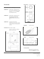
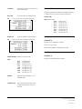
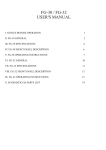
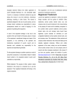
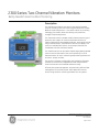
2300 Series Two Channel Vibration Monitors Bently Nevada* Asset Condition Monitoring Description The 2300 Monitors feature two seismic channels and a speed channel, providing continuous monitoring and protection for BOP (Balance of plant) equipment. It is a perfect match for proactively managing your assets, rather than waiting until production outages to replace equipment. The 2300 series monitors enable condition based monitoring and protection with support for various interfaces and functions. Inputs include seismic and speed transducers, and outputs include relays, buffered output, TCP/IP Ethernet, and an LCD display. This monitor is available with either 4-20 mA output (2300/20) or a TrendMaster SPA line interface (2300/25). The 2300/20 Monitor can be used to replace legacy Bently Nevada monitors such as the 1900/27, but more importantly it is a full featured monitor for use in monitoring and protecting assets such as motors, pumps, and fans. The monitor is software configurable, and includes configuration software. There is also an integrated LCD and multiple LEDs to show the channels’ real-time data and status locally. Effective plant asset management, and particularly effective fleet management of machinery assets, often depends on remote access using condition monitoring software such as System 1. Specifications and Ordering Information Part Number 105M0340-01 Rev. A (01/15) Page 1 of 10 Monitor Key Features 2300/20 2300/25 Two – 4-20mA outputs Trendmaster SPA interface Two relay outputs with programmable setpoints Two relay outputs with programmable setpoints Ethernet 10/100 Base-T communication for configuration using Bently Nevada Monitor Configuration software (included) Ethernet 10/100 Base-T communication for configuration using Bently Nevada Monitor Configuration software (included) One dedicated speed and Keyphasor channel supporting Proximity probes, Magnetic pickup and Proximity switch type sensors One dedicated speed and Keyphasor channel supporting Proximity probes, Magnetic pickup and Proximity switch type sensors Three buffered transducer outputs (including keyphasor signal) providing short circuit and EMI protection. Buffered outputs for each signal are through BNC connectors. Three buffered transducer outputs (including keyphasor signal) providing short circuit and EMI protection. Buffered outputs for each signal are through BNC connectors. Continuous monitoring and protection Continuous monitoring and protection LCD display showing vibration amplitude, setpoints, and speed. LCD display showing vibration amplitude, setpoints, and speed. Two acceleration inputs with synchronized sampling for advanced diagnostics. Two acceleration inputs with synchronized sampling for advanced diagnostics. Key measurements(Direct 0-pk, pk-pk, True RMS, Derived pk, integrated direct pk, Speed) real-time provided with alarm configuration Key measurements(Direct 0-pk, pk-pk, True RMS, Derived pk, integrated direct pk, Speed) real-time provided with alarm configuration LEDs show the monitor status LEDs show the monitor status Local contacts for positive engagement of channel bypass, configuration lockout, and reset Local contacts for positive engagement of channel bypass, configuration lockout, and reset Optional Modbus over Ethernet Optional Modbus over Ethernet Recommend for Demonstration Kit 2300/20_KIT-003 1 - 2300/20 Monitor 1 - 6 ft shielded Ethernet cable 2 - Accelerometer sensors 2 - 4.8M accelerometer cables To be ordered separately 106M7607-01 Power supply: 110/220 VAC to 24 VDC DIN mount (30W power supply package, -25°C ~70°C) Specifications and Ordering Information Part Number 105M0340-01 Rev. A (01/15) Page 2 of 10 Specifications Inputs / Outputs o Supply Voltage: -10 to -24 VDC o Lower Not Ok limit: -2.75 ±0.05 V o Rpm range: 1 to 120,000 Magnetic Pick up: Power Input: o Input voltage up to ±125V (250Vp-p) DC Input: 18~36VDC, max 7.5W o Rpm range: 200 to 120,000 Supports 2 seismic channels: Contact Inputs Supports ICP accelerometers Monitor provides the capability of 3 contact inputs with terminals. One is used for configuration lock, one is for alarm reset function, and the 3rd one is used for monitor Alarm/Relay Inhibit. o Bandpass variable: 0.2 Hz High pass, 20 kHz Low pass o Scale Factor range: 5 to 1000 mV/g o Full scale range: 2 to 80 g peak o Bias output voltage: -12VDC o Configurable Upper OK limit: 22 V (greater than lower ok) -0.25 to - o Configurable Lower OK limit: 22 V (less than upper ok) -0.25 to - Activate: 0 to 10 kΩ De-activate: 150 kΩ to infinite Button Inputs External button to reset alarm and relay One buried button provides 3 functions: o Display monitor information including: o Current Sink Source: 3.3 mA ± 5% User account/Password o Open Circuit Voltage: -21 to -24 VDC IP address o Accuracy: ±1% of full scale range FW/HW version Supports custom accelerometers (2 or 3 wires) o LCD contrast adjustment Speed/Keyphasor* Inputs o Reset settings to default including: Supported Keyphasor transducers include: User account name o Proximity probe Password o Proximity switch Network configuration o Magnetic Pickup Jumper between COM & Chassis GND Supports multiple events per revolution and event ratios for speed inputs up to 20 kHz There is a 2-pin terminal interface which allows connection of COM and Chassis GND together. Threshold voltage resolution: 0.1VDC Alternatively, COM can be connected to earth ground separately through a terminal. Proximity Transducer Interface: o Supply Voltage: -22.8 to –25.2 VDC Buffered Output o Maximum Rated Current: 15 mA o Short Circuit Current: 15.1 mA to 23.6 mA There are three buffered outputs available on the monitor through BNC connectors. o Accuracy: ±1% of full scale range o Input Impedance: 3-wire Voltage Mode, 10 kΩ o Rpm range: 1 to 120,000 Proximity Switch Interface: Relay Output There are two dry-contact relay outputs May be normally energized or de-energized Relay circuit specification o Type: Single pole, double throw Specifications and Ordering Information Part Number 105M0340-01 Rev. A (01/15) Page 3 of 10 o Sealing: Epoxy sealed Communications o Contact life: 100,000 cycles @ 5 amps 250 VAC 200,000 @ 1 amp, 24 VDC Ethernet o Insulation resistance: 1000 MΩ minimum @ 500 VDC Ethernet, 10Base-T and 100Base-TX. Conforms to IEEE802.3. RJ-45 for 10Base-T/100Base-TX Ethernet cabling. o Relay closed contact resistance: 1 Ω maximum Cable length: 100 meters (328 feet) maximum. o Relay open contact resistance: 1 MΩ minimum Environmental Limits o Maximum switched contact voltage: 400V AC /150V DC Operating Temperature: o Maximum breaking contact current: 6A @250VAC /6A @24VDC -30 °C to +65 °C (-22 °F to +149 °F) Maximum switched power: 1500VA AC /150 Watts DC -40 °C to +85 °C (-40 °F to +185 °F) o LEDs OK: Indicates when the monitor is operating properly. Protection fault: indicates a problem with the system preventing normal operation. User inhibit: indicates the relays have been intentionally inhibited from operation. Relay status: indicates if relays have been activated TX/RX: Indicates the Ethernet status and monitor communicating with remote software Storage Temperature: Humidity: Up to 95%, non-condensing Battery Life for Real Time Clock: Powered: 38 years @ 50°C (122 °F) Un-powered: 12 years @ 50°C (122 °F) Compliance and Certifications General and Electrical Safety: UL Std. No. 61010-1 (3rd Edition) Speed channel status CAN/CSA C22.2 No. 61010-1-12 Channel Alarm Status: 2006/95/EC Low Voltage Standard: o Alert LED: engages if any channel is in alert state o Danger LED: engages if any channel is in danger state LCD LCD display allows viewing machine speed, vibration levels, setpoints, and configuration information. EN61010-1: 2010 European Community Directives: 2006/95/EC Low Voltage EMC Standards: EN61000-6-2 Immunity for Industrial Environments EN61000-6-4 Emissions for Industrial Environments EN61326-1 Electrical equipment for measurement, control and laboratory use - EMC requirements European Community Directives: EMC Directive 2004/108/EC Specifications and Ordering Information Part Number 105M0340-01 Rev. A (01/15) Page 4 of 10 Hazardous Area Approvals Approval Option (01) CSA, Canada and U.S.* Class I, Division 2/Zone 2 ATEX: II 3G Ex nA nC [ic] IIC T4 Gc IECEx: Ex nA nC [ic] IIC T4 Gc Intrinsic Safety Parameters: For Proximitor Transducer: Uo: 24VDC; Io: 46mA; Co: 200nF; Lo: 1mH For Accelerator/Velomitor Transducer: Uo: 24VDC; Io: 3.3mA; Co: 200nF; Lo: 1mH *CSA, Canada and U.S. will be available in April of 2014. For further certification and approvals information, visit the following website: www.ge-mcs.com/bently Physical Dimensions (Width x Depth x Height) 127mm x 127mm x 76.2mm (5in x 5in x 3in) Weight 1.03kg (2.26lbs) Mounting Panel mount or DIN rail (adapter included) Specifications and Ordering Information Part Number 105M0340-01 Rev. A (01/15) Page 5 of 10 Ordering Information 2 - 4.8M accelerometer cables Two Channel Monitor (Excluding keyphasor sensor, enclosure and 24 VDC power supply*) 2300/20-AA: Monitor with 4-20ma Outputs (including DIN rail mount assembly, manual and monitor configuration software) AA: Approvals Option 00 None 02 Multiple Explosive Atmosphere Certifications (ATEX/IECEx) BB: Approvals Option 00 None 02 Multiple Explosive Atmosphere Certifications (ATEX/IECEx) *We provide 2 kinds of power supplies with different temperature range and different power. Please check Accessories in below for the details. 2300/20_KIT-AAA-BB: Bently Nevada 2300/20 Condition Monitoring System Kit AAA: Configuration 001 1 - 2300/20 Monitor 1 - 6 ft shielded Ethernet cable 1 - 14x12x8 in fiberglass housing with window 2 - Accelerometer sensors 2 - 4.8M accelerometer cables (Excluding keyphasor sensor and 24 VDC power supply*) 002 1 - 2300/20Monitor 1 - 6 ft shielded Ethernet cable 1 - 14x12x8 in fiberglass housing with window 1 - Accelerometer sensor 1- 4.8M accelerometer cable (Excluding keyphasor sensor and 24VDC power supply*) 003 1 - 2300/20 Monitor 1 - 6 ft shielded Ethernet cable 2 - Accelerometer sensors Specifications and Ordering Information Part Number 105M0340-01 Rev. A (01/15) Page 6 of 10 Accessories AM3100T2-Z2 Accelerometer sensor 100M0741 Proximity Switch 284947 Magnetic Pickup Order Information and Graphs 106M7607-01 Power supply: 110/220 VAC to 24 VDC DIN mount (30W power supply package, -25°C ~70°C, 35X99X95 mm (1.38x3.90x3.74 in)) 106M6694-01 Power supply: 110/220 VAC to 24 VDC DIN mount (120W power supply package, -40°C ~70°C, 40X130X125 mm (1.57x5.12x4.92 in)) 105M6193-01 Fiberglass NEMA 4X/IP68 weatherproof housing with window in door (includes mounting plate for monitor) Dimensions (Width x Depth x Height) 338.3mm x 389.1mm x 209.8mm (13.3in x 15.3in x 8.2in) Proximity Probes Please refer to proximity probe datasheet (141194-01) for details Specifications and Ordering Information Part Number 105M0340-01 Rev. A (01/15) Page 7 of 10 02120015 Bulk Cable from Proximity sensor to monitor (500 feet) Ethernet Cables Standard 10 Base-T/100 Base-TX Shielded Category 5 Cable with RJ-45 connectors (solid conductor) 9571-AA AA: From “20” to “99” Increments of 1.0 foot 84661-AA AA: Low cost cable for accelerometer Armored cable for accelerometer From “30” to “99” Increments of 1.0 foot 138131-AAA AAA: Cable Length: 006 010 025 040 050 075 085 100 6 feet (1.8 m) 10 feet (3.0 m) 25 feet (7.6 m) 40 feet (12.2 m) 50 feet (15.2 m) 75 feet (22.9 m) 85 feet (25.9 m) 100 feet (30.5 m) Software 100M9465-01 BN Monitor Configuration SW DVD Version 4.0 or greater (DVD including BNMC Configuration Guide) User Manual CB2W100-AAA Cable for accelerometer 105M0341-01 AAA: Operation and Maintenance Manual 015 032 064 112 125 150 200 250 15 feet (4.8 m) 32 feet (9.8 m) 64 feet (19.5 m) 112 feet (34.1 m) 125 feet (38.1 m) 150 feet (45.7 m) 200 feet (61.0 m) 250 feet (76.2 m) 286244 Magnetic Mounting base ¼ -28 threaded hole 105M6203-01 Spare 35mm DIN rail mount and screws (included with 2300/20 monitor) Specifications and Ordering Information Part Number 105M0340-01 Rev. A (01/15) Page 8 of 10 Graphs and Figures The monitor must have 2.5 inch clearance on each side for wiring installation. Specifications and Ordering Information Part Number 105M0340-01 Rev. A (01/15) Page 9 of 10 Wiring Diagram 2300/20 and 2300/25 uses the same interface connector for recorder output or SPA output. * Denotes a trademark of Bently Nevada, Inc., a wholly owned subsidiary of General Electric Company. © 2014-2015 Bently Nevada, Inc. All rights reserved. Printed in USA. Uncontrolled when transmitted electronically. 1631 Bently Parkway South, Minden, Nevada USA 89423 Phone: 775.782.3611 Fax: 775.215.2873 www.ge-mcs.com/bently Specifications and Ordering Information Part Number 105M0340-01 Rev. A (01/15) Page 10 of 10