1
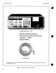
FG-30 / FG-32
USER'S MANUAL
I. NOTICE BEFORE OPERATION
1
II. FG-30 GENERAL
3
III. FG-30 SPECIFICATIONS
4
IV. FG-30 FRONT PANEL DESCRIPTION
6
V. FG-30 OPERATING INSTRUCTIONS
7
VI. FG-32 GENERAL
10
VII. FG-32 SPECIFICATIONS
11
VIII. FG-32 FRONT PANEL DESCRIPTION
13
IX. FG-32 OPERATING INSTRUCTIONS
15
X. SCHEMATICS & PARTS LIST
19
I. NOTICE BEFORE OPERATION
1. Unpack the instrument:
After receipt of the instrument, immediately unpack and inspect it for any shipping damage or missing accessories.
If any sign of damage or missing accessories are found, immediately notify the dealer.
2. Environmental:
These instruments are designed for "Indoor Use" only. Normally, operational temperature of these instruments is 10℃
to 40℃(50℉ to 104℉). Operation outside of this temperature range may cause damage to the circuits.
Do not use these instruments in a place where strong magnetic or electric fields exist. Such fields may adversely effect
your measurements.
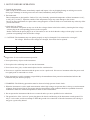
3. Check the Line Voltage:
These instruments can operate on any one of the line voltages shown in the below table by inserting the line voltage
selector plug in the corresponding position on the rear panel.
Before connection the power plug to an AC line outlet, be sure to check that the voltage selector plug is set in the
position corresponding to the desired line voltage.
!!! CAUTION: The instrument may not operate properly or may be damaged if it is connected to a wrong AC
line voltage. Whenever line voltages are changed, fuses must also be replaced.
SELECTOR
115V
230V
●
LINE VOLTAGE
100~125V 50/60Hz
220~240V 50/60Hz
FUSE
600mA
300mA
Suggestions for successful instrument operation:
1. Never place heavy objects on the instrument.
2. Never place a hot soldering iron on or near the instrument.
3. Never insert wires, pins, or other metal objects into the ventilation fan.
4. Never move or pull the instrument with the power cord or a probe cord. Never move instrument when the power cord
or a signal probe is connected to a circuit.
5. If the instrument is used in a manner not specified by the manufacturer then protection mechanisms built into the
instrument may not function properly.
!!! WARNING: The following precautions must be observed to help prevent electric shock:
1. When the instrument is used to make measurements where high voltages are present, there is always a certain amount
of danger from electrical shock. The person using the instrument in such condition should be a qualified electronics
technician or otherwise trained and qualified to work in such circumstances.
2. Do not operate the instrument with the cover removed unless you are a qualified service technician.
3. The ground wire of the 3-wire AC power plug places the chassis and housing of the instrument at earth ground. Use
only a 3-wire outlet, and do not attempt to defeat the ground wire connection or float the instrument, since doing so
may pose a great safety hazard.
1
4. Do not obstruct the ventilation holes in the rear panel, as this will increase the internal temperature.
5. Never apply external voltage to the output BNC of the instrument.
6. Excessive voltage applied to the input BNC may damage the instrument.
2
II. FG-30 GENERAL
DESCRIPTION:
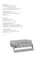
The FG-30 is a multi-purpose, highly reliable, and low cost 3 MHz sweep function generator. While being
rugged and easy to use, it also provides many convenient features which make it an ideal instrument for electronics,
education, production, and research and development laboratories.
FEATURES:
(1). Six output waveforms -- Unlike conventional function generators on the market, the FG-30 provides 6 waveforms.
(2). Pulse generator -- Adjustable pulse width from 100ns to 0.4s make the FG-30 an ideal instrument for audio, Video,
and other basic electronic circuit applications.
(3). Sweep generator -- Besides the outer VCF input function, the FG-30 provides variable internal linear sweep and
log sweep with sweep range over 1000:1 and sweep rate from 10ms to 5s. Also, the FG-30 provides single sweep or
synchro-sweep output function.
(4). Excellent heat dissipation -- This function generator was based on the continuous charge-discharge of a capacitor to
produce the output waveform. Any change on the capacitor value will cause a different frequency to be generated.
Temperature rises within the instrument will also change the capacitance. Thus keeping the inner temperature constant
becomes a very important factor on the stability of the frequency generated.
(5). Safety -- FG-30 meets the regulations of CE, GS, UL etc.
3
III. FG-30 SPECIFICATIONS
1. GENERAL SPECIFICATIONS:
Frequency: 0.5Hz ~ 3MHz in 6 steps, controlled by rotary switch.
Output Waveform: Sine, Square, Triangle, Ramp, Positive Pulse and Negative Pulse; 6 waveforms total.
Stability: 0.1% - 15minutes after power-on.
0.2% - 24hrs after power-on.
DC Offset: Continuous Adjustment, ?10V at no-load or ?5V at 50 load.
Limits of Operation: 0℃~40℃,10~80%R.H.
Storage Environment: -20℃~70℃,0~90%R.H.
Power source: AC 115V (±10%)50/60HZ,FUSE:600mA
AC 230V (±10%)50/60HZ,FUSE:300mA
Power Consumption: 25W
Dimensions: 27.5 x 9.0 x.30.0 cm
Weight: 2.5Kg Net.
Accessory: Power cord, manual.
2. RAMP WAVE:
Frequency: 0.5Hz - 2.5MHz
Symmetry: 80% (rise wave) to 20% (fall wave), < 5%, 1Hz ~ 100KHz.
Rise Wave Linearity: < 2%, 1Hz - 100KHz.
3. TRIANGLE WAVE:
Frequency: 0.5Hz - 3MHz.
Symmetry: 50% (rise wave) to 50% (fall wave), < 2%, 1Hz ~ 100KHz.
Linearity: < 1%, 1Hz ~ 100KHz.
4. SINE WAVE:
Frequency: 0.5Hz ~ 3MHz.
Distortion: < 2%, 1Hz ~ 100KHz.
Harmonic Ratio: < 30dB, 100KHz ~ 3MHz.
Frequency Response: < 0.1dB up to 100KHz.
< 1dB 100KHz to 3MHz.
5. SQUARE WAVE:
Frequency: 0.5Hz ~ 3MHz.
Symmetry: 50% (positive half) to 50% (negative half), < 2%, 1Hz ~ 100KHz.
Rise Time: < 60ns.
6. POSITIVE PULSE:
Frequency: 0.5Hz ~ 2.5MHz.
Width: 0.4sec ~ 100ns continuous adjustment.
Symmetry: 20% to 80%, < 5%, 1Hz ~ 100KHz.
Rise Time: < 60ns.
7. NEGATIVE PULSE:
Frequency: 0.5Hz ~ 2.5MHz.
Width: 0.4sec ~ 100ns.
Symmetry: 80% to 20%, < 5%, 1Hz ~ 100KHz.
Fall Time: < 60ns.
4
8. MAIN OUTPUT:
Output Impedance: 50Ω, < 2% Accuracy.
Max. output: 20 Vp-p (No load), ±1V?
10 Vp-p (50Ω load),±0.5V ?
Min. output: 0.1Vp-p (No load) and 0.05V (50Ω load)
Attenuator: one -20dB switch, < 2% Accuracy.
9. SYNCHRONOUS OUTPUT:
Output Impedance: 50Ω, < 2% Accuracy.
Output Level: TTL level, > 3Vp-p fixed amplitude.
Fanout: > 20.
Rise Time: < 30ns.
10. VCF INPUT:
Input Impedance: 0 ~ 10V.
Input Frequency: DC ~ 1KHz.
Input Frequency Variance: 1:1 to 1:1000.
11. SWEEP SYNCHRONOUS OUTPUT:
Output Impedance: 1KHz, < 20%.
Output Waveform: Linear or Log Sweep Ramp Wave.
Output Amplitude: 10Vp-p (No load) or 5Vp-p (1KΩ load)
Output Frequency: Continuous adjustment, 0.2Hz ~ 100Hz.
12. SWEEP GENERATOR:
Sweep Form: Linear or Log switchable.
Sweep Speed: 5sec ~ 10ms, continuous adjustment.
Sweep Width: 1:1 ~ 1:100
5
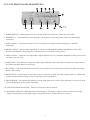
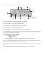
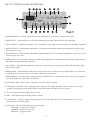
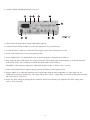
IV. FG-30 FRONT PANEL DESCRIPTION
1. POWER SWITCH -- When pushed "ON" the switch will light the power pilot "LED" above the switch.
2. FREQUENCY -- Fine adjustment for the frequency. The frequency will be the product of the scale indicated by
(2) and (11).
3. SYNC OUTPUT -- Synchronous Output. A TTL level Square wave output with same frequency as the Main
output BNC.
4. SWEEP OUTPUT -- Sweep signal output BNC. It will operate independently whether the SWEEP is ON or OFF;
the BNC will output the sweep ramp wave. The frequency is controlled by sweep rate (8).
5. MAIN OUTPUT -- Function wave output BNC. Output impedance is 50Ω, maximum amplitude is 20Vp-p for no-load
and 10Vp-p for 50Ω load.
6. AMPLITUDE -- Turn the knob to adjust the output signal amplitude. Pull out the knob to attenuate the output 10 times.
This affects the Main output (5) signal only.
7. DC OFFSET -- The knob controls the bias circuit, it is set at OFF position in normal use. Pull "ON" and turn to adjust
the DC offset voltage.
8. SWEEP RATE -- Turn this knob to adjust the sweep rate from 5sec to 10ms, the sweep output is BNC (4). If this knob
is pulled out then the main output (5) and sweep output (4) are synchronous.
9. SWEEP WIDTH -- Turn this knob to adjust the sweep width. Push in for a linear sweep, pull out for a log sweep. Knob
(8) must be pulled out or this control is disabled.
10. FUNCTION WAVE SELECTOR -- Turn this to select the output waveform.
11. FREQUENCY RANGE -- Main adjustment of the frequency. The output frequency will be 10 times on each step
changed. The frequency of the output signal is the product of the scale indicated by (2) and (11).
6
V. FG-30 OPERATING INSTRUCTIONS
!!! WARNING: Before applying power to your FG-30, make sure that the input voltage setting is correct for your
power source.
!!! CAUTION: All the knobs on the FG-30 are set at "push" position unless specially marked "pull".
A: FUNCTION GENERATOR (Ref. to Fig 5-1)
1. Check that the AC line voltage selector plug on the rear panel of your FG-30 is in the correct position for the AC
line voltage.
2. Switch on the power switch and make sure that the power pilot LED is lit.
3. Connect the OUTPUT BNC (4) of the FG-30 to the CH1 INPUT BNC of your Oscilloscope. Adjust your
Oscilloscope for best view of the waveform.
4. Connect the SYNC OUTPUT BNC (5) to the CH2 INPUT BNC of your Oscilloscope and set the TRIG source of your
Oscilloscope at CH2 position.
5. Turn the FREQUENCY knob (6) of FG-30 from 0.05 to 3.0 position and check the waveform displayed on your
Oscilloscope. The frequency will vary slowly on each step.
6. Turn the RANGE knob (7) clock-wise from 10 to 1M. The frequency will increase 10 times on each step. If turning the
knob counter-clock-wise from 1M to 10, the frequency will reduce 10 times on each step.
7. Turn the FUNCTION knob (8) to change the waveform generated by FG-30 and displayed on oscilloscope. CH1 will
display the waveform as indicated by the FUNCTION knob (8) of FG-30, However, CH2 will always display a TTL
square wave only, but the frequency of CH2 will synchronously change as CH1 changes.
8. Turn the AMPL knob (9). The amplitude of CH1 on your Oscilloscope will change but CH2 will not. Pull out the knob,
the amplitude of CH1 will be reduced 10 times but CH2 will remain unchanged.
9. Turn the OFFSET knob (10), the display on the Oscilloscope will be unchanged. Pull out the knob. The display of CH1
on the Oscilloscope will now be affected by the DC offset voltage as controlled from +10V to -10V by turning the knob.
The CH2 display will be unaffected. Note that the CH1 display may be cut off if the DC offset voltage is too high.
7
B: SWEEP GENERATOR (Ref. to Fig.5-2)
1. Switch on the FG-30 and connect it to your oscilloscope, Main output (3) to CH1.
2. Connect the SWEEP output (4) BNC to CH2.
3. Set the RANGE (5) of FG-30 at 100K position.
4. Set the FREQUENCY (6) of FG-30 at 1.0 position.
5. Set the FUNCTION (7) of FG-30 at sine wave.
6. Turn the SWEEP RATE (8) knob, the display of CH1 will remain unchanged. Only the display of CH2 will be affected.
Since knob (8) is pushed in the sweep output will operate independently. Pull out knob (8) to set FG-30 SWEEP ON
and turn the knob to set the sweep rate from 5sec. to 10ms. Both CH1 and CH2 displays will be affected.
!!! NOTE: After "PULL SWEEP ON", the trigger source of the oscilloscope must be changed to CH1.
7. Turn the SWEEP WIDTH (9) to adjust the sweep width according to the display of CH1 on your oscilloscope to set the
sweep width and sweep rate. Set the FREQUENCY knob (6) at 0.05 to have the maximum sweep width (>100 times). It is
most commonly used when doing audio or circuit bandwidth testing. Pull out knob (9), the sweep mode will be changed
from linear sweep to Log sweep. The waveform displayed on CH1 will be log form.
8. SYNC OUTPUT (10)-- The BNC will synchronously output a TTL signal to use as a signal source for an oscilloscope
or counter, etc.
9. AMPL (11) -- Turn this knob to adjust the amplitude of the signal from the Main output.
10. OFFSET KNOB (12) -- This sets the DC offset voltage of the signal from the Main output. This knob will operate
only at the "PULL" position.
8
C. PULSE Generator (Ref. to Fig. 5-3)
1. Switch "ON" the power switch (1) and make sure the pilot "LED" been lit.
2. Connect the output BNC (3) to CH1 input of your Oscilloscope.
3. Connect the "SYNC OUT" (4) BNC to CH2 input of your oscilloscope.
4. Set the "FUNCTION" (5) selector at positive pulse position.
5. Set the "RANGE" (6) at the desired frequency. In this example, set at 100K position.
6. Set the "FREQUENCY" (7) at the desired frequency. The frequency will be the product of the settings indicated by
(6) and (7). In this example set (7) at 1.0 position.
Example: The frequency: 100K x 1.0 = 100KHz
The pulse width: (1/frequency) x 15%
=(1/100KHz) x 15%
= 1.5uS
The pulse output from "SYNC OUTPUT" TO CH2 will be the same 1.5uS width TTL pulse.
7. Adjust the "AMPL" (8) knob to adjust the amplitude of the output pulse. Or "PULL" out this knob to attenuate the
output signal to 1/10, but the CH2 "SYNC OUTPUT" will not affected.
8. PULL OUT the "OFFSET" (9) knob and turn to adjust the DC offset voltage if necessary. CH2 will not be affected
by this.
9. Set the "FUNCTION" (5) selector to negative pulse and operate as steps 5, 6, 7, and 8 as above.
9
VI. FG-32 GENERAL
DESCRIPTION:
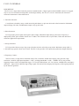
The FG-32 is a super deluxe function generator combined with a 5 digit, high resolution 60MHz counter. It is rugged,
easy to use, has excellent heat dissipation, and has high stability. The FG-32 is a 4-in-1 instrument, the 4 kinds of
electronic instruments are described below.
1. Function Generator:
6 waveforms selected by rotary switch instead of push-button, to prevent mis-touch or bad connection. Maximum
output 20Vp-p (No-load), and Minimum output 0.1Vp-p (No-load).
2. Pulse Generator:
FG-32 provides positive pulse and negative pulse output, Maximum output 20Vp-p (No-load). Frequency is
displayed by LEDs, pulse width is from 0.4sec to 100ns. This will meet most of your Audio, Video and other basic
electronic application requirements.
3. Sweep Generator:
FG-32 provides linear sweep or log sweep selection switch to select the sweep mode. Maximum sweep width is
1:100 and sweep speed is from 5sec to 10ms. The FG-32 also provides VCF input and synchronous Output Function.
4. Frequency Counter:
The FG-32 has a 5-digit micro-controlled counter. FG-32 features include auto ranging, auto gate time, high
resolution --0.001Hz, high input impedance --1MΩ, and high bandwidth --0.2Hz ~ 60MHz. FG-32 also provides
triggering features such as an adjustable trigger ±2.5V with LED indicator, AC / DC selector, 100KHz filter, and input?
attenuator -- input x20 for 300Vrms high voltage signal. The unit will also display the frequency of the signal produced
by the function generator.
10
VII. FG-32 SPECIFICATIONS
1. GENERAL SPECIFICATIONS:
A: Generator
Frequency -- 0.5Hz ~ 3MHz with 5-digit LED display, Max. resolution 0.001Hz in 6 steps.
Waveform output -- Sine, Square, Triangle, Ramp, Positive Pulse and Negative Pulse; 6 waveforms total.
Stability -- 0.1% ~ 15 minutes after power-on.
0.2% ~ 24hrs after power-on.
B: Counter
Display -- 5 digits 0.36" red LED.
Max. Resolution -- 0.001Hz.
Display unit -- Hz / KHz Automatically controlled by CPU.
C: Common Specification
Limits of operation -- 0℃~40℃,10%~80%R.H.
Storage Environment -- -20℃~70℃,0%~90%R.H.
Power consumption -- 25W.
Power source -- AC 115V (±10%)50/60Hz,FUSE:600mA?
AC 230V (±10%)50/60Hz,FUSE:300mA?
Ventilation -- DC 12V / 100mA Fan.
Dimensions -- 275 x 90 x 300mm
Weight -- 2.5Kg Net.
Accessory -- Power cord, operating manual.
2. RAMP WAVE:
Frequency: 0.5Hz ~ 2.5MHz, 5-digit LED display, Max. resolution 0.001Hz, 6 steps selected by rotary switch.
Symmetry: 80% (Rise wave) to 20% (Fall wave), < 5%, 1Hz ~ 100KHz.
Rise Wave Linearity: < 2%, 1Hz ~ 100KHz.
3. TRIANGLE WAVE:
Frequency: 0.5Hz ~ 3MHz, 5-digit LED display, Max. resolution 0.001Hz
Symmetry: 50% (Rise wave) to 50% (Fall wave), < 2%, 1Hz ~ 100KHz.
4. SINE WAVE:
Frequency: 0.5Hz ~ 3MHz, 5-digit LED display, Max. resolution 0.001Hz.
Distortion: < 2%, 1Hz ~ 100KHz.
Harmonic Ratio: < 30dB, 100KHz ~ 3MHz
Frequency Response: < 0.1dB, up to 100KHz.
< 1dB, 100KHz to 3MHz.
5. SQUARE WAVE:
Frequency: 0.5Hz ~ 3MHz, 5-digit LED display, Max. resolution 0.001Hz.
Symmetry: 50% (Positive half) to 50% (Negative half). < 2%, 1Hz ~ 100KHz
Rise Time: < 60ns.
6. POSITIVE PULSE:
Frequency: 0.5Hz ~ 2.5MHz, 5-digit LED display.
Width: 0.4sec ~ 100ns, continuous adjustment.
Symmetry: 20% to 80%, < 5%, 1Hz ~ 100KHz.
Rise Time: < 60ns.
7. NEGATIVE PULSE:
Frequency: 0.5Hz ~ 2.5MHz, 5-digit LED display, Max. resolution 0.001Hz.
Width: 0.4sec ~ 100ns.
Symmetry: 80% to 20%, < 5%, 1Hz ~ 100KHz.
Fall Time: < 60ns.
11
8. MAIN OUTPUT:
Output Impedance: 50W, < 2% Accuracy
Max. Output: 20Vp-p (No-load),±1V ?
10Vp-p (50Ω load)±0.5V ?
Min. Output: 0.1Vp-p (No-load), or 0.05Vp-p (50Ω load)
Attenuator: One -20dB Attenuator, < 2% Accuracy
9. SYNCHRONOUS OUTPUT:
Output Impedance: 50Ω, < 2%, Accuracy.
Output Level: TTL level, > 3Vp-p fixed amplitude.
Fan Out: > 20
Rise Time: < 30nS.
10. VCF INPUT:
Input Voltage: 0 ~ 10V
Input Frequency: DC ~ 1KHz
Input Frequency Variance: 1:1 to 1:1000
11. SWEEP SYNCHRONOUS OUTPUT:
Output Impedance: 1KHz, < 2%
Output Waveform: Linear or Log sweep ramp wave.
Output Amplitude: 10Vp-p (No load) or 5Vp-p (1KΩ load)
Output Frequency: 0.2Hz ~ 100Hz continuous adjustment.
12. SWEEP GENERATOR:
Sweep Form: Linear or Log switchable.
Sweep Speed: 5sec ~ 10ms, continuous adjustment.
Sweep Width: 1:1 ~ 1:100
13. COUNTER:
Display: 5 digits, 0.36" red LED display.
Max. Resolution: 0.001Hz
Display unit: Hz / KHz, Auto range.
Time base: 20MHz
Temperature coefficient: < 10ppm / 蚓
Accuracy: < 0.002% ?
Power Supply: +5V, 160mA
Internal Counter:
Range: Auto range with 4 resolutions, 0.001Hz / 0.01Hz / 0.001KHz / 0.01KHz, Auto control by CPU.
Display: 0.500Hz ~ 3000.0KHz, Auto select by CPU.
Gate time: Variable, 0.25sec ~ 2sec, Auto - setting.
Min. display digits: 4 digits.
External Counter:
Max. Input Voltage: < 250Vrms
Input Impedance: 1MΩ, < 2%
Input Frequency: 0.2Hz ~ 60MHz
Attenuator: *20 (-26dB) Attenuator
Coupling: AC (HF) -- For >100KHz frequency.
DC (LF) -- With 100KHz filter, for frequency <100KHz
Range: The same as internal counter.
Min. display digits: 4 digits.
Gate Time: 0.25sec ~ 10sec, Auto - setting, depends on the input frequency
Sensitivity: < 30mVrms (1MHz)
12
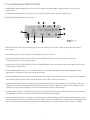
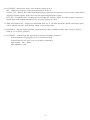
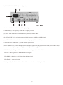
VIII. FG-32 FRONT PANEL DESCRIPTION
1. POWER SWITCH -- Push the switch "ON" and the LED digits (14) will light to indicate power "ON".
2. FREQUENCY -- Turn this knob to set the desired frequency generated. This knob is for fine adjustment.
3. SYNC OUTPUT -- Synchronous Output. A TTL level Square wave output with same frequency as the Main output BNC.
4. SWEEP OUTPUT -- Sweep signal output BNC. It will operate individually whether the instrument was under sweep
mode operation or not.
5. MAIN OUTPUT -- Function wave output BNC. Output impedance is 50Ω, maximum amplitude is 20Vp-p for no-load
and 10Vp-p for 50Ω load.
6. AMPLITUDE -- Turn the knob to adjust the output signal amplitude. Pull out the knob to attenuate the output 10 times.
This affects the Main output (5) signal only.
7. DC OFFSET -- The knob controls the bias circuit, it is set at OFF position in normal use. Pull "ON" and turn to adjust
the DC offset voltage.
8. SWEEP RATE -- Turn this knob to adjust the sweep rate from 5sec to 25ms, the sweep output is BNC (4). If this knob
is pulled out then the main output (5) and sweep output (4) are synchronous.
9. SWEEP WIDTH -- Turn this knob to adjust the sweep width. Push in for a linear sweep, pull out for a log sweep. Knob
(8) must be pulled out or this control is disabled.
10. FUNCTION WAVE SELECTOR -- Turn this to select the output waveform.
11. FREQUENCY RANGE -- Main adjustment of the frequency. The output frequency will be 10 times on each step
changed. The frequency of the output signal is the product of the scale indicated by (2) and (11).
12. Hz -- the LED lit means the display units are "Hz".
13. KHz -- the LED lit means the display units are "KHz".
14. LED DIGITS -- 5 digits to indicate frequency generated or EXT input. The units will be indicated by (12) or (13)
selected by the CPU automatically.
15. EXT-TRIG -- The green LED indicates trigger condition.
LED Light -- Trigger level too high.
LED Dark -- Trigger level too low.
LED Flash -- Triggering state.
13
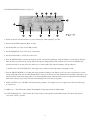
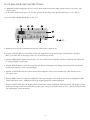
16. COUPLING -- Indicates the source of the frequency display by (14).
INT -- Displays the frequency of the signal generated by the FG-32.
EXT AC / HF -- Displays the external input high frequency signal. Set at this position to strain out DC signal and low
frequency harmonic signals. Input will be only the expected high frequency signal.
EXT - DC / LF 100KHz Filter -- Displays the external input low frequency signal. Set at this position to strain out
signals higher than 100KHz and make the low frequency signal more stable.
17. TRIG PULL INPUT *20 -- Trigger level adjustment from +2V to -2V. When this knob is pulled out the input signal
will be attenuated 20 times, thus the input voltage can be 250Vp-p Max.
18. EXT-INPUT -- External signal input BNC. Input frequency 0.2Hz to 60MHz and Max. input voltage is 250Vp-p
(when (17) is at "PULL" position).
19. VCF-INPUT -- External input DC signal used to control the frequency generated.
External input AC sweep signal to use it as an External sweep.
External input AC sine wave to use it as frequency modulation.
Input signal 0 ~ 10V, < 1KHz.
Input impedance - 1KΩ.
14
IX. GF-8046 OPERATION INSTRUCTIONS
!!! WARNING: Before applying power to your GF-8046, make sure that the input voltage setting is correct for your
power source.
!!! CAUTION: All the knobs are set at " PUSH " position on operation if not special marked to be set at " PULL ".
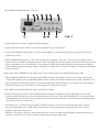
(A). FUNCTION GENERATOR (Ref. to Fig. 9-1)
1. Push the power switch on and make sure that the LEDs of the 5 digits are lit.
2. Connect OUTPUT BNC (4) of GF-8046 to the CH1 input BNC of your Oscilloscope, and the SYNC OUTPUT
BNC (5) to CH2, and set the trigger source of your oscilloscope at CH2.
3. Turn the FREQUENCY knob (6) from 0.05 to 3.0. You will find the LED display and the oscilloscope waveform will
be changed slightly on each step.
4. Turn the RANGE knob (7) from 10 to 1M. You will find the LED display will change 10 times on each step and the
oscilloscope frequency varies correspondingly.
5. Turn the FUNCTION knob (8) to select the waveform output to CH1 of your Oscilloscope. CH2 will always be a
TTL square wave.
6. Turn the AMPL knob (9) to adjust the amplitude of the signal output to CH1. Pull out the knob, the amplitude of CH1
will be reduced 10 times ( -20dB) but CH2 (Sync output signal) will remain unchanged.
7. Turn the OFFSET knob (10), the display on the Oscilloscope will be unchanged. Pull out the knob. The display of CH1
on the Oscilloscope will now be affected by the DC offset voltage as controlled from +10V to -10V by turning the knob.
The CH2 display will be unaffected.
15
(B). SWEEP GENERATOR (Ref. to Fig 9-2)
1. Switch on the FG-32 and the 5 digit LED display lights up.
2. Connect the main OUTPUT BNC (4) to the CH1 input BNC of you Oscilloscope.
3. Connect the SWEEP OUTPUT BNC (5) to the CH2 input BNC of your Oscilloscope and set the trigger source of the
oscilloscope at CH2.
4. Turn the SWEEP RATE knob (6), CH2 of the oscilloscope will display a linear saw - tooth wave, the frequency can be
varied from 5sec to 10mS by turning the knob (6). CH1 will display the wave according to the FUNCTION switch position.
PULL out the knob (6) to set "SWEEP ON". The waveform of CH2 will remain unchanged, but the displayed frequency
can be varied by turning the frequency knobs. The display of CH1 will be a sweep wave, and the sweep speed will depend
on the sweep rate.
NOTE: After "PULL SWEEP ON", the trigger source of the oscilloscope must be changed from CH2 to CH1.
7. Turn the SWEEP WIDTH (9) to adjust the sweep width according to the display of CH1 on your oscilloscope to set the
sweep width and sweep rate. Set the FREQUENCY knob (6) at 0.05 to have the maximum sweep width (>100 times). It is
most commonly used when doing audio or circuit bandwidth testing. Pull out knob (9), the sweep mode will be changed
from linear sweep to Log sweep. The waveform displayed on CH1 will be log form.
6. The AMPL (8) and FUNCTION (10) knobs will operate normally.
7. Before activating sweep mode ("PULL SWEEP ON") the frequency is displayed on the 5 LED digits as in Function
Generator mode, this frequency will be the start frequency of the sweep. After "PULL SWEEP ON", the sweep condition
including frequency, waveform, and sweep mode etc. will be observed on the CRT of the Oscilloscope. The LED display
on the FG-32 will vary continuously.
8. VCF INPUT (11) -- Set the sweep rate switch at "PUSH" position to set FG-32 to normal generator mode. Connect
the sweep output BNC to VCF INPUT BNC and check the waveform displayed on the scope CH1. The waveform
displayed will be the sweep wave.
When the VCF input is a sine wave from another generator, the FG-32 output will be frequency modulated. Be sure the
frequency of the basic wave (FG-32 output) is higher than the external input signal.
16
(C). PULSE WAVE GENERATOR (Ref. to Fig.9-3)
1. Switch on the GF-8046 and the 5 digit LED display lights up.
2. Connect the main OUTPUT BNC (4) to the CH1 input BNC of you Oscilloscope.
3. Connect the SYNC output (4) to CH2 and set the trigger source of the Oscilloscope on CH2.
4. Set the FUNCTION knob (5) on positive pulse position.
5. Set the FREQUENCY (7) and RANGE (6) to the desired frequency, displayed on the LED (2).
6. Pulse width: the pulse width equals 15% of the total period of the output signal. If the frequency is in Hz then the pulse
width will be in Sec. If the frequency is in KHz then pulse width will be in mS etc.
EXAMPLE: If the frequency displayed is 1KHz then the pulse width = 1/1KHz * 15% = 0.15mS.
7. Set the FUNCTION knob on negative pulse position and similarly test the negative pulse.
8. Turn the AMPL (9) to adjust the amplitude of the signal output from the main output BNC (3). This signal will be
-20dB when the knob (9) is pulled out. The signal output from " SYNC " output BNC (4) will not be affected by this knob
and will always be a TTL level.
9. Set the DC offset voltage by pulling out the "OFFSET" knob (10) and turning it to adjust the DC offset voltage from
+10V to -10V as desired.
17
(D). FREQUENCY COUNTER (Ref. to Fig. 9-4)
1. Switch on the FG-32 and the 5 digit LED display lights up.
2. COUPLING (3): The frequency counter has 3 coupling options.
(a). INT -- To be used with the internal function generator, 0.5Hz to 3MHz.
(b). EXT AC / HF: To be used with an external high frequency (100KHz to 60MHz) signal.
(c). EXT DC / LF: To be used with an external low frequency (0.2Hz to 100KHz) signal.
3. Connect the EXT INPUT BNC (4) to the external signal source.
4. Set the TRIG level (5) to meet the input signal. If the input signal is very large, pull out the knob (PULL INPUT *20) to
have stable counting. Max. input is 20Vp-p, or 600Vp-p with *20 engaged.
5. EXT TRIG'D (6) -- The green LED will indicate the operating condition of the FG-32.
LED LIT -- the trigger level is higher than the input signal.
LED DARK -- the trigger level is lower than the input signal.
LED FLASH -- normal triggering.
6. Display unit (7): The FG-32 will be on Hz or KHz automatically controlled by the CPU.
18