1
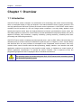
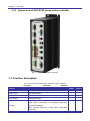
GUC-ECAT SERIES USER’S GUIDE Beta Version 2014.11 www.googoltech.com © 2014 Googol Technology. All rights reserved Copyright Statement Copyright Statement Googol Technology Ltd. All rights reserved. Googol Technology Ltd. (Googol Technology hereafter) reserves the right to modify the products and product specifications described in this manual without advance notice. Googol Technology will not take responsibility for any direct, indirect, consequential or liability caused damage by improperly using of this manual and the product. Googol Technology owns the patent, copyright or any other intellectual property rights of this product and the related software. No one shall duplicate, reproduce, process or use this product and its parts, unless authorized by Googol Technology. Machinery in motion can be dangerous! It is the user’s responsibility to design effective error handling and safety protection methods as part of the machinery. Googol Technology shall not be liable or responsible for any incidental or consequential damages. Contact Us Googol Technology (Shenzhen) Ltd. Googol Technology (HK) Ltd. Address: 2nd Floor, West Wing, IER Building (PKU-HKUST Shenzhen Hong Kong Institution) High-tech Industrial Park, Nanshan, Shenzhen, PRC Postal Code: 518057 Address: Unit 1008-09, 10/F C-Bons International Center, 108 Wai Yip Street, Kwun Tong, Kowloon, Hong Kong Tel.: +(86) 755-26970817, 755-26970824, 755-26737236 Fax: +(86) 755- 26970821 E-mail: [email protected] URL http://www.googoltech.com.cn Tel.: +(852) 2358-1033 Fax: +(852 )2719-8399 E-mail: [email protected] URL: http://www.googoltech.com 1 © 2014 Googol Technology. All rights reserved Document Version Document Version Version Date 1.0 2014-11-30 2 © 2014 Googol Technology. All rights reserved Foreword Foreword Thank you for selecting Googol Technology motion controller To repay user, we will help you establish your own control system, by providing our first-class motion controller, perfect after-sale services, and high-efficiency technical support. More information about products of Googol Technology Googol Technology’s web site is http://www.googoltech.com. You can get more information about the company and products on our website, including company profile, product introduction, technical support, product recently released. You can also get more information about the company and products through the phone: +(86) 755-26970817. Technical support and after-sale services To get our technical support and after-sale services: E-mail: [email protected] Tel.: +(86) 755 2697-0843 Addr: Googol Technology (SZ) Ltd 2nd Floor, West Wing, IER Building (PKU-HKUST Shenzhen Hong Kong Institution) High-tech Industrial Park, Nanshan, Shenzhen, PRC. Postal Code: 518057 Usage of this User’s Guide This guide will help the user understand the basic architecture of GUC-ECAT series of motion controllers, and learn how to install the motion controller, wire the controller with the motor control system and conduct the basic debugging of the motion control system. Users of this User’s Cuide This guide is suitable for the one who have engineering background, basic hardware knowledge, and good understanding of motion control. Main Contents of this Programming Manual This guide consists of six chapters. Introduce constitute, installment, link, technical parameters, tuning, troubleshooting etc. of GUC-ECAT series Motion Controller in detail. 3 © 2014 Googol Technology. All rights reserved Foreword Related documents Programming with GUC-ECAT series motion controller, please refer "Advanced Programming Manual of GUC-ECAT Series Motion Controller” and " Programming Manual of GUC-ECAT Series Motion Control Box” provided together with our product. 4 © 2014 Googol Technology. All rights reserved Contents Contents Copyright Statement 1 Contact Us 1 Document Version 2 Foreword 3 Contents 5 Chapter 1 Overview 7 1.1 Introduction 1.2 Model description 1.2.1 GUC-ECAT Series Motion Controllers 1.2.2 Appearance of GUC-ECAT series motion controller 1.3 Function description Chapter 2 Quick Start 7 8 8 9 9 11 2.1 Open the Package and Check 11 2.2 Installation Site 11 2.3 Preparation 11 2.4 Installation Procedures 12 2.4.1 Step 1: Connect GUC motion controller with standard input/output device and +24V DC power. Turn on the power 12 2.4.2 Step 2: Install operating system on the motion controller 13 2.4.3 Step3: Install Windows drivers of the motion controller (only for Windows environment) 19 2.4.4 Step4: Establish communication between the host and the motion controller (only for Windows environment) 23 2.4.5 Step 5: Connect the motor with driver 23 2.4.6 Step 6: Connect the controller with the servo drivers 24 Chapter 3 Hardware connection 25 3.1 Controller type description 3.2 Definition of special interface 25 26 Chapter 4 35 Test and Tune 5 © 2014 Googol Technology. All rights reserved Contents 4.1 Introduction 4.2 Quick use 4.2.1 Ensure the communication between controller and slave 4.2.2 Homing and limit 4.2.3 Local IO 4.2.4 Analog input and output 4.2.5 Auxiliary encode 4.2.6 Motion mode 4.2.7 Extended module 35 36 36 37 38 38 38 39 39 Chapter 5 40 Examples of Common Peripherals Connection 5.1 Inverter 5.2 Rotary encoder 40 41 Chapter 6 43 Appendix 6.1 Technical Specification 6.1.1 Overview 6.1.2 Control interface parameters 6.2 Troubleshooting 6.3 Make a USB boot disk 6.4 VC remote debug 6.4.1 VC++6.0 remote debug 6.4.2 Visual Studio remote debug 6.5 Dimension 43 43 44 48 51 56 56 58 63 6 © 2014 Googol Technology. All rights reserved Chapter 1 Overview Chapter 1 Overview 1.1 Introduction GUC-ECAT series motion controller is a combination of PC technology and motion control technology, which is developed based on CPU and chipset in Intel X86 architecture as the system processor, and use high performance DSP and FPGA as the motion control coprocessor. A GUC-ECAT series motion controller has full functions of a PC and Googol motion controllers, it not only widely applied in high speed point-to-point motion area and high-performance multi-axis synchronization motion areas, but also widely applied in common PC ,which makes it an ideal embedded development platform and can be applied to robotics, CNC machinery, carpentry machinery, printing machinery, assembly lines, laser processing and PCB milling machinery. GUC-ECAT series motion controllers provided general ports ( such as PS2, USB, VGA and LAN) and dedicated ports for motion control(The definitions of ports are given in Chapter 3). The C function library and Windows DLL are also provided to accomplish more complicated control functions. User may combine these control functions with the data processing, display interface, user interface and other application modules as required by some specific control system, to implement a control system of specific application requirements. To operate the motion controller, user is required to have the programming experience with C language or DLL in Windows environment. No operating system is provided along with GUC –ECAT series motion controllers, please use authorized operating system. 7 © 2014 Googol Technology. All rights reserved Chapter 1 Overview 1.2 Model description 1.2.1 GUC-ECAT Series Motion Controllers GUC - ECATXX - M23 - L2 - F4G Structure L2:Double terminal board structure Series symbol GUC:GUC Series Number of axis ECAT8 :8 axes ECAT64:64 axes CPU Type M23:CPU 1.66GHz, Memory : 2GB Electronic disk capacity F4G:4G DOM Note:M23(1000M network) Fig 1-1 Model description of GUC-T series Motion Controllers Common product model is illustrated in Fig 1-1, please refer to 3.1 for detailed description. Tab 1-1 Standard model of GUC-ECAT Description Model GUC-ECAT8-M23-L2-F4G 8 axes GUC-ECAT64-M23-L2-F4G 64 axes 8 © 2014 Googol Technology. All rights reserved Chapter 1 Overview 1.2.2 Appearance of GUC-ECAT series motion controller Fig 1-2 GUC-ECAT motion controller 1.3 Function description Tab 1-2 Function list of GUC-ECAT 8/64 axes motion controller √ Included - Excluded * Optional Features ECAT8 ECAT64 Sampling cycle 125 us (invariable) √ √ Control cycle 250 us(invariable) √ √ Analog output Scale: -10V to +10V √ √ Pulse output Differential output - - Encoder 4 channels(4 axes motion controllers) or 8 channels(8 axes motion controllers) of quadrupled frequency incremental encoder. Max. Counting frequency: 8 MHz (After quadrupled frequency) - - 9 © 2014 Googol Technology. All rights reserved Chapter 1 Overview Features ECAT8 ECAT64 √ √ Auxiliary encoder 2 channels(4 axes motion controllers)or 1 channel(8 axes motion controllers) of quadrupled incremental encoder; Max. Counting frequency: 8 MHz (After quadrupled). Limit switch Positive and negative limit switch of each axis with optical coupling isolation √ √ Home switch 1 channel of home switch of each axis with optical coupling isolation √ √ Driver alarm signal 1 channel of driver alarm signal of each axis with optical coupling isolation √ √ Driver enable signal 1 channel of driver enable signal of each axis with optical coupling isolation √ √ Driver reset signal 1 channel of driver reset signal of each axis with optical coupling isolation √ √ Arrival digital signal input 1 channel of arrival digital signal of each axis with optical coupling isolation √ √ General digital input 16 channels with optical coupling isolation √ √ General digital output 16 channels with optical coupling isolation √ √ Position compare output 2 channels(4 axes motion controllers)or 1 channel (8 axes motion controllers)differential position compare output signal(Note 1) - - Point to Point motion S-curve, T-curve, jog motion and electronic gear motion mode √ √ Synchronic motion Electric cam motion mode * * PT motion Position and time motion mode * * PVT motion Position, velocity and time motion mode * * Interpolate motion Linear interpolate motion √ √ Analog input Range: -10~+10V * * Motion program Directly run in motion controller √ √ Filter PID + Velocity feed-forward √ √ Extended module Support digital module and analog module √ √ Index signal of encoder √ √ Home switch signal √ √ Probe signal(Note2) - - Specify following error limit. √ √ Specify Output voltage saturation limit √ √ Hardware capture Safety feed-forward + Acceleration Note 1: Position compare output please refer to 10.11 of "Programming Manual of GUC-ECAT Series Motion Controller”. Note 2: Probe capture please refer to 7.6 of "Programming Manual of GTS Series Motion Controller” 10 © 2014 Googol Technology. All rights reserved Chapter 2 Quick Start Chapter 2 Quick Start 2.1 Open the Package and Check Please check and make sure the product on your hand is identical with the model you purchased before opening the packages, which can be found on the package. When the package is open, please take on the antistatic gloves provided by Googol Technology to check the accessories and make sure they are complete and same with the “packing list” or order contract. Check and make sure no mechanical damage on the motion controller. If there is mechanical damage on the controller, or any item missed in the package, please do not use the product and contact with Googol Technology or our distributor immediately. List of GUC-ECAT series 8/64 axes motion controller. (1) One GUC- ECAT series motion controller; (2) One product CD; (3) One antistatic gloves; (4) One Guarantee card; (5) One Certification. The list is for reference only, the actual term please refer to “packing list” or order contract. 2.2 Installation Site Motion controller should be far away from equipment and environment with high-power and strong electromagnetic interference. 2.3 Preparation Before installment, user has to prepare the following items: (1) +24V DC power (can’t be replaced by +12V direct supply); (2) Servo motor; (3) Driver and Power of GTHD-XXXXAEC2 series; (Currently supports driver of GTHD-XXXXAEC2 series only) (4) The quantity of network cable between GUC-ECAT controller and driver is the driver quantity +1, user supplied;(Please use the cable which rating consistent with TLA/EIA-568 standard STP 11 © 2014 Googol Technology. All rights reserved Chapter 2 Quick Start CAT-5E(UTP shielded wire or higher.) (5) Home switch, positive/negative limit switches (optional as needed); (6) Multimeter. 2.4 Installation Procedures Step 1: Connect GUC motion controller with standard input/output device and +24V DC power. Turn on the power; Step 2: Install operating system on the motion controller; Step3: Install Windows drivers of the motion controller (only for Windows environment); Step4: Establish communication between the host and the motion controller (only for Windows environment) Step 5: Connect the motor with driver; Step 6: Connect the controller with the servo drivers. 2.4.1 Step 1: Connect GUC motion controller with standard input/output device and +24V DC power. Turn on the power GUC-ECAT series motion controllers provide standard I/O ports (VGA, PS2 and USB) that used to set up a PC system. Users could use these ports to connect general I/O devices such as monitor, keyboard, mouse, etc. A DC power (24V, 3A output at least) is necessary for the PC system, thus the POWER port is used to connect the DC power supply. Two LED lights are on after power on indicating that the GUC motion controller is in operation. A PE (protect earth) port that connects with the shell of motion controller is also provided on the power port, with which users could connect external ground (shell, earth, etc.) and (or) internal ground (digital ground, +24V reference ground). Wiring of power is shown in Fig 2-1. 12 © 2014 Googol Technology. All rights reserved Chapter 2 Quick Start GUC ECAT Internal circuit +5V OGND DGND OVCC DC/DC +24V + 0V DC 24V - 0V User power supply SG PE Shell earth Earth Fig 2-1 Wiring of GUC-ECAT power supply To prevent electric shock and ensure normal operation of electric devices, please be sure to connect PE and earth. 2.4.2 Step 2: Install operating system on the motion controller After turning on the power of GUC motion controller according step1, please check if the operating system is installed. If no, user has to install the operating system as described as follows, otherwise please go to step 4 directly. Attention. Please make sure backup the important data and files in the GUC motion controller before installing the operating system. (1) Installation of Windows98/2000/XP 1) Prepare a USB CD-ROM and an installation CD of authorized Windows operating system. 2) Connect the USB CD-ROM with the GUC motion controller. Turn on the power. 3) Press DEL when starting the GUC motion controller to enter BIOS setting (Fig 2-2). Select Advanced BIOS Features and then press ENTER 13 © 2014 Googol Technology. All rights reserved Chapter 2 Quick Start Fig 2-2 4) BIOS setting 1 In Fig 2-3, set First Boot Device to USB-CDROM Fig 2-3 BIOS setting 2 5) Save BIOS setting. Restart the GUC motion controller and install operating system with the CD. 6) After the installation of operating system, please install drivers for Intel 852 chip and video card with the product CD. (Some operating system has already install the driver for video cared, to make sure display can startup normal after Illegal shutdown, it is suggested to install the driver as above). 7) Restart the GUC motion controller after the installation of driver is finished. By far the installation of operating system is finished. Users should use authorized software of operating system. Googol Technology is not liable for the legal issues that results from using pirate software. (2) Recovery of customized Windows C Only if users require customized WINCE, the product CD provides GHOST.exe and WINCE.gho. No such files are provided in standard products. If users need customized WINCE, please contact with Googol Tech. 1) Prepare a USB disk can be used as startup disk (on how to make a startup disk, please refer to 6.3), and copy GHOST.exe and WINCE.gho in the CD provided by Googol Tech. to it. 2) Connect the USB disk with the GUC motion controller, and turn on the power. 14 © 2014 Googol Technology. All rights reserved Chapter 2 Quick Start 3) Press DEL when starting GUC motion controller to enter BIOS setting. Set First Boot Device to USB-HDD (please refer to BIOS setting). 4) Save BIOS setting and restart GUC motion controller. 5) When GUC motion controller enter DOS interface, as shown in Fig 2-4, enter “ghost”, press “enter” to enter GHOST installation interface (Fig 2-5). Fig 2-4 Enter “ghost” in dos interface Fig 2-5 6) Installation interface of GHOST Click “ok” and enter Fig 2-6. 15 © 2014 Googol Technology. All rights reserved Chapter 2 Quick Start Fig 2-6 7) Installation interface of GHOST Select “Local”->”Disk”->”Form Image”, press enter, select “*.gho”(as shown in Fig 2-7). Fig 2-7 8) Select “*.gho” file After loading “*.GHO” file, it will appear dialog box as shown in Fig 2-8, select DOM a disk (GUC-T provide a 1G or 4G DOM disk, user should distinguish it by the size). 16 © 2014 Googol Technology. All rights reserved Chapter 2 Quick Start Fig 2-8 9) Select local destination driver Click “OK”, the destination drive details dialog box appears as shown in Fig 2-9. Fig 2-9 Destination drive details 10) Click “OK”, the question dialog box appears (as shown in Fig 2-10). 17 © 2014 Googol Technology. All rights reserved Chapter 2 Quick Start Fig 2-10 Confirm install dialog box 11) Click “Yes” and enter the Installation process interface. Fig 2-11 System installation process interface 12) After installation, it will appear dialog box as shown in Fig 2-12. 18 © 2014 Googol Technology. All rights reserved Chapter 2 Quick Start Fig 2-12 Completed installation dialog box 13) Extract USB disk, click “Reset Computer” to restart the computer and enter the WINCE interface. 2.4.3 Step3: Install Windows drivers of the motion controller (only for Windows environment) For DOS or WINCE operating system, please go to step4 directly Install Windows drivers of the motion controller (only for Windows environment) 1) After installing hardware and starting computer, Windows will automatically detect the motion controller, select “Install from a list or specific location(Advanced)”, click “Next”.As shown below. 19 © 2014 Googol Technology. All rights reserved Chapter 2 Quick Start Fig 2-13 2) Found new hardware wizard dialog box A Select “Don’t search. I will choose the driver to install”. Click “Next”. The panel as shown in Fig 2-14. Fig 2-14 Automatically or manually find drivers dialog box 3) After the previous step, the dialog box is to select the hardware model as shown in Fig 2-15. 20 © 2014 Googol Technology. All rights reserved Chapter 2 Quick Start Fig 2-15 4) Hardware model selection As shown in Fig 2-16, click “Have disk”, then click “Browse…” and choose GT800.INF in the path of “\Windows\Driver”. Fig 2-16 Find drivers path dialog box 21 © 2014 Googol Technology. All rights reserved Chapter 2 Quick Start Fig 2-17 5) Select the driver dialog box Select “GT800.INF”, click “Open”, as shown in Fig 2-17, it will turn to new dialog box as shown in Fig 2-16. Click “OK”, the wizard will automatically install the driver.Click “Finish” to complete the driver installation, as shown in Fig 2-18. 22 © 2014 Googol Technology. All rights reserved Chapter 2 Quick Start Fig 2-18 Driver installation completes dialog box 2.4.4 Step4: Establish communication between the host and the motion controller (only for Windows environment) For DOS operating system, please go to step5 directly. For user who use GUC-ECATXX-M23-L2-F4G series motion controller, please use the included software to test the communication of host and motion controller. Normal run of the testing software proves that the communication between the host and the motion controller is established successfully; otherwise it will pop up the message box “Connect to controller failed”, please refer to “Troubleshooting”, confirm what the trouble is, try again after trouble handled. If needed, please contact us. 2.4.5 Step 5: Connect the motor with driver For safety, we strongly suggest that user do not connect the motor with any mechanical device before installing and debugging the whole control system. Please check that there is no load with the motor. After setting proper parameters of driver and card and motor is under control, mechanical device could be connected, otherwise, it may cause serious consequential damages. Before connecting with the motor, please make sure the driver is not connected with the motion controller.Users must read the detailed instructions of driver and ensure proper connection. Test driver 23 © 2014 Googol Technology. All rights reserved Chapter 2 Quick Start and motor according to the manual to ensure that they work properly. 2.4.6 Step 6: Connect the controller with the servo drivers Turn off the power.Connect the GUC-ECAT controller with the servo drivers using the prepared network cable. GUC-ECATXX-M23-L2-F4G EHMI VGA KB&MS USB ENC0 ENC1 RS232 DIO LAN2 LAN1 EtherCAT EXTI/O AIO POWER EtherCAT Drivers(Note) Fig 2-19 Connection between GUC-ECATXX-M23-L2-F4G and EtherCATdrivers Note:Currently supports driver of GTHD-XXXXAEC2 series only. Other driver device support EtherCAT standard will be increased later. 24 © 2014 Googol Technology. All rights reserved Chapter 3 Hardware connection Chapter 3 Hardware connection 3.1 Controller type description GUC-ECATXX-M23-L2-F4G series motion controllers are universal EhterCAT network-based motion controllers for 8 axes and 64 axes. Two types controllers are shown in Tab 3-1, and the controller ports are shown inTab 3-2, Tab 3-3. Tab 3-1 GUC-ECATXX-M23-L2-F4G controller type description Controller types Type description GUC-ECAT8-M23-L2-F4G GUC-ECAT function; EtherCAT 8 axes(250us communication cycle)function; Kilomega network display; Double Ethernet; 8 channels digital input/output; 8 channels 12bit analog input; 2 channels 12bit analog output; 2 channels auxiliary encoder. GUC-ECAT64-M23-L2-F4G GUC-ECATfunction; EtherCAT 64axes(4mscommunication cycle)function; Kilomega network display; Double Ethernet; 8 channels digital input/output; 8 channels 12bit analog input 2 channels 12bit analog output; 2 channels auxiliary encoder. Controller types description: HD: (1)Kilomega network display, can connected to Googol Special display; (2)Double Ethernet,100M/1000M, adaptable. ECAT: comply with EtherCAT agreement. Please use the cable which rating consistent with TLA/EIA-568 standard STP CAT-5E(UTP shielded wire) or higher to connect to the fieldbus network..The interface type is standard RJ45. GUC-ECAT8-M23-L2-F4G Tab 3-2 GUC-ECAT8-M23-L2-F4G motion controller ports Port Function eHMI Kilomega network display port VGA VGA KB/MS Keyboard/Mouse 25 © 2014 Googol Technology. All rights reserved Chapter 3 Hardware connection USB Double-layer USB LAN1、LAN2 Dual Ethernet(1000M) RS232 General purpose COM. EXT I/O High speed IO extension port. ENC0、ENC1 Two auxiliary encoder interface DI\DO 8 channels general input/output (flexible configuration). AI\AO 8 channels 12bit analog input and 2 channels 12bit analog output EtherCAT Standard EtherCAT interface, control 8 axes in 250us communication cycle. POWER Power GUC-ECAT64-M23-L2-F4G Tab 3-3 GUC-ECAT8-M23-L2-F4G motion controller ports Port Function eHMI Kilomega network display port. VGA VGA KB/MS Keyboard/Mouse USB Double-layer USB LAN1、LAN2 Dual Ethernet(1000M) RS232 General purpose COM EXT I/O High speed IO extension port. ENC0、ENC1 Two auxiliary encoder interface DI\DO 8 channels general input/output (flexible configuration) AI\AO 8 channels 12bit analog input and 2 channels 12bit analog output EtherCAT Standard EtherCAT interface, control 64 axes in 4ms communication cycle. POWER Power 3.2 Definition of special interface GUC-ECAT controller provides all types of general interface and Special interface, general interface: VGA, KB&MS, USB, LAN, RS232, this user manual will not introduce these interface. The special interface is shown in Fig 3-1 and the definition is shown in Tab 3-4. 26 © 2014 Googol Technology. All rights reserved Chapter 3 Hardware connection 5 4 3 2 6 1 7 Fig 3-1 Interface of GUC-ECATcontroller Tab 3-4 Definition of special interface Label Port Description 1 POWER 2 AI/AO Analog input/output. 3 DI\DO General digital input /output. 4 ENC Auxiliary encoder port. 5 eHMI Kilomega network display port. 6 EtherCAT 7 EXTI/O Power. Standard EtherCAT port. High speed IO extension port. 27 © 2014 Googol Technology. All rights reserved Chapter 3 Hardware connection (1) POWER 1 5 Fig 3-2 Pin description of power port Tab 3-5 Description of power port Pin Port Description 1 24V +24V power 2 0V +24V reference ground 3 0V +24V reference ground 4 SG Digital ground 5 PE Protection earth (connect with earth) (2) AI\AO(Analog input/output) 1 9 13 7 8 16 Fig 3-3 Pin description of analog input/output As shown in Fig 3-3, there are 8 analog input channels(AI0~AI7) and 2 analog output channels(AO0~AO1).The interface design is easy to use the recommended UTP connection, which can reduce the interference. For the definitions of analog input/output port, please refer to Tab 3-6. Tab 3-6 Definitions of analog input/output port Pin Signal Description 1 AI0 Analog input 0 2 AI1 Analog input 1 3 AI2 Analog input 2 4 AI3 Analog input 3 5 AI4 Analog input 4 6 AI5 Analog input 5 13 AI6 Analog input 6 14 AI7 Analog input 7 9~12 AIGND Analog input reference ground Note 7 AO0 Analog output 0 28 © 2014 Googol Technology. All rights reserved Chapter 3 Hardware connection Pin Signal Description 8 AO1 Analog output 1 15、16 AOGND Analog output reference ground Note Note:AIGND、AOGND are isolated from ench other and are isolated from other ground too. 1) 2) 8 channels analog input can be used as single-ended(reference AIGND) input either as differential input(reference AIGND the same).When be use as differential input: AI0 and AI1 as one pair of differential input; AI2 and AI3 as one pair of differential input; AI4 and AI6 as one pair of differential input; AI5 and AI7 as one pair of differential input. The analog output value of AO0,AO1 is ranging in(-10V~10V), reference to AOGND. 1. 2. 3. 4. Analog input value ranging in(-10V~10V), please keep the value in the range, otherwise may destory the chip of the board. The load impedance of analog output must be greater than 1000 ohm, otherwise may lead to abnormal working. The differenctial input must reference to AIGND. User must confirm the correct corresponding channel. The SG(GND), 0V, IOGND, PE, AIGND, AOGND of above interface is isolated from each other completely.Users can connect externally according to the actual nedds. (3) DI\DO(General digital input/output) 1 9 10 11 8 16 Fig 3-4 Pin description of general digital input/output As shown in Fig 3-4, there are 8 channels general digital input/output interfaces in GUC front panel.The definition is shown in Tab 3-7 and the Internal circle in Fig 3-5. Tab 3-7 Definitions of general digital input/output port Pin Signal Description 1 DIO0 General digital input/output 2 DIO1 General digital input/output 3 DIO2 General digital input/output 4 DIO3 General digital input/output 29 © 2014 Googol Technology. All rights reserved Chapter 3 Hardware connection Pin Signal Description 5 DIO4 General digital input/output 6 DIO5 General digital input/output 7 DIO6 General digital input/output 8 DIO7 General digital input/output 9、 16 IO24V 24V IO po wer COM High/low ac ti ve op tio n IOGND 24V IO reference g ro und. 10 11~15 Note1 Note2 Note 1: IO24V which is 24V power supply of IO module and is completely isolated with 24V power interface needs external power supply, such as 24V power interface, but it is recommended to use the power module different from 24V power interface in order to reduce interference. Note 2: connect COM and 24V in short circuit at the terminal through short and thick wire to set the universal digital IO input as low level (drain input); connect COM and 0V in short circuit at the terminal through short and thick wire to set the universal digital IO input as high level (source input) Inside GUC Outside GUC IO24V 24V IOpower EXO_H EXO_L 0V IO power IOGND COM High/low active option VCC DI/O0~7 General digital input/output EXI GND Fig 3-5 Internal circle of digital input/output As the universal output, DI-DO terminal is set as source output or drain output through software. In case of source output (the high level output state, namely 24V and high resistance, is effective), EXO_L 30 © 2014 Googol Technology. All rights reserved Chapter 3 Hardware connection closes the down tube and EXO_H controls the effectiveness of the output. In case of drain output (the low level output state, namely 0V and high resistance, is effective), EXO_H closes the upper tube and EXO_L controls the effectiveness of the output. As the universal digital input, EXO_L and EXO_H close the upper and down tubes at the same time, and the output is high resistance state (or else the result of the universal digital input is the value of the universal digital output) and meanwhile COM terminal is used to select the setting as drain input or source input. At this moment, DI-DO terminal is the input terminal, but as the universal digital input, the external COM terminal must be connected to 24V terminal according to the drain input or connected to 0V terminal according to the source input. If COM terminal is connected to 24V terminal (drain input), the optocoupler is switched on and EXI is effective when the external input is 0V; if COM terminal is connected to 0V (source input), the optocoupler is switched on and EXI is effective when the external input is 24V. LED indicator light is theoretically similar to optocoupler LED of universal digital input, and COM terminal is connected to 24V terminal according to the drain input or connected to 0V terminal according to the source input, thus not only functioning as the indicator light of the universal digital output, but also functioning as the indicator light of the universal digital input. 1. If general digital output is connected with an inductive load, the effect on digital output should be considered. Make sure the inductive load won’t release energy through digital output; 2. If capacitive load is larger than 1uF, to avoid false self-protection of output component, it is suggested to add a current-limiting resistance; 3. Although the eight universal digital inputs/outputs could be freely configured, it is still necessary to ensure that the drain input or source input set and selected through COM terminal must be consistent with the drain output or source output set by software, the drain type and the source type shall not be mixed for use (only the following combinations are available: drain input + drain output, or source input + source output) in order to ensure the normal operation.. 4. Because there is no filter circuit more than KHz in digital input interface, it is suggested to apply software filter; if user still unsure about this, please contact with Googol Technology; 5. IO24V which is 24V power supply of IO module and is completely isolated with 24V power interface needs external power supply, such as 24V power interface, but it is recommended to use the power module different from 24V power interface in order to reduce interference. 31 © 2014 Googol Technology. All rights reserved Chapter 3 Hardware connection (4) ENC(Auxiliary encoder input signals interface) Fig 3-6 Pins description of ENC0/SYNC0、ENC1/SYNC1 ENC0/SYNC0 and ENC1/SYNC1 are auxiliary encoder input ports.The auxiliary encoder input ports could receive Phase A, Phase B and C (INDEX) signals. For the 9pin definition of ENC0/SYNC0 and ENC1/SYNC1, please refer to Tab 3-8 and for the internal circuit please refer to Fig 3-7. Tab 3-8 Pin definition of ENC0/SYNC0 and ENC1/SYNC1 Pin Signal Description Pin Signal Description 1 A+ Phase A+ signal auxiliary encoder of 6 A- Phase A- signal of au xiliary encoder 2 B+ Phase B+ signal auxiliary encode of 7 B- Phase B- signal of au xiliary encoder 3 C+ Index+ signal of au xiliary encoder 8 C- Index- signal of auxiliary encoder 4 Reserve reserved 9 GND Digital ground N o t e 5 +5V Power Note:D i g i ta l g r o u n d a n d SG are the same one Inside controller Outside controller Schema A+ AB+ BC+ CGND 1 A phase input 6 Twisted-pair 2 B phase input 7 GND 3 C phase input 8 9 The two GND should be connected. Fig 3-7 Internal circuit of auxiliary encoder ports (ENC0/SYNC0,ENC1/SYNC1) 32 © 2014 Googol Technology. All rights reserved Chapter 3 Hardware connection ENC0/SYNC0, ENC1/SYNC1 are differential interface, it is suggested wiring with differential mode, and the two GND should be connected. If user wants to use single-ended wiring, please contact with Googol Technology. (5) eHMI(Kilomega network display port) 8 1 Fig 3-8 eHMI interface figure Fig 3-8 shows eHIM interface on mainboard, Tab 3-9 give definitions of its pins. Tab 3-9 Pin definition of eHMI port Pin Signal Description Pin Signal Description 1 TX0+ Transmit signal 0+ 5 TX2- Transmit signal 2- 2 TX0- Transmit signal 0- 6 TX1- Transmit signal 1- 3 TX1+ Transmit signal 1+ 7 TX3+ Transmit signal 3+ 4 TX2+ Transmit signal 2+ 8 TX3- Transmit signal 3- (6) EtherCAT(Standard EtherCAT port) 8 1 Fig 3-9 EtherCAT interface figure Fig 3-9 shows eHIM interface on mainboard. For the interface definition, please referece EtherCAT standard. 33 © 2014 Googol Technology. All rights reserved Chapter 3 Hardware connection (7) EXTI/O(High speed IO extension port) Fig 3-10 EXT I/O interface figure Fig 3-10 shows expanded IO interface on mainboard, Tab 3-10 gives definitions of its pins. Tab 3-10 Pin definition of EXT I/O port Pin Signal Description Pin Signal Description 1 GND Digital ground Note 6 NC NC 2 HSIO_TX+ Extended IO transmit+ 7 HSIO_TX- Extended IO transmit- 3 HSIO_RX+ Extended IO receive+ 8 HSIO_RX- Extended IO receive- 4 NC NC 9 NC NC 5 NC NC Note:D i g i ta l g r o u n d a n d SG are the same one. 34 © 2014 Googol Technology. All rights reserved Chapter 4 Test and Tune Chapter 4 Test and Tune 4.1 Introduction ECatDemo which is the function demonstration software of Googoltech motion controller GUC-ECAT compiled on the basis of CPAC could be used to check and monitor the state of the controller and test different function modules of the controller. Double click “GRT” in CPAC file to automatically run the software, with the software interface shown in Fig 4-1 and Fig 4-2, click “Next” to switch to interface 2 and click “Back” to switch to interface 1. ECatDemo checks the return value of each run control instruction and display error in “Instruc Return”. Attention: for writing new program to CPAC, please firstly back up original CPAC file folder, wherein decimal system is adopted for all inputs and outputs in ECatDemo. Fig 4-1 ECatDemo panel1 35 © 2014 Googol Technology. All rights reserved Chapter 4 Test and Tune Fig 4-2 ECatDemo panel 2 4.2 Quick use 4.2.1 Ensure the communication between controller and slave In order to establish the communication with the substation, the controller must ensure that the quantity of hung substations must be more than or equal to the quantity of substations configured for the controller. The method of configuring substations for the controller is as follows: modify file “Gecat”->“[SlaveIndex]”->“Value”; please refer to Fig 4-3 for details. Fig 4-3 Method of Configuring Substations for Controller 36 © 2014 Googol Technology. All rights reserved Chapter 4 Test and Tune After modifying the above configuration, run “GRT”: if the controller successfully establishes the communication with the substation, “CommSts” in Fig 4-1 will display “OK”; if the controller fails to establish communication with the substation, “CommSts” in Fig 4-1 will display “FAIL”. In case of communication failure after configuration modification, please restart GUC-ECAT controller and substation. Once the controller establishes communication with the driver, various functions of the controller could be used. 4.2.2 Homing and limit GUC-ECAT controller takes Input7 of servo drivers as the positive limit switch and Input 9 as the negative limit switch and the use method of the limit switch is in accordance with traditional GTS. Input7 and Input9 could be configured or not configured as the positive and negative limit switches of the driver. GUC-ECAT adopts the zero return mode built in the driver. For the specific definition of the zero return mode, please refer to User’s Guide of GTHD EtherCAT Servo Driver. ECatDemo adopts method 3 to conduct zero return and needs to configure one IO as origin switch, which shall not be conflicted with the limit, and the specific operation is as follows: 1) Click “AxisOff” in Fig 4-4, click “Home” and then switch to zero return mode to start zero return; 2) “HomeSts” will be changed from “-1” to “0” to trigger the origin switch. When “HomeSts” is changed as “3”, zero return is ended; then the position control mode is automatically switched and accordingly the position control could be conducted. In case of mode switch, the driver must be under servo state, and GUC-ECAT temporarily only supports zero return mode and position control mode. When “HomeSts” is “0”, it indicates that the zero return is being conducted; When “HomeSts” is “0”, it indicates that zero return is interrupted or not started; When “HomeSts” is “2”, it indicates that zero return signal has been triggered, but the target position is not available; When “HomeSts” is “3”, it indicates that zero return is successful. For the meanings of other values, please refer to driver user manual. During zero return process, the user could click “Stop” to suspend zero return and click “Home” to continue zero return, but the trigger limit signal could not stop zero return, except that Input7 and Input9 are configured as the positive and negative limit signals of the driver. In ECatDemo, once zero return is started, the position control mode could not be switched except zero return completion (“HomeSts”=3). 37 © 2014 Googol Technology. All rights reserved Chapter 4 Test and Tune Fig 4-4 Homing panel 4.2.3 Local IO GUC-ECAT provides 8- channels IO, which could be configured as input, output, or one part as input and the other part as output, as shown in Fig 4-1: 1) “IO”->“direc” set DI or DO by bit, wherein 1 stands for taking this bit as DI and 0 stands for taking this bit as DO. 2) “IO”->“effecLev”: set effective level for IO, wherein 0 stands for effective low level and 1 stands for effective high level. Meanwhile, the hardware wiring shall match with such configuration. For the details, please refer to Chapter 3. 3) “IO”->“Input” : read input IO; “IO”->“Output”: set output IO. 4.2.4 Analog input and output For the details of analog input and output function provided by GUC-ECAT, please refer to Chapter 3. In Fig 4-1, “AI/AO”->“AInPort”: set analog input port; “AI/AO”-> “AOutPort”: set analog output port; “AI/AO”->“AIn”: read analog input; “AIn” ->“AOut”: set analog output. 4.2.5 Auxiliary encode GUC-ECAT provides 2-channels auxiliary encoder, and after “AxisNum” in Fig 4-1 is set as 9 or 10, the 38 © 2014 Googol Technology. All rights reserved Chapter 4 Test and Tune input value of the auxiliary encoder could be read in “EncPos”. 4.2.6 Motion mode GUC-ECAT supports Point to Point motion mode, Jog motion mode, PT motion mode, Gear motion mode, Follow motion mode, interpolation motion mode and PVT motion mode. EcatDemo provides the demonstration function for the above motion modes, but it is necessary to ensure the right state of “AxisSts” in Fig 4-1 before motion. “Trap”, “Jog” and “Gear” have complete parameter settings, and please refer to Programming Manual for the specific settings. In “Follow” motion mode, master shaft (“Master”), slave shaft (“Slave”), main shaft segment (“MSeg”) and slave shaft segment (“SSeg”), loop times (“Loop”) could be set, and other parameters are constant values. In “PT” and “PVT” motion modes, “Ln” is unavailable for parameter setting and is a preset value, and “Ln” is set as axis 4 shaft linear interpolation. In “Trap”, “Jog”, “PT” and “PVT” motion modes, the present value of “AxisNum” is taken as the motion shaft. 4.2.7 Extended module Connect one DI16xDO16 digital quantity module to GUC-ECAT and set the address as 0. In Fig 4-2, “EIO0”->“Output”: set the output under through EcatDemo; “EIO0”->“Input”: read the input through EcatDemo 39 © 2014 Googol Technology. All rights reserved Chapter 5 Examples of common peripherals connection Chapter 5 Examples of Common Peripherals Connection 5.1 Inverter Peripheral: Siemens MICROMASTER 410 inverter. (1) Wiring of analog control: Transducer Analog output interface AO0-AO1 DAC A 8 7 D 0~+/-10V AOGND 21 8 GND Fig 5-1 Wiring of analog controlling inverter (2) Wiring of digital control: Digitoutput interface Transducer DIO0-DIO7 IO24V 4 +24V DIO0 1 DIN1 DIO1 2 DIN2 DIO2 3 DIN3 DIO3 7 DIN4 IO0V 5 0V Fig 5-2 Wiring of analog controlling inverter 40 © 2014 Googol Technology. All rights reserved Chapter 5 Examples of common peripherals connection Note: GUC-EtherCATcan achieve sink output and sourcing output, please refer to 3.2 for detail. It is strongly suggested, pay attention to energy release when general output IO controls an inductive load, please refer to Fig 5-3. General digital output (DIO0-DIO7) 24V KA(NO) KA(NC) KA DIO1 Please take attention to energy release during general output drive a relay. It is suggested to add a Fly-wheel diode and a resistance. DIO0 Fig 5-3 General output connect a relay 5.2 Rotary encoder Peripheral: Heidenhan rotary encoder Power supply: 5V Signal mode: Incremental TTL 41 © 2014 Googol Technology. All rights reserved Chapter 5 Examples of common peripherals connection Auxiliary encoder Interface ENC0-ENC1 +5V A+ AB+ BC+ CGND 5 Rotary encoder Up 1 Ua1 6 Ua1 2 Ua2 7 Ua2 3 Ua0 8 Ua0 9 GND Fig 5-4 Wiring of Heidenhan rotary encoder 42 © 2014 Googol Technology. All rights reserved Chapter 6 Appendix Chapter 6 Appendix 6.1 Technical Specification 6.1.1 Overview 1. System control/ refresh cycle, please refer to GTS parameters. Tab 6-1 Control cycle NO. 2. GTS item 1 Interpolation cycle 250us 2 PID control cycle 125us 3 Encoder feedback sampling cycle 125us 4 Analog output refresh cycle 125us Power supply Tab 6-2 GUC-EtherCAT controller power supply NO. item Terminal board 1 power supply voltage (error band) 24±10%(V)(Note 1) 2 start-up current 2A 3 Working current 2A Note1: As shown in Fig 6-1, GUC-EtherCAT controller is supplied by a 24V switching power, the general IO interface also supplies 24V power for external IO load, the current list in Tab 6-2, only include controller working current, but do not include general IO load current, when choose switching power, user has to calculate sum of controller working current and external load current. 24V Switching power 24V Switching power +24V 0V IO_24V IO_0V GUCEtherCAT IO device IO IO device IO device Fig 6-1 Schematic diagram of GUC-EtherCAT controller power supply 43 © 2014 Googol Technology. All rights reserved Chapter 6 Appendix 6.1.2 Control interface parameters 1. Description of driver control interface The interface of GUC-EtherCAT driver control is EtherCAT fieldbus, detailed specifications please refer to the relevant information. 2. Electric parameters for pulse output signal (consistent with RS-422 standard) Tab 6-3 Electric parameters for pulse output signal Item Sign Nominal value AM26LS31 differential output voltage VOD Min=2.0V typ=2.6V Logic “1” voltage output VOH Min=2.5V typ=3.0V Logic “0” voltage output VOL Max=0.4V typ=0.2V FP 1MHz (Note 1) Maximum Frequency of output pulse Note1: Frequency of single output pulse. Note2: There is no specified functions of pulse output interface yet. if there is demand for the specific features, please contact with Googol Technology. 3. Encoder overview Tab 6-4 Encoder overview Item Description Type Incremental encoder(whether support absolute encoder ,please contact sales engineer) Wave form request square wave (whether support sine and cosine wave , please query sales engineer) Single-ended/differential It is strongly suggested to use differential encoder (whether support single-ended, please contact sales engineer) power supply Supply 5V voltage output to encoder(7th pin) Maximum current for one encoder: 200mA 4. Electric standard for encoder input signal Tab 6-5 Electric parameters of encoder input signal Item Sign FP Maximum Frequency of input pulse VIT Logic “1” differential voltage input Nominal value(AM26LS32) 2MHz (Note) >0.2V (VID+) 44 © 2014 Googol Technology. All rights reserved Chapter 6 Appendix Item Sign Logic “0” differential voltage input Range of common mode voltage signal of differential Nominal value(AM26LS32) VIT (VID-) <-0.2V VIC -7V~+7V Note: frequency of A phase and B phase quadrature encoder pulses before quadrupled. 5. Electric standard of analog output signal Tab 6-6 Electric parameters of analog output signal Item Sign Nominal value Voltage output type SE(single-ended output) DIFF(differential output) Single-ended output Voltage output range VO -10V~+10V Output current range IO <±10mA Required load RL >1kOhm Resolution RES 12 bit(Note) Zero error Zero Offset Refresh cycle GUC-ECAT ±6mV 125 us Note: Analog output is designed for 12bit accuracy currently, for more precision, please contact with Googol Technology. 6. Electric standard of analog input signal Tab 6-7 Electric parameters of analog input signal Item Sign Nominal value Voltage input type SE(single-ended input) DIFF(differential input ) Single-ended input Input voltage range VI -12.5V~+12.5V input impedance RI Typ=10kOhm Resolution RES 12bit Zero error Zero Offset Min=-30mV,typ=±8mV,max=36mV Sampling cycle TS 125us 7. General digit input interface, general input adopt Optical-Isolated. 45 © 2014 Googol Technology. All rights reserved Chapter 6 Appendix Tab 6-8 Electric parameter of general digit input Item Sign Nominal value Turn-On voltage (input valid) VIH >15V(Explanation: 5~15V is the uncertain status, the motion controller can not distinguish its level state accurately). Turn-off voltage (input invalid) VIL <5V(Explanation: 5~15V is the uncertain status, the motion controller can not distinguish its level state accurately). Turn-On current (input valid) I IH >8mA Turn-off current (input invalid) I IL <3mA isolation voltage BV 3750 Vrms@AC,1min isolation resistance R I O min=1E6MOhm,typ=1E8MOhm@VS=500V maximum sampling cycle 250us Inside GUC IO24V Outside GUC IO_24V EXO_H EXO_L equivalent diagram principle IOGND IO_ 0V COM High/low active option VCC DI/O0~7 General digital input/output EXI GND Please refer to 3.2 for the details of general digital input interface. 8. General digit output interface, general output adopt Optical-Isolated Tab 6-9 Electric parameter of general digit output Item Sign Nominal value Maximum output sink current I OL 0.5A Maximum total output current (8 channels) I MAX 4A Maximum leakage current when turn-off IL <0.5uA@Vds=24V Logic “0” output voltage VOL 0.36V@ ID=200mA Isolation voltage BV 3750 Vrms@AC,1minute Isolation resistance R I O min=1E6MOhm,typ=1E8MOhm@VS=500V 46 © 2014 Googol Technology. All rights reserved Chapter 6 Appendix Item Sign Maximum switching frequency Nominal value 10KHZ Inside GUC IO24V Outside GUC IO_24V EXO_H EXO_L equivalent principle diagram IOGND IO_ 0V COM High/low active option VCC DI/O0~7 General digital input/output EXI GND Please refer to 3.2 for the details of general digital output interface. 9. Extend IO interface. Dedicated interface, if needed, please contact with Googol technology. 10. Operating Temperatur: 0-55℃ (32℉ -131℉ ) 。 11. Relative Humidity: 5%-90% no dew. 47 © 2014 Googol Technology. All rights reserved Chapter 6 Appendix 6.2 Troubleshooting Tab 6-10 Summary of troubles Trouble 1 No display on VGA Cause Handle Invalid setting of refresh rate. The maximum refresh rate of some LCD displays is 60HZ. Higher refresh rate may cause wrong display or no display. Connect to CRT monitor or LCD display that support higher refresh rate, and set the refresh rate to adapt for the LCD display. Video driver malfunction. The system starts and displays normally before entering the OS. Wrong display arises only after entering the OS, but display normally in safe mode. This case is caused by incorrect display mode. The signal output is switched to 1. Press Ctrl+Alt+F1 after entering XP to switch to VGA display. 2. Use the video driver provided by the product CD. LVDS. Information of BIOS setting lost. Can’t start the system, and the keyboard has no responds. This may be caused by problems of BIOS. 2 No display on LVDS Invalid setting of refresh rate. Power off. Insert a cuspate tool such as toothpick into the reset hole to reset system. Connect to VGA monitor. Set appropriate resolution in BIOS (Match to the resolution of LVDS). Advanced Chipset Features—>Panel Type(LVDS)—>1024*768*18bit 3 There are snow on LVDS display USB device 4 malfunction noise Connect SG and PE with Short connector or heavy gage wire Unstable connection of USB Use upper USB port to connect CD-ROM with lower USB port. 48 CD-ROM. © 2014 Googol Technology. All rights reserved Chapter 6 Appendix Trouble Cause Handle Only one can be worked correctly when using HMI and USB. Use the upper USB port. Cannot detect USB mouse after the system starts. Reinsert or change to another USB port. Invalid BIOS setting Set boot device to USB-HDD in BIOS the USB boot disk The USB disk used cannot serve as a boot disk Change another USB disk 6 Cannot start with the USB boot disk mainboard chipset compatibility problems Do not insert USB disk in the procedure of startup. Chip on the motion controller is damaged Replace motion controller 7 Communication between host and the motion controller fail Version of the motion controller is not correct Replace motion controller or change the software of motion controller. Initialization output warped because of work environment and system. Adjust the zero drift parameter of driver or use motion controller to compensation the drift. Wrong wiring of encoder Check the wiring of the encoder Cannot start with 5 8 Reset TPV card, but DAC output is not 0 Shield the connection wire of the encoder. Transfer the signal with differential mode. Electric noise Shorten the wire length of the encoder wire 9 Encoder signals can’t be read properly Too high frequency of the encoder The frequency of the encoder signal is above 8MHz. change another encoder with lower frequency. Encoder does not work Check the signals that encoder output or change motion controller Motion controller error Replace the motion controller 10 The motor is fly off (for TPV card) Encode A,B phase is in reverse Reconnect A,B signal interface or reverse A,B phase in system configuration 11 The motor shakes (for TPV card) The parameter of PID is set abnormality Adjust the parameter of PID 49 © 2014 Googol Technology. All rights reserved Chapter 6 Appendix Trouble 12 13 14 15 The motor is out of control Motor position drift (for T PV card) When motor driver (without servo on signal) powered on, power on host PC will cause motor to move suddenly. Input or output signals of the motion controller are abnormal Cause Handle The effective level of the limit switch is not correct Set the correct effective level of limit switch by corresponding command The axis is not enabled. Call the command GT_AxisOn to enable the axis Control mode of the motion controller and the driver are not matched Check the control mode of the motion controller and driver, and correct them. Motor driver alarm signal triggered Check the reason of alarm and reset the driver. If the driver does not offer the alarm signal, user should connect pin 1 and pin 2 on port CN6 to CN13 or disable monitoring alarm signal on system configuration. Motor controller abnormal work status Check status and solve it has Wiring of motor is wrong Check the electric wiring of motor Connect to incorrectly Check the connection to the ground and correct the ground The torque of the motor is too small Check the motor driver Motion card on open- loop status Set as close-loop status Parameter PID is not set properly, usually the P is not larger enough. Adjust PID parameter, especially the parameter P should be increased. Motion controller is in uncertain status at the time power on, while the motor is in working status Before power on host PC, make sure motor driver has been powered off or disabled Incorrect wiring Check the electric connection No external supplied. power is Wrong connection to the ground 50 Check external power supply. Reconnect the ground © 2014 Googol Technology. All rights reserved Chapter 6 Appendix Trouble 16 Unstable Cause Handle The input/output interface is damaged Replace motion controller Power consumption is low Change power supply 6.3 Make a USB boot disk There are many ways of make a USB boot disk, the common tools are: USBoot, Ghost and FlashBoot etc. We had introduced Ghost before, so similarly, take Ghost software to make a USB boot disk. Make with Ghost tool, the default startup mode is USB-HDD, user should select a mode supported by the mainboard on BIOS setting. User should prepare a PC with Windows OS, a USB disk (with the experience that some USB disk can’t be a boot disk, it is suggested to use Kingston USB disk), ghost software and USB boot disk image file (we use dos6222.gho in the DEMO). Steps of make a USB boot disk are as follows: (1) Insert USB disk, run Ghost32.exe, it will prompt dialog box as shown in Fig 6-2. Fig 6-2 Run ghost (2) Click “OK”, it will prompt Fig 6-3, select “Local-> Disk->Form Image”, there prompt a dialog box as Fig 6-4 , select dos622.gho as image file, enter. 51 © 2014 Googol Technology. All rights reserved Chapter 6 Appendix The number in dos622.gho is just a version number, not the unique file number. Fig 6-3 Load image file 52 © 2014 Googol Technology. All rights reserved Chapter 6 Appendix Fig 6-4 Select the USB boot disk image file (3) Press enter after load the image file, enter interface as Fig 6-5, and select the USB disk as destination drive, press enter to destination drive details as shown in Fig 6-6. USB-HDD boot mode has no limit to the size of the USB disk, the DEMO here is with 4G U disk, the user in selecting the local destination drive should clear the details of the USB disk to select a correct disk. 53 © 2014 Googol Technology. All rights reserved Chapter 6 Appendix Fig 6-5 Select local destination drive Fig 6-6 Destination drive details (4) After the above steps, it will prompt dialog box as Fig 6-7, click “Yes” to write data in the USB 54 © 2014 Googol Technology. All rights reserved Chapter 6 Appendix disk. Then click “Continue” in Fig 6-8, extract USB disk, USB boot disk make completed. This operation is equivalent to format the U disk, and then write data to it, users need to ensure there is no important personal data in the U disk. Fig 6-7 Confirm write data to USB disk 55 © 2014 Googol Technology. All rights reserved Chapter 6 Appendix Fig 6-8 Clone completed 6.4 VC remote debug The GUC-ECATseries motion controller resources such as CPU, memory, hard drive are designed according to the requirements of industry, in Windows XP environment, install VC + + 6.0 or Visual Studio 2005 programming tools for developing and debugging is inconvenient. Therefore, we recommend user use VC + + 6.0 or Visual Studio 2005 to remote debug. 6.4.1 VC++6.0 remote debug Remote debug is debugging between two machines connected through the network cable. Program running on the target machine (here we refer to GUC-ECAT series motion controller) and debugger running on the host (PC installed VC + +6.0). In general, to facilitate communication, user should copy MSVCMON.EXE、DM.DLL、TLN0T.DLL and MSDIS110.DLL file in VC6/Common/MSDEV98/Bin from the host to target machine. Run MSVCMON.exe, it will prompt dialog box as shown in Fig 6-9, click “Connect” to complete the settings of target machine. 56 © 2014 Googol Technology. All rights reserved Chapter 6 Appendix Fig 6-9 Connection setting of target machine Next, we should set the host debugger, the first step is set remote debug switch. Start VC, select “Build->Debugger Remote Connection”, it will prompt dialog box as shown in Fig 6-10, by default, the item is “Local”, and we select “Network (TCP/IP)” instead, click “OK”. On the “Win32 Network(TCP/IP) Setting” dialog box, input Target machine name or address and click “OK” to complete connection setting. Fig 6-10 IP setting dialog box After connection setting, open the project for test, assume the name of executable program is “RemotDebug.exe”, copy the file to target machine, assume the path is d:/Prj/RemoteDebug.exe. Switch to the host, in the Project Settings page as shown in Fig 6-11, input the path at the edit box at “Debug-Remote executable path and file name”. After completing above steps, user can remote debug at the host machine. 57 © 2014 Googol Technology. All rights reserved Chapter 6 Appendix Fig 6-11 Path setting on the host 1. It is required that the executable program on the target machine and the host should be exactly same, user should re-copy the executable file to target machine once host compiler generate a new version of the program. 2. Be sure to input path of the target machine to see, rather than the host machine to see. 3. At the beginning, some symbol information may prompts, just click OK. 4. Remote debug settings are global, have nothing to do with the project. In fact, the above-mentioned settings of local debugger did not open any project. So, if users do not need remote debug, set “build->debugger remote connection” as “Local”. Otherwise, it will ask for remote information every time. 5. If the target machine does not install Visual Studio 6.0, debugging may occur tips “ not found MFC42D.dll ... “ , find the specified file on the development machine with the hints and copy to the target machine 'C: \ Windows \ System32' directory. 6.4.2 Visual Studio remote debug We call the PC used for programing programs as local computer, and call GUC as remote computer. (1) Copy the file fold in “...\Microsoft Visual Studio 8\Common7\IDE\Remote Debugger\x86” from local computer to remote computer. (2) Connect the local computer and remote computer with a network cable, and set the IP address for the two computers to make sure they can ping each other. If fail to ping, check the IP address and close the firewall. For the local computer, IP address is192.168.0.1, subnet mask 58 © 2014 Googol Technology. All rights reserved Chapter 6 Appendix is 255.255.255.0, default gateway is 192.168.2.1; for the remote computer, IP address is 192.168.0.2, subnet mask is 255.255.255.0, default gateway is 192.168.2.1. The settings dialog boxes is shown as Fig 6-12, the left one is local computer, the right one is remote computer. Fig 6-12 IP settings dialog boxes (3) Create a new shared folder on remote computer (for example: Debug), check “Allow the network computer to change my files”. Input \\192.168.0.2 at begin->run, press enter to see the folder named Debug. Setup procedure of shared fold is shown as Fig 6-13 and Fig 6-14. Fig 6-13 Set properties of shared folder 59 © 2014 Googol Technology. All rights reserved Chapter 6 Appendix Fig 6-14 Completed sharing folder (4) On remote computer, set “control panel->management tool->local security policy->safe options->network access-> Sharing and security model for local accounts” as Classic - local users authenticate as themselves. The process is shown as Fig 6-15. Fig 6-15 Remote computer settings (5) Run “msvsmon.exe” in x86 folder at remote computer, in “tool->options” item, change Authentication Mode as “No authentication, Allow any user to debug”, as shown in Fig 6-16. 60 © 2014 Googol Technology. All rights reserved Chapter 6 Appendix Fig 6-16 Set Authentication mode for remote computer (6) Create a new MFC project (suggest use MFC in a Static library) at local computer, as shown in Fig 6-17. Set “Project->Properties” at project settings. Set output path as \\192.168.0.2\Debug at “Configuration Properties->general”, as shown in Fig 6-18. Set “Debugging ->debugger to start” as “Windows debugger”, set “Debugging ->Remote command” as \\192.168.0.2\Debug\project name.exe, set “Debugging-> Working Directory” as \\192.168.0.2\debug, set “debug-> Remote Server Name” as “192.168.0.2”, set “Connection” as “Remote with no authentication (Native only)”, the completed dialog box is shown as Fig 6-19. Fig 6-17 Create a new MFC project 61 © 2014 Googol Technology. All rights reserved Chapter 6 Appendix Fig 6-18 Set path at “configuration attribute-> common” Fig 6-19 Set “configuration attribute-> debug” After above steps, user can start a debugging, even codes be modified, its unnecessary to copy debug to remote computer. 62 © 2014 Googol Technology. All rights reserved Chapter 12 Encryption Mechanism 6.5 Dimension Fig 6-20 Dimension figure of GUC-ECAT motion controller unit(mm) 63 © 2014 Googol Technology. All rights reserved