1
USB4all Manual
USB4all
V.10
Technical Description
&
User Manual
Author: sprut
Stand: 18.05.2012
-1-
USB4all Manual
1 Table of Content
1
2
3
4
5
Table of Content ...........................................................................................................2
List Of Figures ..............................................................................................................4
Terms of Use: ...............................................................................................................5
Introduction...................................................................................................................5
Hardware ......................................................................................................................7
5.1 Schematic for USB4all ............................................................................................7
5.2 Usable Interfaces ..................................................................................................10
5.2.1
Interfaces with 28-pin Control PIC ................................................................10
5.2.2
Interfaces with 40/44-pin Control PIC ...........................................................11
5.2.3
Output Pins ...................................................................................................12
5.2.4
Input Pins......................................................................................................14
5.3 TTL-IO-Port-Pins...................................................................................................15
5.4 ADC-Input .............................................................................................................15
5.5 Frequency Counter Input.......................................................................................15
5.6 RS232-Interface ....................................................................................................15
5.7 I2C- Interface ........................................................................................................17
5.8 Dot-Matrix LCD-Interface ......................................................................................17
5.9 PWM-Output .........................................................................................................18
5.10
Stepper Motor Output .......................................................................................18
5.10.1 Stepper-Motor-Interface with ABCD-Phase-outputs .....................................18
5.10.2 Stepper Motor Interface with L297................................................................18
5.11
Model-Servo-Output..........................................................................................19
6 Software .....................................................................................................................20
6.1 USB-Device...........................................................................................................20
6.2 PC .........................................................................................................................20
6.2.1
Driver Installation ..........................................................................................20
6.2.2
Installation: Microchip Custom Driver ...........................................................20
6.2.3
Installation: USB RS-232 Emulation Driver...................................................21
7 List of Commands.......................................................................................................22
7.1 TTL-IO-Pins...........................................................................................................24
7.1.1
40/44 pin version ..........................................................................................26
7.2 10-Bit / 12-Bit-ADC................................................................................................28
7.3 Frequency Counter ...............................................................................................30
7.4 RS-232 ..................................................................................................................32
7.5 I2C-Interface .........................................................................................................34
7.6 SPI-Interface .........................................................................................................36
7.7 Microwire (jet not tested) .......................................................................................39
7.8 Shift-Register Interface .........................................................................................40
7.9 LCD-Interface........................................................................................................42
7.10
PWM1 und PWM2 ............................................................................................45
7.11
Internal EEPROM .............................................................................................46
7.12
Stepper-Motor-Interfaces ..................................................................................47
7.12.1 Stepper-Motor-Interface with ABCD-phases.................................................47
7.12.2 L297-Stepper-Motor-Interface.......................................................................52
7.13
Servos...............................................................................................................55
7.14
Impulse Counter................................................................................................57
7.15
Reset the USB4all.............................................................................................59
-2-
USB4all Handbuch
8
How to control the USB4all.........................................................................................60
8.1 USB4all-CDC ........................................................................................................60
8.2 USB4all-MCD........................................................................................................62
8.3 Example Code to use USB4all ..............................................................................62
8.3.1
Example: Write one byte into the EEPROM..................................................63
8.3.2
Example: Measure a Voltage........................................................................63
8.3.3
Example: Measure the Frequency ................................................................63
8.3.4
Example: Write “Hallo” to the LCD-Display ...................................................64
8.3.5
Example: Switch on an LED at Pin RC0 .......................................................64
8.3.6
Example: Turn Stepper-Motors.....................................................................65
8.3.7
Example: Measure the Temperature with LM75 via I2C ...............................65
8.3.8
Example: Reset the USB4all.........................................................................66
8.4 How to use USB4all-MCD on Linux-Systems........................................................67
9 Bootloader ..................................................................................................................68
9.1 How to Activate the Bootloader .............................................................................68
9.1.1
Activate the Bootloader via Software ............................................................68
9.1.2
Activate the Bootloader with Jumper JP1 .....................................................69
9.1.3
Load new Firmware into the USB4all............................................................70
9.1.4
Oops, I used the wrong HEX-File .................................................................71
10
Troubleshooting with USB-Devices.......................................................................72
10.1
General .............................................................................................................72
10.2
Driver and Device (Windows)............................................................................72
10.3
Connection to the PC........................................................................................72
10.4
Typical Problems ..............................................................................................73
-3-
USB4all Handbuch
2 List Of Figures
Figure 1 USB4all-Overview..................................................................................................6
Figure 2 Typical circuitry for USB4all ...................................................................................8
Figure 3 Minimum circuitry for USB4all................................................................................8
Figure 4 Pinout of the PIC18F2455 / 2550 / 2458 / 2553...................................................11
Figure 5 Pinout of the PIC18F4455 / 4550 / 4458 / 4553...................................................12
Figure 6 Output Pin - simplified..........................................................................................12
Figure 7 High level at different load ...................................................................................13
Figure 8 Low level at different load ....................................................................................14
Figure 9 RS232-Interface with external driver....................................................................16
Figure 10 RS232-Interface without external driver.............................................................16
Figure 11 I2C-Interface ......................................................................................................17
Figure 12 Dot-Matrix-LCD Interface ...................................................................................18
Figure 13 simple Stepper Motor Interface..........................................................................18
Figure 14 Model-Servo ......................................................................................................19
Figure 15 USB4all-CDC as emulated COM3-Port .............................................................21
Figure 16 Halve-step-mode ...............................................................................................50
Figure 17 Full-step-mode...................................................................................................50
Figure 18 Wave mode........................................................................................................50
Figure 19 USBoot can activate the Bootloader ..................................................................69
Figure 20 Upload new Firmware into the USB4all .............................................................70
Figure 21 New Firmware was loaded ................................................................................70
Figure 22 The basic USB circutry for a PIC .......................................................................73
-4-
USB4all Manual
3 Terms of Use:
This handbook is an early draft probably full of typing errors and other mistakes. Normally I
would not publish it in this bad condition, but I like to give the not german speaking users
something into the hands to use my USB4all.
The handbook will be updated and “debugged” continuously to improve its quality
THIS SOFTWARE CAN BE USED WITHOUT PAYING ANY LICENCE FEE FOR
PRIVATE AND COMMERCIAL USE. THIS IS BETA-SOFTWARE. IF THE SOFTWARE
HAS LEFT BETA TEST, IT WILL BE PUBLISHED UNDER GPL-LICENCE.
THERE IS NO WARRANTY FOR THE PROGRAM, TO THE EXTENT PERMITTED BY
APPLICABLE LAW. EXCEPT WHEN OTHERWISE STATED IN WRITING THE
COPYRIGHT HOLDERS AND/OR OTHER PARTIES PROVIDE THE PROGRAM “AS IS”
WITHOUT WARRANTY OF ANY KIND, EITHER EXPRESSED OR IMPLIED,
INCLUDING, BUT NOT LIMITED TO, THE IMPLIED WARRANTIES OF
MERCHANTABILITY AND FITNESS FOR A PARTICULAR PURPOSE. THE ENTIRE
RISK AS TO THE QUALITY AND PERFORMANCE OF THE PROGRAM IS WITH YOU.
SHOULD THE PROGRAM PROVE DEFECTIVE, YOU ASSUME THE COST OF ALL
NECESSARY SERVICING, REPAIR OR CORRECTION.
4 Introduction
The USB4all s an easily usable solution to connect a simple (e.g. self made) device to the
PC via USB-bus. It is a PIC-microcontroller from Microchip (e.g. PIC18F2455) with a
special firmware. It offers USB functionality without the need to understand USB or
microcontrollers in detail.
-5-
USB4all Manual
Figure 1 USB4all-Overview
The USB4all comes in two different flavors. The USB4all-MCD is controlled with functions
of a special DLL. The USB4all-CDC is controlled via a virtual RS232-port.
The firmware was designed to collaborate with a USB-bootloader, but can be used as
stand alone firmware too.
USB4all offers to the user the following connectivity via USB:
•
•
•
•
•
•
•
•
•
•
•
•
•
•
•
20 or 31 digital Input/Output Pins (TTL)
10 analogue ADC-inputs (0..5V) with 10 or 12 bits resolution
1 frequency counter (up to 50 MHz)
one RS232-interface
one I2C-Master-interface
one SPI- interface for up to 6 slave-select-wires
one microwire- interface
one shift-register-interface
interface for 2 LCD-dot-matrix-displays
2 PWM-Outputs
4 stepper motor interfaces for ABCD-phase-connections
4 stepper motor interfaces for L297-circuits
Connections for 13 model-servos.
2 impulse-counter-inputs
192 Byte internal EEPROM-memory
-6-
USB4all Manual
5 Hardware
5.1
Schematic for USB4all
USB4all is by default a PIC18F2455 microcontroller with special firmware. Instead of the
PIC18F2455 a different type can be used. The following table lists the possible types and
the resulting number of digital IO-pins and the ADC resolution:
PIC-Type
PIC18F2455 / PIC18F2550
PIC18F4455 / PIC18F 4550
PIC18F2458 / PIC18F 2553
PIC18F4458 / PIC18F 4553
Number of digital IO-Pins
20
31
20
31
ADC resolution
10 bit
10 bit
12 bit
12 bit
++Information++
In several figures of this document a PIC18F2550 is shown. However, it can be used a
PIC18F2455 in all circuitries.
The 28-pin-firmware works without any modification is PIC18F4455/4550/4458/4553 (40 or
44 pins), but their additional pins are not used and their pin numbers are not identical to
the pin numbers in the schematics of this document.
The 40-pin-firmware can use 11 additional digital IO-Pins. But the pin numbers are not
identical to the pin numbers in the schematics of this document.
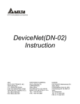
Error! Reference source not found. shows the typical circuitry for a simple USB-device
with USB4all.
• L2 and C8 build up a filter for the supply voltage. C8 should be at least 1 uF.. 10uF.
• C1 is a filter for the internal 3,3V voltage regulator of the chip.
• R2 and JP1 can be used to activate the bootloader.
• Q1, C2 und C3 generate the clock for the chip.
-7-
USB4all Manual
Figure 2 Typical circuitry for USB4all
The front-page of this document shows such a device. All usable Pins are connected to
sockets.
The next figure shows a simplified circuitry for cost sensitive applications.
Figure 3 Minimum circuitry for USB4all
The clock source can be a 20-MHz-crystal or a 20-MHz-resonator. A crystal requires load
capacitors at both terminals of the crystal. (C2 & C3) A resonator works without such
-8-
USB4all Manual
capacitors.
++ATTENTION++
If a resonator is used, then the precision of the frequency counter is limited to 0.5%.
-9-
USB4all Manual
5.2
Usable Interfaces
Die following tables shows which pins are usable for what kind of interface function. One
can see that some interfaces can not be used at the same time in parallel. Thus LCD1 can
not be used in parallel to I2C, SPI, Motor1 or Motor2. But one can use ADC (the 5 inputs
AN0..AN4), the frequency counter, RS232, I2C, LCD2, PWM1 and PWM2 in parallel.
5.2.1 Interfaces with 28-pin Control PIC
The PIC18F2455 / 2550 / 2458 / 2553 have 28 Pins.
Pin
IO-Port
ADC
FRQ
2
RA0
AN0
3
RA1
AN1
B3
4
RA2
AN2
C3
5
RA3
AN3
6
RA4
7
RA5
10
RA6
21
RB0
AN12
SDA
SDI
SDI
22
RB1
AN10
SCL
SCL
SCL
23
RB2
AN8
24
RB3
25
RB4
26
RS
232
I2C
SPI
Mwire/
SR
LCD
1
LCD
2
PWM
Motor
1..4
L297
1..4
Servo
Counter
A3
D3
FRQ
C1
AN4
(SS)
E1
A1
CL1
SB0
B1
DIR1
SB1
(CS1)
RS
RS
C2
CL2
SB2
AN9
(CS2)
R/W
R/W
D1
DIR2
SB3
AN11
(CS3)
D4
D4
A2
CL3
SB4
RB5
(CS4)
D5
D5
B2
DIR3
SB5
27
RB6
(CS5)
D6
D6
C2
CL4
SB6
28
RB7
(CS6)
D7
D7
D2
DIR4
SB7
11
RC0
12
RC1
13
RC2
17
RC6
TX
18
RC7
RX
E2
PWM2
PWM1
SDO
SDO
A4
SC0
B4
SC1
C4
SC2
D4
SC6
C3
SC7
These microcontrollers are available in 28-pin-DIL-housing (PDIP) and 28-pin SMDhousing (SOIC). The following figure shows the pinout.
- 10 -
USB4all Manual
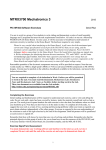
Figure 4 Pinout of the PIC18F2455 / 2550 / 2458 / 2553
5.2.2 Interfaces with 40/44-pin Control PIC
The PIC18F4455 / 4550 / 4458 / 4553 have 40 or 44 Pins.
Pin
IO-Port
ADC
FRQ
2
RA0
AN0
3
RA1
AN1
B3
4
RA2
AN2
C3
5
RA3
AN3
6
RA4
7
RA5
14
RA6
33
RB0
AN12
SDA
SDI
SDI
34
RB1
AN10
SCL
SCL
SCL
35
RB2
AN8
36
RB3
37
RB4
38
39
RS
232
I2C
SPI
Mwire/
SR
LCD
1
LCD
2
PWM
Motor
1..4
L297
1..4
Servo
Counter
A3
D3
FRQ
C1
AN4
(SS)
E1
A1
CL1
SB0
B1
DIR1
SB1
(CS1)
RS
RS
C2
CL2
SB2
AN9
(CS2)
R/W
R/W
D1
DIR2
SB3
AN11
(CS3)
D4
D4
A2
CL3
SB4
RB5
(CS4)
D5
D5
B2
DIR3
SB5
RB6
(CS5)
D6
D6
C2
CL4
SB6
40
RB7
(CS6)
D7
D7
D2
DIR4
15
RC0
E2
A4
SC0
16
RC1
PWM2
B4
SC1
PWM1
C4
SC2
17
RC2
25
RC6
TX
26
RC7
RX
19
RD0
20
RD1
21
RD2
22
RD3
27
RD4
28
RD5
29
RD6
D4
SDO
SDO
- 11 -
SB7
SC6
SC7
C3
USB4all Manual
30
RD7
8
RE0
9
RE1
10
RE2
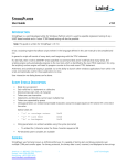
These microcontrollers are available in 40-pin-DIL-housing (PDIP) and 44-pin SMDhousing (SOIC, TQFP or QFN). The following figure shows the 40-pin-pinout.
Figure 5 Pinout of the PIC18F4455 / 4550 / 4458 / 4553
5.2.3 Output Pins
The following picture shows a simplified diagram for an output pin of the USB4all.
(for all pins, including RA4)
Figure 6 Output Pin - simplified
- 12 -
USB4all Manual
The output current for any pin should not exceed 20mA. The sum of all currents from all
output pin don’t has to exceed 200mA ( USB4all: limited to 100mA).
The output voltage level is:
Level
High at 8,5 mA Load
Low at -3,5 mA Load
general
> (Vdd-0,7V)
< 0,6V
at Vdd=5V
> 4,3V
< 0,6V
The output stage is made up from MOSFET-transistors with relatively high internal
resistivity. Because of this the output voltage depends on the load current.
Figure 7 High level at different load
At loads up to 20mA the standard TTL-level is guarantied.
- 13 -
USB4all Manual
Figure 8 Low level at different load
5.2.4 Input Pins
The most pins of Ports A (RA0..RA3, RA5, RA6) and all pins of Port B (RB0..RB7) are
normal TTL-input pins.
The pin RA4 and all pins of Port C are Schmitt-trigger-inputs (ST). The following tables list
the typical input voltages:
IO-Input
RA0..RA3, RA5, RA6, RB0..RB7
RA4, RC0..RC7
Function
TTL
ST
Input-low-Level
< 0,15 Vdd
< 0,2 Vdd
Input-high- Level
>(0.25Vdd+0.8V)
> 0,8 Vdd
Input-low- Level
< 0,75 V
<1V
Input-high- Level
> 2.05 V
>4V
At a supply voltage level of 5V this results in:
IO-Input
RA0..RA3, RA5, RA6, RB0..RB7
RA4, RC0..RC7
Function
TTL
ST
The input current of any pin will not exceed 1 uA.
All pins of Port B have internal pull-up resistors, which can be activated is needed. They
pull up the input pins to Vdd with 50 .. 400 uA. (This is an equivalent to 25 kOhm
resistors.)
++Attention++
Input voltages above Vdd or below Vss are limited by clamp diodes. The clamp
current don’t has to exceed 20mA. If such input voltages are possible, then the
clamp current has to be limited by resistors.
- 14 -
USB4all Manual
5.3
TTL-IO-Port-Pins
A detailed description of the TTL-IO-Ports is available (in Germans) at:
http://www.sprut.de/electronic/pic/grund/ioports.htm#rx
5.4
ADC-Input
The ADC can measure voltage levels between the reference values Vss (0V) and Vdd
(+5V) with 10 Bit resolution (4.88 mV) or 12 Bit resolution (1.22 mV). The resolution
depends on the type of the control PIC:
• 10 Bit: PIC18F2455/2550/4455/4550
• 12 Bit: PIC18F2458/2553/4458/4553
To guarantee a high precision the internal resistivity of the voltage source should not
exceed 2,5kOhm.
Input voltages above Vdd or below Vss are limited by clamp diodes. The clamp current
don’t has to exceed 20mA. If such input voltages are possible, then the clamp current has
to be limited by resistors. This resistor would increase the internal resistivity of the voltage
source.
By default Vss and Vdd are used as reference voltages (maximum and minimum voltage
the ADC can measure). If a smaller voltage range is required, then other reference
voltages can be used. These voltages have to be connected to special input pins. This 1..2
pins can then not be used as ADC inputs.
The upper reference voltage (upper limit for the ADC) has to be connected to AN3 (Pin 5).
The lower reference voltage (minimum voltage for the ADC) has to be connected to AN2
(Pin 4). Both reference voltages have to be in the range between Vdd and Vss. The
difference between both reference voltages should not be smaller then 2 V.
5.5
Frequency Counter Input
The frequency counter (FRQ, Pin 6) can measure frequencies up to 50 MHz. the input pin
has a Schmitt-trigger (ST). The high part of the input signal has to be higher then 4V (0.8 x
Vdd) and the low part has to be below 1 V (0.2 x Vdd).
Input voltages above Vdd or below Vss are limited by clamp diodes. The clamp current
doesn’t has to exceed 20mA. If such input voltages are possible, then the clamp current
has to be limited by a resistor.
5.6
RS232-Interface
The RS232-interface-pins of the USB4all-chip transmit and receive signals at TTL-voltage
level. They have to be converted to regular RS232-values by a regular RS232-driver
circuit. (e.g. MAX232).
(+5V->-12V: 0V->+12V).
- 15 -
USB4all Manual
Figure 9 RS232-Interface with external driver
Additional information is available (in German) at:
http://www.sprut.de/electronic/interfaces/rs232/rs232.htm
http://www.sprut.de/electronic/pic/grund/rs232.htm
For short RS232-connections such an external driver may not be necessary. In this case
only a current limiting resistor inside the RX-line is needed to connect the USB4all with a
regular RS232-port. In this case the signal levels do not meet the official RS233specifications, but the most modern PC-mainboards will accept these signals.
Figure 10 RS232-Interface without external driver
During the initiation of the RS232-interface the interface version (with or without external
driver) has to be specified.
- 16 -
USB4all Manual
5.7
I2C- Interface
USB4all can act as Master for one I2C-bus. Both wires of the bus (SDA and SDC) need
external pull-up-resistors of 1,8 Kilo-Ohm.
Additional information is available (in German) at:
http://www.sprut.de/electronic/pic/grund/i2c.htm
Figure 11 I2C-Interface
5.8
Dot-Matrix LCD-Interface
USB4all can control up to 2 HD44780-compatible LCD-dot-matrix-displays.
Each display can have up to 2x40 or 4x20 positions for symbols.
Alternative a single display with up to 4x40 symbols can be controlled.
The display-pins can be directly connected to the pins of USB4all. The pins D0..D3 of the
display are not needed.
The pins Vdd (+5V) und Vss (0V) of the display have to be connected to Vdd and Vss of
the USB4all.
The pin Vo has to be connected to a (display type specific) contrast voltage. For the most
display types (normal temperature displays) this voltage is in the range of 0V … 1V.
- 17 -
USB4all Manual
Figure 12 Dot-Matrix-LCD Interface
The figure shows the typical connection between one display and USB4all. A second
display would be connected in parallel to the first display with the exception of the “E”-pin.
The E-pin of the second display would be connected to pin RC0 of USB4qall.
Additional information is available (in German) at:
http://www.sprut.de/electronic/lcd/index.htm
5.9
PWM-Output
There are 2 PWM-output (pulse width modulated square wave) pins. Both pins generate
signals of the same frequency, but the can have different duty cycle.
5.10
5.10.1
Stepper Motor Output
Stepper-Motor-Interface with ABCD-Phase-outputs
This interface can be used for low-power unipolarer stepper motors.
Every channel has 4 output-pins. They have to be driven to reach the necessary current
for the motor. The driver can be made from single transistors or from special integrated
circuitries (e.g. den ULN2075B or L298).
The following figure shows an example circuit with bipolar transistors.
Figure 13 simple Stepper Motor Interface
5.10.2
Stepper Motor Interface with L297
The integrated circuit L297 together with the L298 is a popular solution to drive stepper
motors. USB4all can control up to 4 channels with these chips.
- 18 -
USB4all Manual
The two output pins of each USB4all-channel have to be connected to the pins “clock”
(CLK) and “direction” (CW/CCW) of the L297. The “enable”-pin of the L297 has to be
connected to High-level. The “half/full”-pin of the L297 has to be connected with the
correct level for the required mode.
5.11
Model-Servo-Output
There are up to 13 outputs to drive standard model servos. The output signals are positive
pulses (TTL level). These can be directly fed into a model servos input pin.
Figure 14 Model-Servo
- 19 -
USB4all Manual
6 Software
6.1
USB-Device
The heart piece of USB4all is the USB4all-firmware. It would be possible to burn it directly
into the PIC18F2455 (by a programmer) but I don’t suggest this.
It is much smarter to burn only the bootloader into the PIC18F2455. After this was done,
you can use this bootloader to load the latest firmware into the chip.
If the USB4all is connected to the PC, then under normal condition the firmware is
launched. But is the bootloader is required (e.g. to load a new version of the firmware), it
can be activated by an electric connection between pin1 and Vss. In may layouts exists a
jumper for this porpoise. The jumper has to be closed before the device is connected to
the PC.
The software USBoot (which is necessary to use the bootloader) can activate the
bootloader of USB4all-MCD (but not of USB4all-CDC) even without this jumper.
6.2
PC
The USB4all comes in two flavors:
USB4all-CDC
This version can be controlled via a virtual RS232-interface (e.g. COM3 or COM4). On
windows-systems it needs the USB RS-232 Emulation Driver. The use of the virtual
COM-port allows the use of simple terminal programs or other simple means to control this
device.
USB4all-MCD
This version needs the Microchip Custom Driver. The device can be controlled by
functions that are contained inside a special DLL.
6.2.1 Driver Installation
The drivers have to be installed before the device is connected to the PC.
The USB4all-MCD needs the Microchip Custom Driver (mpusbapi.dll). The driver is
aviable from the Microchip homepage but is contained in my USB4all-ZIP-file too.
The same driver is needed by my programmer Brenner8/9 and the bootloader.
By the way: you should not connect Brenner8/9 and USB4all-MCD to the same PC in
parallel. The USB4all-test-software might be confused.
The USB4all-CDC needs the USB RS-232 Emulation Driver. This driver is part of
Windows. Vou will have to use the inf-file from the ZIP-file to install this driver.
The bootloader of USB4all (Bootloader-5) needs the Microchip Custom Driver.
Consequently users of USB4all-CDC have to install both drivers.
6.2.2 Installation: Microchip Custom Driver
Detailed description of driver installation is contained in the German version of this
document only.
- 20 -
USB4all Manual
6.2.3 Installation: USB RS-232 Emulation Driver
Detailed description of driver installation is contained in the German version of this
document only.
If the USB4all is connected to the PC after driver installation, the USB4all-CDC should be
detected as additional COM-port (device manager)
Figure 15 USB4all-CDC as emulated COM3-Port
- 21 -
USB4all Manual
7 List of Commands
The USB4all is controlled by commands. Every command is a short string of bytes. The
string is send via USB to the USB4all, the device works off this command and sends back
a report. This report is a string of 16 bytes.
The length of the command string can not exceed 64 bytes. However, the most commands
need only 2 … 4 bytes.
For the USB4all-CDC the bytes of the command string have to be converted into an
ASCII-string. This text-string is 3 times longer then the byte string. This text string doesn’t
has to exceed a length of 64 bytes! This limits the number of command-bytes for the
USB4all-CDC to 20 only (instead of 64 for the USB4all-MCD).
The first byte is addressing the subsystem of USB4all, which will receive and work off the
command (e.g. RS232 or ADC). The following subsystems exist:
•
•
•
•
•
•
•
•
•
•
•
•
•
•
•
•
•
•
•
•
•
•
•
•
•
•
•
0x50
0x51
0x52
0x53
0x54
0x55
0x56
0x57
0x58
0x59
0x5A
0x5B
0x5C
0x5D
0x5E
0x5F
0x60
0x61
0x62
0x63
0x64
0x65
0x66
0x67
0x68
0x69
0xFF
TTL-IO-Pins
10-Bit-ADC
frequency counter
SPI-Interface
I2C-Interface
Dot-matrix-LCD-Display Nr. 1
Dot-matrix-LCD-Display Nr. 2
PWM-output 1
PWM-output 2
RS232-Interface
internal EEPROM
key-matrix
stepper-motor Nr. 4
stepper-motor Nr. 1
stepper-motor Nr. 2
stepper-motor Nr. 3
L297 stepper-motor Nr. 1
L297 stepper-motor Nr. 2
L297 stepper-motor Nr. 3
L297 stepper-motor Nr. 4
model-servo-channel B
model-servo-channel C
Shift register
Micro wire
Counter 0
Counter 3
Reset
The second byte contains the command. For the most subsystems this byte has the
following meaning:
- 22 -
USB4all Manual
•
•
•
•
•
•
0x00
0x01
0x02
0x03
0x04
0x05
deactivate the subsystems
initiate the subsystems
send one byte
read one byte
send a string of bytes
receive a string of bytes
If additional data is needed, then it will follow starting with the 3d byte.
- 23 -
USB4all Manual
7.1
TTL-IO-Pins
Electrical specification
USB4all has 20 or 31 digital IO-pins. Each can be used as output or as input for digital
(TTL) signal levels. If a pin is switched into the output-mode, then it can deliver up to 25
mA. The sum of all output currents don’t has to exceed 200 mA.
(Because of USB-limitations the maximum current should not exceed 100 mA).
All input-pins have clamp diodes to Vss (ground) and Vdd (+5V). If input voltage level can
be above Vdd or below Vss, then a serial resistor has to be used inside the input line to
limit the clamp-current to not more then 20 mA.
An input voltage of +12V requires an input-serial-resistor of at least 350 Ohms.
After power-up all pins are configured as digital input-pins.
The primary 20 IO-pins are available in all USB4all-Versions They are organized in 3
ports:
• PortA contains 7 pins: RA0..RA6
• PortB contains 8 pins: RB0..RB7
• PortC contains 5 pins: RC0..RC2 and RC6..RC7
If any other subsystem needs pins, then it will borrow these pins if the subsystem is
initiated. If later this subsystem is switched off, then it will give these pins back top the
TTL-IO-pin subsystem.
There are 8 different commands for IO-pins:
Byte0
Subsystem
0x50
IO-Pins
Byte1
Command
0x00
off
switch off all OutputPins
0x01
initiate
0x02
write to all ports
0x03
read from all Ports
0x04
Switch selected pins to
Input
0x05
Switch selected pins to
Output
0x06
Set selected pins to 5V
0x07
Set selected pins to 0V
Byte 2
Byte 3
Byte 4
Byte 5
-
-
-
-
In/out-mask for
PortA
In/out- mask for
PortB
In/out- mask for
PortC
Value for PortA
Value for PortB
Value for PortC
Pull-up for
PortB:
0: off
1: on
-
-
-
-
-
In- mask for
PortA
In- mask for
PortB
In- mask for
PortC
-
Out- mask for
PortA
Out- mask for
PortB
Out- mask for
PortC
-
High- mask for
PortA
Low- mask for
PortA
High- mask for
PortB
Low- mask for
PortB
High- mask for
PortC
Low- mask for
PortC
-
USB4all will answer with a 16 byte long reply. Only for command 3 this reply contains
usable data:
- 24 -
USB4all Manual
Byte 0
0x50
Byte 1
0x03
Byte 2
Value from
PortA
Byte 3
Value from
PortB
Byte 4
Value from
PortC
Byte 5
-
The 20 TTL-IO-pins of the 3 ports are controlled by 3 bytes (MaskA, MaskB, MaskC).
Every IO-pin is represented by exactly one bit in one of the 3 masks.
Mask
MaskA
MaskB
MaskC
Bit 7
RB7
RC7
Bit 6
RA6
RB6
-
Bit 5
RA5
RB5
-
Bit 4
RA4
RB4
RC4
Bit 3
RA3
RB3
-
Bit 2
RA2
RB2
RC2
Bit 1
RA1
RB1
RC2
Bit 0
RA0
RB0
RC0
0x03-Read from all ports
Command 0x03 reads the values of all IO-pins and reports this values in 3 bytes (the
masks) to the PC. A low level at a pin is represented by a 0 inside the mask and a high
level by a 1.
0x01-inititiate
Generally the TTL-IO-pin-subsystem is operational even without any initializing. After
power-up the command 0x03 can be used to red the levels at all IO-pins. But all pins are
configured as input-pins by default. One can read the voltage level applied from the
outside to this pin, but one can not put out any signal (e.g. to control a LED).
Before a pin can put out a voltage, it has to be configured as output-pin by the command
0x01.
This command contains 3 masks (byte 2...4). Inside these masks for every pin exists a
single bit. If this bit is “0” then the related pin will be set to “output”. In the bit is “1” then the
pin becomes an “input”-pin.
After the 3 masks follows the byte 5. If this byte has the value 1 then all internal pull-ups of
PortB will be activated.
The string (0x50-0x01-0x00-0x00-0x00-0x00) sets all pins to “output”.
The string (0x50-0x01-0xFF-0xFF-0xFF-0x00) seta all pins back to “input” again.
0x04-switch selected pins to Input
0x05- switch selected pins to Output
The command 0x01 will always influence all pins.
If one likes to switch only some pins to output or to input (without a change to the function
off all other pins), then the commands 0x04 and 0x05 may be the better choice.
These commands contain 3 masks for the 3 ports, but there function is different then in
command 0x01. A bit with the value”0” means, that the related pin will not be modified. But
all pins with a “1” in the related mask-bit will be switched to input (command 0x04) or
output (command 0x05).
The string (0x50-0x04-0x01-0x80-0x00) switches the pins RA0 & RB7 to input.
The string (0x50-0x05-0x01-0x00-0x00) switches the pins RA0 to output.
- 25 -
USB4all Manual
0x02-Write to all ports
With this command one can change the output value of all output pins from all 3 ports.
The command contains 3 masks. A “0”-bit in the masks stands for a low-output-level (0V)
and a “1” for a high output level (5V).
Input-pins will of course not react. But they will store the value for later use. If any input pin
will later be switched to output-state, then it will immediately drive the output voltage value
from this command.
0x06-set selected pins to +5V
0x07- set selected pins to 0V
The command 0x02 will always change the output value of all output-pins.
If the values of only some output pins have to be changed, then the commands 0x06 and
0x07 can be used.
These commands contain 3 masks for the 3 ports, but there function is different then in
command 0x02. A bit with the value”0” means, that the output value of this pin will not be
changed. But all output-pins with a “1” in the related mask-bit will be switched to High
(command 0x06) or to Low (command 0x07).
The string (0x50-0x06-0x01-0x80-0x00) will switch the pins RA0 & RB7 to High.
The string (0x50-0x07-0x01-0x00-0x00) will switch the pin RA0 back to Low.
7.1.1 40/44 pin version
The special 40-pin-firmware for USB4all supports 11 additional IO-pins. They are
organized in the Ports D and E.
The additional IO-pins are:
• PortD contains 8 pins: RD0..RD7
• PortE contains 3 pins: RE0..RE2
These pins are controlled via 2 additional masks (MaskD & MaskE).
Mask
MaskA
MaskB
MaskC
MaskD
MaskE
Bit 7
RB7
RC7
RD7
-
Bit 6
RA6
RB6
RD6
-
Bit 5
RA5
RB5
RD5
-
Bit 4
RA4
RB4
RC4
RD4
-
Bit 3
RA3
RB3
RD3
-
Bit 2
RA2
RB2
RC2
RD2
RE2
Bit 1
RA1
RB1
RC2
RD1
RE2
Bit 0
RA0
RB0
RC0
RD0
RE0
To initiate all 5 ports the user has to use the command 0x11 (instead of command 0x01).
On 28-pin devices the commands 0x01 and 0x11 are identical. But on 40-pin devices the
command 0x11 contains the IO-masks for the additional pins in byte 5 and byte 6 and the
pull up-command is located in byte 7.
The commands 0x02 up to 0x07 contain the necessary information for the both additional
port in the bytes 0x05 and 0x06.
There are 9 different commands for IO-pins on 40-pin devices:
- 26 -
USB4all Manual
Byte0
Subsy
stem
0x50
IOPins
Byte1
Command
Byte 2
Byte 3
Byte 4
Byte 5
Byte 6
Byte 7
0x00
off
switch off
all OutputPins
0x01
initiate
-
-
-
-
-
-
In/out-mask
for PortA
In/out- mask
for PortB
In/out- mask
for PortC
0x11
initiate
In/out-mask
for PortA
In/out- mask
for PortB
In/out- mask
for PortC
Pull-up for
PortB:
0: off
1: on
In/out- mask
for PortD
In/out- mask
for PortE
0x02
write to all
ports
0x03
read from
all Ports
0x04
Switch
selected
pins to
Input
0x05
Switch
selected
pins to
Output
0x06
Set
selected
pins to 5V
0x07
Set
selected
pins to 0V
Value for
PortA
Value for
PortB
Value for
PortC
Value for
PortD
Value for
PortE
Pull-up for
PortB:
0: off
1: on
-
-
-
-
-
-
-
In- mask for
PortA
In- mask for
PortB
In- mask for
PortC
In- mask for
PortD
In- mask for
PortE
-
Out- mask
for PortA
Out- mask
for PortB
Out- mask
for PortC
Out- mask
for PortD
Out- mask
for PortE
-
High- mask
for PortA
High- mask
for PortB
High- mask
for PortC
High- mask
for PortD
High- mask
for PortE
-
Low- mask
for PortA
Low- mask
for PortB
Low- mask
for PortC
Low- mask
for PortD
Low- mask
for PortE
-
USB4all will answer with a 16 byte long reply. Only for command 3 this reply contains
usable data:
Byte 0
0x50
Byte 1
0x03
Byte 2
Value from
PortA
Byte 3
Value from
PortB
- 27 -
Byte 4
Value from
PortC
Byte 5
Value from
PortD
Byte 6
Value from
PortE
USB4all Manual
7.2
10-Bit / 12-Bit-ADC
USB4all contains an ADC with 10 selectable analog inputs. It can measure voltage levels
from 0V to 5V with 10 bit (4.88 mV) or 12 bit (1.22 mV) resolution. The resolution depends
on the type of the control PIC:
• 10 Bit: PIC18F2455/2550/4455/4550
• 12 Bit: PIC18F2458/2553/4458/4553
The following list shows the names of the analog inputs and their pins:
• AN0 = RA0
• AN1 = RA1
• AN2 = RA2
• AN3 = RA3
• AN4 = RA5 (!)
• AN8 = RB2
• AN9 = RB3
• AN10 = RB1
• AN11 = RB4
• AN12 = RB0
After power-up all pins are digital inputs. To use the ADC, it has to be initiated by the
command 0x01. With this command the user decides, how many digital IO-pins should be
converted into analog input pins for the ADC.
As long they are analog pins, they are not part of the digital IO-pins-subsystem. If the ADC
will be switched off by the command 0x00, then the analog pins are converted back into
digital pins, and handed over to the digital-IO-pin-subsystem.
Four different commands are available to control the ADC.
Byte 0
Subsystem
0x51
10-Bit-ADC
Byte1
Command
0x00
Switch ADC off,
al ADC-pins become
digital pins
0x01
Initiate ADC
0x02
Select one ADC-input for
the following
measurements
- 28 -
Byte 2
Byte 3
-
-
Number of analog ADCinputs (0..10)
0: no input (nonsense)
1: AN0
2: AN0..AN1
3: AN0..AN2
4: AN0..AN3
5: AN0..AN4
6: AN0..AN4,AN8
7: AN0..AN4,AN8..9
8: AN0..AN4, AN8..10
9: AN0..AN4, AN8..11
10: AN0..AN4, AN8..12
0: AN0
1: AN1
2: AN2
3: AN3
4: AN4
5: AN8
6: AN9
Reference voltages:
0: Vss=Vref-/Vdd=Vref+
1: Vss=Vref-/AN3=Vref+
2: AN2=Vref-/Vdd=Vref+
3: AN2=Vref-/AN3=Vref+
-
USB4all Manual
0x03
Measure the voltage
7: AN10
8: AN11
9: AN12
-
-
USB4all returns 16 bytes to the PC. Only after command 0x03 these bytes contain data:
Byte 0
0x51
Byte 1
0x03
Byte 2
Low
Byte 3
High
The ADC-result is 10 or 12-bit wide. Byte 2 (Low) contains the lower 8 bit while byte 3
(High) contains the upper bits (2 or 4) of the result.
Reference Voltages
The ADC measures the input voltage in reference to a minimum reference voltage (Vref-)
and a maximum reference voltage (Vref+). If an input voltage is equal to Vref-, then it will
be converted into the value 0. If the voltage is equal to Vref+, then it will be converted into
1023.
To keep it simple one can use Vss as Vref- and Vdd as Vref+. In this case the ADC will
measure voltages from 0V up to 5V with 4.88 mV resolution (5V/1024) or 1.22 mV
resolution (5V/4096). The ADC will use Vss and Vdd as reference voltages, if the 3d byte
of the command 0x01 is equal to 0.
The string (0x51 - 0x01 - 0x01 - 0x00) initiates the ADC and selects AN0 as input.
The string (0x51 - 0x02 - 0x00) selects AN0 as input.
The string (0x51 - 0x03) measures the voltage at AN0.
A possible reply of USB4all with 1-/bit-ADC may be (0x51 - 0x03 - 0x12 - 0x03 - ..).
The result of the measurement is the hexadecimal number 0x0312. This is 786 in the
decimal system. Because Vss (0V) and Vdd (5V) are used as reference voltages, this
result is equal to
5V / 1023 * 786 = 3,84V.
The supply voltage (Vdd) of digital circuitries is normally not stable enough to use the 10bits of resolution of this ADC. For good precision a stable and accurate reference voltage
is needed. Stable external reference voltages can be connected to the pins AN2 and AN3
to the USB4all. Of course these pins can then not be used as normal analog inputs for the
ADC.
Byte 3 of the command 0x01 controls the use ox external or internal reference voltages.
External reference voltages don’t have to be above Vdd or below Vss. The difference
between both reference voltage levels should be at least 2 V to use the full resolution of
the ADC.
It is often a good compromise to use internal Vss as Vref- and to connect only a external
Vref+ (von 2,5 .. 5V via AN3) to the ADC. In this case AN2 can be used as normal analog
input for the ADC.
+NOTICE+
If the user wants to change the number of analog inputs of a running ADC, then the ADC
should first switched off (command 0x00) before it will be re-initiated with the new number
of input channels (command 0x01).
- 29 -
USB4all Manual
7.3
Frequency Counter
USB4all has one input to measure frequencies. It can measure signals from 150 kHz up to
50 MHz with 5 decimals resolution (error < 0.013%). At lower frequencies the error don’t
exceeds 10 Hz... 20 Hz.
The frequency counter has a Schmitt trigger input. The high-part of the input signal has to
be above 4 V and the low part below 1 V.
FRQ-input is using a pin of PortA:
• FRQ = RA4
The frequency counter doesn’t needs to be initiated. At the begin of the measurement the
pin RA4 is switched to input state. After the measurement it stays in this state.
There are 2 possible commands for the frequency counter:
• Command 0x05 (autorange mode) selects the ideal prescaler and measures the
frequency with best precision (100ms period). The result is the frequency in Hertz as
32-bit value.
• Command 0x03 (manual mode) is less convenient. Here the user has to choose the
prescaler ratio and the counting period. The result is the raw counting result (16-bit).
The user has to calculate the signal frequency by himself.
++ATTENTION++
The counter interrupts all other processes of USB4all for up to 100 ms. That means, that
the RS232-port will not receive data, the stepper motors will stop … during this time.
Byte 0
Subsystem
0x52
FRQ
Byte1
Command
0x03
Frequency measurement
manual
0x52
FRQ
0x05
Frequency measurement
autorange
Byte 2
Byte 3
Internal prescaler:
8: 1:1
0: 2:1
1: 4:1
2: 8:1
3: 16:1
4: 32:1
5: 64:1
6: 128:1
7: 256:1
-
Period (time to count):
0: 10ms
1: 1ms
2: 10ms
3: 100ms
-
USB4all replies 16 byte. After command 0x03 the reply contains the counting result, after
command 0x05 it contains the frequency:
Byte 0
0x52 : ok
0xFF: out of range
0x52 : ok
0xFF: out of range
Byte 1
0x03
Byte 2
Low
Byte 3
High
Byte 4
-
Byte 5
-
0x05
0. Byte
(Low-Bye)
1. Byte
2. Byte
3. Byte
(High-Byte)
The counting result (command 0x03) is a 16-bit value. Low (byte 2) contains the lower 8 bit
and High (byte 3) contains the upper 8 bit.
The frequency (command 0x05) is a 32-bit value (byte 2.. byte 5).
- 30 -
USB4all Manual
The use of the aurorange mode (0x52-0x05) is:
The string (0x52 - 0x05) starts the measurement.
A possible answer is the string (0x52 - 0x05 - 0x40 - 0x78 - 0x7D - 0x01 - ...).
The result is the hexadecimal number 0x017D7840. This is converted into decimal
25000000. The frequency counter has measured 25 MHz.
The use of the manual mode (0x52-0x03) is much more difficult. I don’t suggest using it.
However, if one likes to use the manual mode, then he should red the details described in
the German version of this handbook.
- 31 -
USB4all Manual
7.4
RS-232
The USB4all contains an RS232-port for asynchronous serial communication with speed
from 9600 baud up to 115200 baud. It transfers always 8 bits without parity.
The RS232 is using 2 pins of the PortC:
•
TX = RC6
•
RX = RC7
The pins should be driven by normal RS232 driver circuits (e.g. MAX232) to guarantee
correct signal level and polarity. However, for short RS232-connections it is possible to
omit the external driver.
After power-up these pins are digital inputs. Command 0x01 initiates the RS232-interface
and converts these pins into RS232-pins.
After the RS233 subsystem is switched off (command 0x00) the pins are again part of the
digital-IO-subsystem
The RS232-subsystem supports the following 8 commands:
Byte 0
Subsystem
0x59
RS232
Byte 1
Command
0x00
off
0x01
initiate
0x02
transmit one byte
0x03
Receive one byte
0x04
Transmit a string
0x05
Receive a string
0x06
Read number of byte in
buffer
0x07
Erase buffer
Byte 2
Byte 3
Byte 4
Byte 5
-
-
-
-
Bit3..0: baud rate
- 0: 19200 Baud
- 1: 115200 Baud
- 2: 57600 Baud
- 3: 19200 Baud
- 4: 9600 Baud
Bit7 (no) driver
- external driver
- no external driver
Symbol/byte
-
-
-
-
-
-
-
-
-
-
Length of String
1. symbol/byte
2. symbol/byte
.....
Length of String
-
-
-
-
-
-
-
-
-
-
-
The length for a transmit string (command 0x04) is limited to 61 bytes (for USB4all-MCD)
or 20 bytes (USB4all-CDC).
The length for a receive string (command 0x05) is limited to 13 bytes.
USB4all sends 16 bytes back to the PC. Only after commands 0x03, 0x05 and 0x06 these
bytes contain data:
Byte 0
Byte 1
Byte 2
Byte 3
- 32 -
Byte 4
Byte 5
USB4all Manual
0x00 or
0xFF
0x59
0x59
command
0x03
Received byte
-
-
-
0x05
0x06
Length of received string
Length of string in buffer
1. symbol/byte
-
2. symbol/byte
-
.....
-
USB4all has a 32 byte (USB4all-MCD) or 20 byte (USB4all-CDC) large internal receive
buffer. After the RS232 interface was initiated (command 0x01) all via RS232 received
signals are written into this buffer.
The commands 0x03 and 0x05 read data from this buffer.
If the buffer is full with data, then USB4all will ignore any additional data from the RS232
interface until the buffer (or a part of it) was emptied by command 0x03, 0x05 or 0x07.
Command 0x03 reads only one byte from the buffer and sets byte 0 to the value 0x00
(received successfully). If the buffer was empty, then byte 0 is set to 0xFF (nothing
received).
Command 0x05 tries to read the requested number of bytes from the buffer. If the number
of bytes inside the buffer is smaller, then the available bytes are read. In byte 2 then
number of bytes is reported back to the PC.
Command 0x06 reports the number of bytes that are contains in the receive buffer.
Command 0x07 erases the buffer.
Command 0x01 - initiate
The RS232-interface supports only the 8-bit mode without parity or flow control. This is the
most popular mode anyway. Fife different baud rates are available. The baud rate is
selected by the 4 lower bits of the byte 2.
The bit 7 of byte 2 can be set to invert the RS232-signals. If an external driver (e.g.
MAX232) is used, then this bit has to be set to 0. But if no external driver is used and the
pins of the USB4all-Chip are (via current limiting resistor) directly connected to an RS232port, then this bit has to be set to 1.
- 33 -
USB4all Manual
7.5
I2C-Interface
USB4all contains one I2C-interface. It can operate in master-mode (but not as slave).
It is not possible to use the I2C-interface in parallel with the SPI-interface, the shiftregister-interface or the microwire-interface.
The I2C-interface is using the following 2 pins of PortB:
• SDA = RB0
• SDC = RB1
After power-up these pins are digital inputs. Command 0x01 initiates the I2C-interface and
converts these pins into I2C -pins.
After the I2C subsystem is switched off (command 0x00) the pins are again part of the
digital-IO-subsystem
The I2C -subsystem supports the following 6 commands:
Subsystem
0x54
I2C
Command
0x00
off
0x01
initiate
0x02
Write one byte
0x03
Read one byte
0x04
Write a string
0x05
Read a string
0x12
Write one byte
0x13
Read one byte
0x14
Write a string
0x15
Read a string
Byte 2
Byte 3
0: Master
0: 100 kHz
1: 400 kHz
2: 1 MHz
Databyte
address
(7 Bit)
address
(7 Bit)
address
(7 Bit)
address
(7 Bit)
addressH
(upper 2 Bit)
addressH
(upper 2 Bit)
addressH
(upper 2 Bit)
addressH
(upper 2 Bit)
Number of
bytes
Number of
bytes
addressL
(lower 8 Bit)
addressL
(lower 8 Bit)
addressL
(lower 8 Bit)
addressL
(lower 8 Bit)
Byte 4
Byte 5
Byte 6
1.
Databyte
-
...
...
-
-
1. Databyte
...
Databyte
Number
of bytes
Number
of bytes
The length for a transmit string (command 0x04, 0x14) is limited to 60 bytes.
The length for a receive string (command 0x05, 0x15) is limited to 12 bytes.
USB4all sends 16 bytes back to the PC. Only after commands 0x03, 0x05, 0x13 and 0x15
these bytes contain data, which was read from the I2C-slave(s).
Byte 0
0x00 or
error code
Byte 1
0x03
0x05
0x13
0x15
Byte 2
Received
byte
address
Received
byte
addressH
Byte 3
Byte 4
Byte 5
Byte 6
Number of
bytes
1. Databyte
...
....
addressL
Number of
bytes
1. Databyte
....
- 34 -
USB4all Manual
The commands 0x02 ... 0x15 will access to the I2C bus to read or write data. If this was
successful, then the byte 0 of the response string will be set to 0. If not, then this byte will
contain an error code:
• 0x00 - no error
• 0xFF - bus-collision during read access
• 0xFE - „bus device responded with NOT ACK“ during write access
• 0xFD - „return with write collision error” during write access
Notice for 7-Bit-Address
The commands from 0x02 up to 0x05 are for communication with 7-bit address-slaves.
The 7-bit address is really really really only 7 bit long. USB4all will add a 0 or 1 to the end
of the address to convert this into an 8-bit-write ore read-address.
But the user has to send to USB4all only the 7 bit long core address without the additional
1 or 0.
The MSB of byte 2 is zero. (“0xxxxxxx”)
Notice for 10-Bit-Address
The commands from 0x12 up to 0x15 are for communication with 10-bit address-slaves.
A 10-bit address doesn’t fits into a single byte. Consequently the 10-bit address is spitted
into to parts. Byte 2 contains the upper 2 bits. The 6 upper bits of this byte are set to zero.
(“000000xx”)
The lower 8 bits of the address are contained in byte 3.
- 35 -
USB4all Manual
7.6
SPI-Interface
USB4all contains one SPI-interface.
It is not possible to use the SPI-interface in parallel with the I2C-interface, the shiftregister-interface, the microwire-interface or the RS232-interface.
The SPI-interface is using the following 2 pins:
• SDO = RC7
• SDI = RB0
• SCK = RB1
• SS = RA5 (in Slave-Mode with Slave-Select only)
• CS = RB2... RB7 (optional in Master-Mode)
After power-up these pins are digital inputs. Command 0x01 initiates the SPI -interface
and converts these pins into SPI -pins.
After the SPI subsystem is switched off (command 0x00) the pins are again part of the
digital-IO-subsystem
The SPI -subsystem supports the following 4 commands:
Subsystem
0x53
SPI
Command
0x00
off
0x01
initiate
0x02
Transmit 1
bytes
0x03
receive one
byte
0x04
Transmit
multiple bytes
Byte 2
-
Byte 3
-
Byte 4
-
Byte 5
-
Number of
slaves
Chip select
Clock
Mode
Sample
Databyte
-
-
Chip select
-
-
-
Chip select
Number of
databytes
1. Databyte
2. Databyte
USB4all sends 16 bytes back to the PC. Only after commands 0x02 and 0x03 these bytes
contain data, which was read from the SPI-slave(s).
Byte 0
0x53
Byte 1
0x02
Byte 2
Chip select
0x53
0x03
Chip select
Byte 3
0 - ok
255- error
Received byte
Byte 4
-
Deactivate (0x00)
This command switches off the SPI-subsystem. The SPI-pins are handed over to the IOPin-subsystem.
Initiate (0x01)
This command initiates the SPI-interface. It selects clock-frequency, clock-polarity and
clock-idle-level. These settings are based on data in the bytes 2 … 5.
As an SPI-master the USB4all can control up to 6 chip select (CS) lines to control up to 6
slaves via the same SPI-bus. The number of required CS-lines is in byte 2. The CS-lines
- 36 -
USB4all Manual
are borrowed from the IO-Pin-subsystem.
After the SPI-subsystem is switches off (command 0x00) these lines will become part of
the IO-Pin-subsystem again.
Byte 2
0
1
2
3
4
5
6
CS1
RB2
RB2
RB2
RB2
RB2
RB2
CS2
RB3
RB3
RB3
RB3
RB3
CS3
RB4
RB4
RB4
RB4
CS4
RB5
RB5
RB5
CS5
RB6
RB6
CS6
RB7
The interface can operate with one of 4 bus-master-mode-clock-frequencies and in one of
2 Slave-Modes. The modes are controlled by data in byte 3.
Byte3
0
1
2
3
4
5
6
Mode
Default (Master)
Master
Master
Master
Reserved - do not use!
Slave with Slave-Select (Pin 7)
Slave without Slave-Select
Clock-frequencies
Default (750 kHz)
12 MHz
3 MHz
750 kHz
Reserved - do not use!
from master
From master
The interface can operate in one of 4 different transmit modes:
Byte 4
0
1
2
3
4
Transmit at the …
Default (rising edge)
rising edge
falling edge
falling edge
rising edge
Clock idle levelDefault (low)
low
high
low
high
The interface can read the voltage level of the SDI-pin at one of to possible point in time:
Byte 5
0
1
2
Read the data …
Default (at the end of data-out-time)
In the middle of data-out-time
In the middle of data-out-time
Transmit one byte (0x02)
This command will send the byte 3 via SPI-interface. If byte 2 contains an existing slave
number, then the CS line for this slave will be activated. If bit 6 of byte2 is set, then the
CS-line will not be deactivated at the end of the data transfer.
Byte 2
Meaning
Bit 7
-
Bit 6
0: finally CS switch off CS
1: don’t switch off CS
Bit 5
-
Bit 4
-
Bit 3 Bit 2 Bit 1
Number of the slave
(0 .. 6)
Bit0
The byte 3 of the reply is by default set to 0. If a bus collision happened during
transmission, then this byte will be set to 255.
Receive one byte (0x03)
- 37 -
USB4all Manual
This command will read one byte from the SPI-interface. If byte 2 contains an existing
slave number, then the CS line for this slave will be activated. If bit 6 of byte2 is set, then
the CS-line will not be deactivated at the end of the data transfer.
Byte 2
Meaning
Bit 7
-
Bit 6
0: finally CS switch off CS
1: don’t switch off CS
Bit 5
-
Bit 4
-
Bit 3 Bit 2 Bit 1
Number of the slave
(0 .. 6)
Bit 0
Transmit multiple bytes (0x04)
This command can send multiple databytes via SPI. Byte 3 contains the number of
databytes to. The byte 4 is the first databyte.
With a single command can be send up to 60 databytes (USB4all-MCD) or 16 databytes
(USB4all-CDC).
If byte 2 contains an existing slave number, then the CS line for this slave will be activated.
If bit 6 of byte2 is set, then the CS-line will not be deactivated at the end of the data
transfer
If bit 7 of byte2 is set, then the CS-line will be deactivated between the individual
databytes.
Byte 2
Meaning
Bit 7
0: CS for the
whole block
1: CS for every
byte
Bit 6
0: finally CS switch off CS
1: don’t switch off CS
Bit 5
-
Bit 4
-
Bit 3 Bit 2 Bit 1 Bit0
Number of the slave
(0 .. 6)
If more then 60 databytes (USB4all-MCD) or 16 databytes (USB4all-CDC) have to be
transferred, then the command 0x04 can be used multiple times in a sequence. For every
transfer (except the last one) the bit 2 of byte 6 should be set to 1. Thus the CS-line is kept
active between the transfers. For the last call of command 0x04 this bit should not be set.
This will deactivate the CS-line after the last transfer.
- 38 -
USB4all Manual
7.7
Microwire (jet not tested)
USB4all contains one microwire-interface.
It is not possible to use the microwire -interface in parallel with the I2C-interface, the shiftregister-interface, the SPI-interface or the RS232-interface.
The microwire-interface is using the following pins:
• SDO = RC7
• SDI = RB0
• SCK = RB1
• SS = RA5
After power-up these pins are digital inputs. Command 0x01 initiates the microwireinterface and converts these pins into microwire-pins.
After the microwire subsystem is switched off (command 0x00) the pins are again part of
the digital-IO-subsystem
The microwire -subsystem supports the following 4 commands:
Subsystem
0x67
Microwire
Command
0x00
off
0x01
initiate
0x02
Transmit one byte
0x03
Receive one byte
Byte 2
-
Byte 3
-
Byte 4
-
0: 750 kHz
1: 12 MHz
2: 3 MHz
3: 750 kHz
databyte
-
-
0-do not wait
1- wait until ready
high
-
low
-
USB4all sends 16 bytes back to the PC. Only after command 0x03 these bytes contain
data, which was read from the microwire bus.
Byte 0
0x67
Byte 1
0x03
Byte 2
Received databyte
- 39 -
Byte 3
-
Byte 4
-
USB4all Manual
7.8
Shift-Register Interface
The USB4all can control external shift-registers.
It is not possible to use the shift-register-interface in parallel with the I2C-interface, the
microwire-interface, the SPI-interface or the RS232-interface.
This interface is a kind of slow, software-controlled SPI, which can transmit and receive
several bytes at the same time.
The data-output-line SDO has to be connected to the data-input of a shift register (e.g.
74166) or a chain of shift registers. The data-input-line SDI has to be connected with the
output of a shift register (e.g. 74166) or of a chain of shift registers. The clock-output-line
SCK has to be connected to the clock input of the shift register(s).
USB4all can now shift one or multiple bytes into the shift register while it is reading out the
content from the shift register at the same time to transfers this content to the PC.
The shift-registers-interface is using the following 3 pins of PortB:
• SDO = RC7
• SDI = RB0
• SCK = RB1
Depending on the circuitry it may be necessary to use an additional pin to control the loadinput-pin of shift registers. This signal would have to be generated by a regular I/O-pin.
After power-up these pins are digital inputs. Command 0x01 initiates the shift-registerinterface and converts these pins into shift-register-pins.
After the shift-register subsystem is switched off (command 0x00) the pins are again part
of the digital-IO-subsystem
The shift-register-subsystem supports the following 3 commands (the commands 0x02 and
0x03 are identical):
Subsystem
0x66
Shift register
Command
0x00
off
0x01
initiate
0x02 or 0x03
Transmit and
receive bytes
Byte 2
-
Byte 3
-
Byte 4
-
Mode and clock
0x0? : 50 kHz
0x4? : 5 kHz
0x8?: 500 Hz
0xC?: 50 Hz
Number of
databytes
-
-
1. databyte
2. databyte
USB4all sends 16 bytes back to the PC. Only after command 0x03 and 0x03 these bytes
contain data, which was read from the shift register(s):
Byte 0
0x66
Byte 1
0x02 or 0x03
Byte 2
Number of
databytes Bytes
Deactivate (0x00)
- 40 -
Byte 3
1. databyte
Byte 4
2. databyte
USB4all Manual
This command switched off the shift register subsystem. The pins RB1 and RC7 will be
handed over to the I/O-pin subsystem. They will not be switched to input state.
Initiate (0x01)
This command initiates the shift register interface. It sets clock frequency, clock polarity
and clock idle voltage level.
The necessary information is in byte 2.
Bit:
Meaning:
Bit 7
FRQ1
Bit 6
FRQ0
Bit 5
-
Bit 4
SAMPLE
Bit 3
-
Bit 2
-
Bit 1
MODE1
Bit 0
MODE0
The subsystem can use one of 4 possible clock frequencies. The clock frequency is
selected by the bits 6 and 7 of byte 2.
FRQ1
0
0
1
1
FRQ0
0
1
0
1
Clock frequency
50 kHz
5 kHz
500 Hz
50 Hz
The subsystem can work in one of 4 different transmit modes. The modes have different
clock polarity and different clock idle voltage level.
MODE1
0
0
1
1
MODE0
0
1
0
1
Transmit on
Rising clock
falling clock
Rising clock
falling clock
Clock idle level
Low
High
Low
High
The interface can read the value of the input pin SDI at one of the following to points in
time:
SAMPLE
0
1
Point of time to read data
At the end of the data-out-time
In the middle of the data-out-time
Transmit and receive in parallel (0x02 und 0x03)
This command can write one or multiple databytes into a shift register while it read out one
or multiple databytes from a shift register at the same time.
Byte 2 of the command contains the number of databytes. These databytes follow starting
with byte 3.
USB4all send the command-string back to the PC, but the databytes are replaced with the
bytes read from the shift registers.
The reply is always 16 bytes long, consequently not more then 13 bytes can be read from
the shift register(s) with one command. Longer shrift register chains have to be red in
multiple steps.
The number of databytes that can be written into shift registers with a single command is
limited to 61 (USB4all-MCD) or 17 (USB4all-CDC).
- 41 -
USB4all Manual
7.9
LCD-Interface
USB4all can control up to 2 LCD-Dotmatrix-Displays with HD44780-controller.
Supported are displays with 2 lines and up to 40 symbols per line (40x2) or with up to 4
lines and up to 20 symbols per line (20x4).
The interfaces are called LCD1 and LCD2. Both interfaces can be combined to control
displays with 4 lines and up to 40 symbols per line (40x4).
LCD1 uses the following pins of PortB:
• E = RB0
• RS = RB2
• RW = RB3
• D4 = RB4
• D5 = RB5
• D6 = RB6
• D7 = RB7
LCD2 uses the same pins, except RB0. The enable-pin (E) of LCD2 is the pin RC0:
• E = RC0
• RS = RB2
• RW = RB3
• D4 = RB4
• D5 = RB5
• D6 = RB6
• D7 = RB7
After power-up these pins are digital inputs. Command 0x01 initiates the LCD-interface
and converts these pins into LCD-interface-pins.
After the LCD-subsystem is switched off (command 0x00) the pins are again part of the
digital-IO-subsystem
++HINT++
The LCD1-iinterface can NOT be used in parallel with I2C- or Microwire-interface.
In contrast the LCD2-interface CAN be used in parallel with I2C or Microwire.
++ATTENTION++
If both LCD-interfaces are used in parallel, and then one of the both interfaces is switched
off (command 0x00), then the remaining interface has to be initiated again, or RB2..RB7
have to be set to output using commands of the IO-port-interface.
- 42 -
USB4all Manual
The LCD-interface-subsystem supports the following 7 commands.
Subsystem
0x55 / 0x56
LCD1 / LCD2
Command
0x00
off
0x01
initiate
Byte 2
-
Byte 3
-
Byte 4
-
Byte 5
-
Number of
lines
-
-
0x02
Write one
character
0x03
Write one
command
0x04
Write multiple
character
0x05
Multiple
commands
0x06
Goto position.
character
Number of
symbols per
line
-
-
-
command
(1= erase)
(2= home)
length of the
string
-
-
-
1. character
2. character
.....
Number of
commands
1. command
2. command
....
line: 0..3
symbol: 0..39
-
-
USB4all sends 16 bytes non-sense-data back to the PC.
Commands 0x04 and 0x05 can transfer up to 61 (USB4all-MCD) or 20 (USB4all-CDC)
characters or commands.
Switch Off (0x00)
This command switches off the LCD-interface. The display itself is not switched off.
Initiate (0x01)
This command initiates the LCD-interface and initiates the LCD at this interface.
The display is erased and the cursor is set to the first symbol at the first line. The cursor is
not visible.
Write one Character (0x02)
This command writes the character from byte 0x02 into the display and moves the cursor
to the next position.
One control command (0x03)
This command sends control commands to the display controller. All typical commands for
HD44780-controllers can be used, e.g.:
• 0x01 – erase display and move cursor to the 1st symbol of the first line
• 0x02 –move cursor to the 1st symbol of the first line
Write multiple Characters (0x04)
This command writes a string of characters to the display. The byte 0x02 contains the
number of characters. The string follows starting in byte 0x03.
Multiple control commands (0x05)
This command writes a sequence of control commands in to the display controller
(HD44780). The number of control commands is in byte 0x02. The first control command
is in byte 0x03. Then follow the remaining commands.
- 43 -
USB4all Manual
Goto Position (0x06)
This command moves the (invisible) write-cursor to a specific position on the display. This
position is described in the byte 0x02 (number of the line) and byte 0x03 (number of the
symbol in this line).
The first line has the number 0. Thus line numbers from 0 up to 3 exist.
The first character is character 0. Thus character numbers from 0 up to 39 exist.
Nearly all 16x1 displays (one line with 16 symbols) have an internal 8x2 organization.
USB4all treats all 16x1 displays like 8x2 displays by default.
On real 16x1 displays (if they really exist) this may cause reduced contrast, and command
0x06 will not work for positions beyond the 7th symbol.
- 44 -
USB4all Manual
7.10
PWM1 und PWM2
The USB4all has 2 PWM-outputs.
The 2 PWM-output pins are using the following 2 pins of PortC:
• PWM1 = RC2
• PWM2 = RC1
After power-up these pins are digital inputs. Command 0x01 initiates PWM-subsystem and
converts these pins into PWM-output pins.
After the PWM-subsystem is switched off (command 0x00) the pins are again part of the
digital-IO-subsystem
The both PWM-channels are not independent. Both use the same frequency (period). But
both channels can be set to different duty cycles.
If both channels should be used in parallel, then both have to be initiated (command 0x01)
in the same way.
There are 3 commands for every PWM-channel:
Subsystem
0x57 / 0x58
PWM1 / PWM2
Command
0x00
Off
0x01
Initiate
0x02
Set duty cycle
Byte 2
-
Byte 3
-
Byte 4
-
0: 47 kHz / 256
1: 480 kHz / 100
2: 120 kHz / 100
3: 30 kHz / 100
4: 187 kHz / 256
5: 47 kHz / 256
6: 12 kHz / 256
7: 47 kHz / 1024
8: 12 kHz / 1024
9: 3 kHz / 1024
Lower 8 Bits
-
-
Upper 2 Bit-
-
For all commands the USB4all replies with 16 byte nonsense data.
The PWM-subsystem can be initiated in one of 9 predefined modes. Three modes have a
resolution of 100 steps; three have 256-steps (8 bit) and the remaining tree have 1024
steps (10 bit).
The 3 modes with equal resolution have different frequencies.
The value in command 0x02 is the number of steps with high output level during each
period. If e.g. a 100-step-mode is used, then the value 50 results in 50 steps high level and
50 steps low-level during each period. This is a duty cycle of 50%.
In modes with 100 or 256 steps, the byte 3 of the command 0x02 has to be zero. If a 1024step-mode is used, then this byte contains the both leading bits.
++ATTENTION++
Please use the Bootloader-5. If any other bootloader is used, then the PWM-2-channel
may not work.
- 45 -
USB4all Manual
7.11
Internal EEPROM
The USB4all contains 256 byte of internal, non-volatile EEPROM memory. It can be used
to store data permanently. Not all the memory is free for user applications. The user
should only use the 192 byte from address 0x00 to 0xBF.
The EEPROM-subsystem supports 4 commands:
Subsystem
0x5A
EEPROM
Command
0x02
Write one byte
0x03
Read one byte
0x04
Write string
0x05
Read a string
Byte 2
Address
Byte 3
databyte
Byte 4
-
Byte 5
-
Address
-
-
-
Start address
Number of
databytes
Number of
databytes
1. databyte
....
-
-
Start address
USB4all sends 16 byte back to the PC. Only after the commands 0x3 and 0x5 this reply
contains information:
Byte 0
0x5A
Byte 1
0x03
0x05
Byte 2
databyte
Start address
Byte 3
Number of
databytes
Byte 4
1. databyte
Byte 5
....
The length of a string for command 0x04 is limited to 60 bytes (USB4all-MCD) or 16 bytes
(USB4all-CDC).
The length of a string for command 0x05 is limited to 13 bytes.
The EEPROM-subsystem has no security feature to prevent spurious write access. If e.g.
the PCs by accident sends 54-02 or 54-04 to a USB4all, then EEPROM-data may be lost.
The probability for such data losses are very small - but not 0%.
- 46 -
USB4all Manual
7.12
Stepper-Motor-Interfaces
USB4all knows two ways to control stepper motors.
The normal interface generates for every stepper-motor 4 electric signals (phases A, B, C,
D). These signals can via a driver circuit be connected to the 4 terminals of the motor.
The alternate interface controls motors via the popular L297-circuit.
7.12.1
Stepper-Motor-Interface with ABCD-phases
The USB4all has 4 channels to control ABCD-stepper-motors. Every interface has 4 output
pins and need external drivers.
The user can use all channels or only some or a single channel. The interface has no
motor-current control. Consequently the torque is decreasing with increasing speed of the
motor.
Channel No 1 (Subsystem 0x5D) uses the following pins of PortB:
• A1 = RB3
• B1 = RB2
• C1 = RB1
• D1 = RB0
Channel No 2 (Subsystem 0x5E) uses the following pins of PortB:
• A2 = RB7
• B2 = RB6
• C2 = RB5
• D2 = RB4
Channel No 3 (Subsystem 0x5F) uses the following pins of PortA:
• A3 = RA0
• B3 = RA1
• C3 = RA2
• D3 = RA3
Channel No 4 (Subsystem 0x5C) uses the following pins of PortC:
• A4 = RC0
• B4 = RC1
• C4 = RC2
• D4 = RC6
After power-up these pins are digital inputs. Command 0x01 initiates the stepper-motorsubsystem and converts these pins into stepper-motor-output pins.
After the stepper-motor-subsystem is switched off (command 0x00) the pins are again part
of the digital-IO-subsystem
The four channels can be switched on and off independently.
There are 4 commands for every stepper-motor-channel:
Subsystem
0x5C..0x5F
STEP1..4
Command
0x00
off
0x01
initiate
Byte 2
-
Byte 3
-
Byte 4
-
Byte 5
-
Byte 6
-
-
-
-
-
-
- 47 -
USB4all Manual
0x02
turn motor
Number of
steps
(lower 8
bits)
Number of
steps (upper
7 bits)
Bit 0:
0–right turn (CW)
1–left turn (CCW)
Period [ms]
-
-
-
Bit 1:
0-halve steps
1-full steps
Bit 2:
0-asynchron
1-synchron
Bit 3:
0-keep power
1-power off
Bit 4:
0-halve-/full steps
1-wave mode
Bit 5:
0-constant speed
1-accel./decel.
0x03
Number of
remaining
steps
0x04
Acceleration
table
-
-
Bit 6:
0-normal speed.
1-10-times faster
-
0 - standard
-
-
-
-
2 - write
value 0
value 1
value 2
........
3 - read
-
-
-
-
For all commands the USB4all replies with 16 byte.
After command 0x03 these bytes contain the number of remaining steps in asynchronous
mode.
After command 0x04 the bytes contain the 8 bytes of the acceleration table.
Byte 0
0x5C..0x5F
Byte 1
0x03
0x5C..0x5F
0x04
Byte 2
Remaining
steps
(lower 8 bits)
0x03
Byte 3
Remaining
steps
(upper 7 bits)
value 0
Byte 4
-
Byte 5
-
value 1
....
0x02 turn the motor
The command 0x02 turns the motor. The motor can make right turn or left turns, it can be
turned in halve-steps, full steps or in wave mode. All this is controlled by 4 data bytes in
command 0x02.
Number of steps
The number of steps can be any number from 1 up to 32000. It is transferred in the bytes 2
and 3 of the command 0x02.
- 48 -
USB4all Manual
If the halve-step-mode is used, then the number of steps is in reality the number of halvesteps.
Mode
The stepper-motor is turned around by changing the signal levels at the 4 pins A, B, C and
D in a specific way - step by step. The following tables and figures show the 3 different
ways to drive the motor.
A right way turn is realized by incrementing the step number in the table, for a left turn the
step number is decremented.
In full-step-mode: A = - B and C = - D.
If for this mode a driver circuit with internal inverters is used, then this driver will have 2
input pins only. Connect these pins with A and C. In this case B and D are not needed.
If in bye 4 the bit 4=1, then wave-mode is used. In this mode always exactly one output
pin is active. If halve-step-mode is selected at the same time, then the motor is moved
after every second step only. Pay attention to this fact while you calculate the necessary
number of steps.
Halve-step-mode
Step
0
1
2
3
4
5
6
7
A
0
0
1
1
1
0
0
0
B
1
0
0
0
0
0
1
1
C
0
0
0
0
1
1
1
0
D
1
1
1
0
0
0
0
0
Full-step-mode
Step
0
1 (2)
2 (4)
3 (6)
A
0
1
1
0
B
1
0
0
1
C
0
0
1
1
D
1
1
0
0
Wave mode
Step
0 (1)
1 (3)
2 (5)
3 (7)
A
0
1
0
0
B
0
0
0
1
C
0
0
1
0
D
1
0
0
0
- 49 -
USB4all Manual
Figure 16 Halve-step-mode
Figure 17 Full-step-mode
Figure 18 Wave mode
Asynchronous to USB
If in byte 4 the bit 2=0, then USB4all received the command (to turn the stepper-motor)
and send a reply back to the PC immediately. The USB4all is the ready to receive the next
command, while it turns the stepper-motor (in the background).
Command 0x03 can now be used to read out the number of the remaining steps for this
turn-command. The working cannel should not get additional turn-commands before the
number of remaining steps is zero (or the last command would be discarded and replaced
by the new command).
- 50 -
USB4all Manual
In this asynchronous mode multiple channels can be used in parallel to turn multiple
motors. But the speed of all motors would be the same. The period (step-increment-time)
would be the summed period of all active channels.
Synchronous to USB
For short motor-turns (less then one second) the synchronous mode can be used. This
mode is activated, if in byte 4 the bit2=1. In this mode a turn-command is finished before
the reply is send to the PC.
If it needs too much time to turn the motor, then USB-timeouts can happen. If e.g. a
timeout of 1 second is selected, then every motor turn of more then 1 second would trigger
a time-out.
For example 500 steps with 1000 Hz would not cause any problem, because this turn
needs 0.5 seconds only.
But 32000 steps with 4 Hz (2 hours and 13 minutes) would result in a time-out.
The synchronous mode should be the exception.
Power off
If in byte 4 the bit 3=1, then after the last step all output pins are switched to Zero. Then no
coil of the motor will be energized anymore.
After the last step the USB4all wait a short time (period + 10 ms), before power is switched
off for the motor. Thus the motor really stops and not slips some steps after power is
deactivated.
Keep power
If in byte 4 the bit 3=0, then the output pins of the channel keep (the after the last step) the
final voltage level. The coils of the motor will be energized to keep the motor in its position.
Period
The rotation speed of the motor is determined by byte 5 (period). This value is the
interspace between two steps or halve-steps in milliseconds. A value of 1 results in a stepclock of 1000 Hz (1000 steps per second). The maximum value of 255 results in 3.92 Hz.
If byte 5 has the value 0, then a default clock of 1000 Hz is used.
Small motors may be able to handle much higher clocks. If in byte 4 the bit 6 is set to 1,
then a 10 times higher clock is used. Then clocks from 32 Hz up to 10000Hz are possible.
Acceleration- and deceleration-values would be divided by 10 too.
Acceleration and Deceleration
If in byte 4 the bit 5=1, then the motor movement will be accelerated at begin and
decelerated at the end. This prevents a loss of steps, if a high speed is used.
Acceleration happens during the 8 first steps. The interspace from step to step will be
reduced, until the required period is reached.
Deceleration happens during the 8 last steps. The interspace from step to step will be
increased, until the required period is reached.
Every channel has an own table with 8 acceleration/deceleration-values. The user can red
and change this values. The default values are:
- 51 -
USB4all Manual
Nr.
Step
period
Value 1
10 ms
Value 2
8 ms
Value 3
7 ms
Value 4
6 ms
Value 5
5 ms
Value 6
4 ms
Value 7
3 ms
Value 8
2 ms
During the first 8 steps of a motor turn, the controller compares the values from the table
with the period from command 0x02 byte 5. The larger value will be used as period for this
step. At the end of the motor-turn, the same is done reverse.
The default values can only be used, if the step-period is less then 10 ms (clock > 100 Hz).
To double the values for a specific table the following command-string can be used:
0x5D - 0x04 - 0x02 - 20 - 16 - 14 - 13 - 10 - 8 - 6 - 4
The following string sets the table back to default:
0x5D - 0x04 - 0x00
7.12.2
L297-Stepper-Motor-Interface
The USB4all has 4 channels to control stepper motors via the popular integrated circuit
L297. Every channel has 2 pins. This pins have to be connected to the L297. The user can
use one, two tree or all 4 channels.
The L297, the driver circuit and the motor have to be fed from a separate power supply
(USB is not powerful enough). The GND-terminal of the motor power-supply has to be
connected to Vss of the USB4all.
L297-Channel No 1 (Subsystem 0x60) uses the following pins of PortB:
• Clock1 = RB0
• Direction1 = RB1
L297-Channel No 2 (Subsystem 0x61) uses the following pins of PortB:
• Clock2 = RB2
• Direction2 = RB3
L297-Channel No 3 (Subsystem 0x62) uses the following pins of PortB:
• Clock2 = RB4
• Direction2 = RB5
L297-Channel No 4 (Subsystem 0x63) uses the following pins of PortB:
• Clock2 = RB6
• Direction2 = RB7
The L297-IC has a halve-step/full-step-control-pin and an enable-pin. The enable-pin has
to be permanently connected to high-level (Vdd). The halve-step/full-step-control-pin has
to be connected to the required voltage level.
After power-up the clock and direction pin of all channels are digital inputs. Command
0x01 initiates the L297-subsystem and converts these pins into L297-channel-output pins.
After the L297-subsystem is switched off (command 0x00) the pins are again part of the
digital-IO-subsystem
The four channels can be switched on and off independently.
There are 4 commands for every L297-channel. They are based on the commands for the
- 52 -
USB4all Manual
ABCD-stepper-motor-channels.
Subsystem
0x60 .. 0x63
L297_1 ..
L297_4
Command
0x00
off
Byte 2
-
Byte 3
-
Byte 4
-
Byte 5
-
Byte 6
-
0x01
initiate
0x02
Turn motor
-
-
-
-
-
Number of
steps
(lower 8 bits)
Number of
steps
(upper 7 bits)
Bit 0:
0–right turn
(CW)
1–left turn
(CCW)
Period [ms]
0x00
(reserved)
-
-
0x03
Read
remaining
steps
-
-
Bit 2:
0asynchron
1-synchron
-
For all commands the USB4all replies with 16 byte.
After command 0x03 these bytes contain the number of remaining steps in asynchronous
mode
Byte 0
0x60 / 0x63
Byte 1
0x03
Byte 2
Remaining
steps
(lower 8 bits)
Byte 3
Remaining
steps
(upper 7 bits)
Byte 4
-
Byte 5
-
0x02 turn the Motor
The command 0x02 turns the motor. The motor can make right turn or left turns, it can be
turned in halve-steps or full steps. All this is controlled by 4 data bytes in command 0x02.
The number of steps can be any number from 1 up to 32000. It is transferred in the bytes 2
and 3 of the command 0x02.
If the halve-step-mode is used, then the number of steps is in reality the number of halvesteps
Asynchronous to USB
If in byte 4 the bit 2=0, then USB4all received the command (to turn the stepper-motor)
and send a reply back to the PC immediately. The USB4all is the ready to receive the next
command, while it turns the stepper-motor (in the background).
Command 0x03 can now be used to read out the number of the remaining steps for this
turn-command. The working cannel should not get additional turn-commands before the
number of remaining steps is zero (or the last command would be discarded and replaced
by the new command).
In this asynchronous mode multiple channels can be used in parallel to turn multiple
motors. But the speed of all motors would be the same. The period (step-increment-time)
would be the summed period of all active channels.
- 53 -
USB4all Manual
Synchronous to USB
For short motor-turns (less then one second) the synchronous mode can be used. This
mode is activated, if in byte 4 the bit2=1. In this mode a turn-command is finished before
the reply is send to the PC.
If it needs too much time to turn the motor, then USB-timeouts can happen. If e.g. a
timeout of 1 second is selected, then every motor turn of more then 1 second would trigger
a time-out.
For example 500 steps with 1000 Hz would not cause any problem, because this turn
needs 0.5 seconds only.
But 32000 steps with 4 Hz (2 hours and 13 minutes) would result in a time-out.
The synchronous mode should be the exception.
Period
The rotation speed of the motor is determined by byte 5 (period). This value is the
interspace between two steps or halve-steps in milliseconds. A value of 1 results in a stepclock of 1000 Hz (1000 steps per second). The maximum value of 255 results in 3.92 Hz.
If byte 5 has the value 0, then a default clock of 1000 Hz is used.
- 54 -
USB4all Manual
7.13
Servos
USB4all has outputs for up to 13 model servos. These ate the same servos that are used
in model airplanes or model ships to move control surfaces.
The servos are organized into two independent groups. These groups have to be
controlled separately. The first group is named Servo-B (at Port B) and contains 8 servos
(SB0 … SB7). The second group is named Servo-C (at Port C) and contains 5 servos
(SC0, SC1, SC2, SC6, SC7).
All outputs generate digital pulses with positive polarity. The pulsewidth can be changed
from 1 ms to 2 ms in 100 steps.
The pulse frequency depends on the number of used servo groups. If only Servo-B is in
use, then the frequency is 50 Hz. If only Servo-C is in use, then the frequency is 80 Hz. If
both groups are used in parallel, then the frequency is 30 Hz. However, the pulse
frequency is not very important for the function of the servos.
For every servo group are 4 commands supported:
Subsystem
0x64 Servo-B
or
0x65 Servo-C
Command
0x00
off
Byte 2
-
Byte 3
-
Byte 4
-
... Byte
-
0x01
initiate
Bitmask:
0: pin off
1: pin on
Servo SB0
or
Servo SC0
Middle position
-
-
-
Servo SB1
or
Servo SC1
-
Servo SB2
or
Servo SC2
-
Servo SB...
or
Servo SC...
-
0x02
Set servo
positions
0x03
Set middle
position
USB4all will reply for every command with 16 nonsense bytes.
0x00 Servos off
All outputs stop the pulse generation and are set to low level.
0x01 initiate
This command can activate all or only some servo-outputs of a servo group. Byte 2
contains a bitmask. Every bit represents one servo output. If a bit is set to 1, then its output
becomes active and starts to generate pulses.
The other pins (with bits set to 0) will not become servo outputs and can be used for other
interfaces.
The initial pulse with is by default 1.5 ms. This represents the middle position of a typical
servo. If a longer or shorter initial pulse width in needed, then a command 0x02 has to be
used before the command 0x01 to define this pulse width.
The following tables show the relationship between the individual bits in the mast (byte 2)
and the output pins of both servo-groups:
- 55 -
USB4all Manual
Mask
Pin
Servo
Bit 7
RB7
SB7
Bit 6
RB6
SB6
Bit 5
RB5
SB5
Bit 4
RB4
SB4
Bit 3
RB3
SB3
Bit 2
RB2
SB2
Bit 1
RB1
SB1
Bit 0
RB0
SB0
Mask
Pin
Servo
Bit 7
RC7
SC7
Bit 6
RC6
SC6
Bit 5
-
Bit 4
-
Bit 3
-
Bit 2
RC2
SC2
Bit 1
RC1
SC1
Bit 0
RC0
SC0
0x02 Set Servo-Positions
The position of a servo depends on the length of the control pulse. The pulse widths of all
outputs are controlled by 8 bytes in command 0x03. Every servo is controlled by one
specific byte. The control bytes can have values from 0 up to 100. The servo middle
position is represented by the value 50.
Control bytes for not-active servo-outputs have to be sent to the USB4all, but are ignored.
The command for servo-group C contains 3 dummy bytes (byte 5 ... 7). Their value is
unimportant, but they have to be sent.
Byte 0
0x64
0x65
Byte 1
0x02
0x02
Byte 2
SB0
SC0
Byte 3
SB1
SC1
Byte 4
SB2
SC2
Byte 5
SB3
-
Byte 6
SB4
-
Byte 7
SB5
-
Byte 8
SB6
SC6
Byte 9
SB7
SC7
If a value of 100 is not enough to reach the end position of a servo, then larger values (up
to 255) can be used.
If a value of 0 is not enough to reach the start position of a servo, then the servos middle
position has to be modified by command 0x03.
0x03 Set Servo Middle Position
The with of the generated pulse is
PW = Position x 10 us + MiddlePosition x 5us.
Where Position is an individual value for each servo output from command 0x02 and
MiddlePosition is by default 200. If Position is changed from 0 to 100, then the pulse width
is changed from 1 ms to 2 ms.
The value of MiddlePosition can be changed by command 0x03. But this change will be
efficient for all servo outputs.
MiddlePosition
0
200
255
pulse width for
position=0
0 us
1000 us
315 us
pulse width for
position=100
1000 us
2000 us
1315 us
pulse width for
position=255
2550 us
3550 us
2865 us
A modified MiddlePosition is not stored permanently. After rest or power-up the default
value of 200 is used.
++ ATTENTION ++
Servo control will interrupt all other processed for the time of pulse generation. (13 ms up
to 33 ms). Consequently the clock of parallel running stepper motors (in asynchronous
mode) is reduced to 80 Hz to 30 Hz.
- 56 -
USB4all Manual
7.14
Impulse Counter
The USB4all contains two counters for electrical impulses (Counter_0 and Counter_3).
They can count the digital electric pulses at the pins RA4 and RC0.
•
•
Counter_0 - RA4
Counter_3 - RC0
Counter_0 is incremented on the falling side of the input pulse at RA4.
Counter_3 is incremented on the rising side of the input pulse at RC0.
The high- and low parts of impulses should not be shorter then 60 ns. Both pins have
Schmitt-Trigger-inputs. The input-low-level has to be below 1V and the high-level has to be
above 4 V.
Both counters are 16 bit wide and can count up to 65535. Beyond this value the counters
start at 0 again.
The initiation (command 0x01) resets the counters to 0.
The counter subsystem supports 5 commands:
Subsystem
0x68 Counter_0
or
0x69 Counter_3
Command
0x00
off
Byte 2
-
Byte 3
-
0x01
initiate
0x02
Read counter value
0x03
Set counter to a value
0x04
Reset counter to 0
-
-
-
-
Low-Byte
High-Byte
-
-
USB4all will answer for all commands with 16-byte. Only after the command 0x02 these
bytes contain information:
.
Byte 0
0x68 / 0x69
Byte 1
0x02
Byte 2
value
(Lower 8 Bits)
Byte 3
value
(Upper 8 Bits)
0x00 Counter off
The counter is deactivated. Its input pin becomes a normal digital IO-pin.
0x01 initiate counter
The counter is activated. Its input pin is set to “input” and removed from the digital IOsubsystem. The counter is set to the value 0.
0x03 Read Counter Value
The 16-bit value of the counter is read to the PC.
0x04 Set Counter to a Value
The counter will be set to a specific 16-bit value. The counter will now increment from this
- 57 -
USB4all Manual
value.
0x04 Reset counter to Zero
The counter is set to the value 0, but stays active.
- 58 -
USB4all Manual
7.15
Reset the USB4all
USB4all-MCD can be ‘reseted’ into the power-up-state with this command. The USB4all
will disconnect from the USB-bus and the reconnect to the USB-bus.
Subsystem
0xFF
RESET
Command
-
Byte 2
-
Byte 3
-
Byte 4
-
Byte 5
-
USB4all will NOT send any reply to the PC.
++ATTENTION++
This command will not fork with the USB4all-CDC. If the USB4all-CDC received this
command, then its firmware will crash.
- 59 -
USB4all Manual
8 How to control the USB4all
The USB4all is controlled by commands. Every command is a short string of bytes. The
USB4all-MCD receives these commands by help of a DDL. The USB4all-CDC receives
these commands via an emulated RS232-interface.
The USB4all works off the command and sends a reply to the PC.
8.1
USB4all-CDC
Not all people like to write software that uses DLL-functions. For these users it may be
more convenient to use the USB4all-CDC. If the USB4all-CDC is connected to the PC,
then a virtual COM-port (e.g. COM3) is created. Not the device can be treated like a
device that is connected via an RS232-interface to the PC.
After the USB4all-CDC is connected to the PC one can use the device manager to find out
the USB4alls COM-port number. If the COM-port number is known even a simple terminal
program (Hyper-Terminal or Putty) can be used to control the USB4all-CDC
By the way: baud rate, stop-bits or flow-control have no meaning for this virtual COM-port.
Don’t care about these parameters.
The dataflow through a RS232-interface is not organized in blocks but in symbols/bytes.
Because of this we have to define start- and stop-symbols for the command strings.
Every command-string starts with the prefix ‘#’. This is an ASCII-symbol with the value
0x23.
As stop-bye can be used 0x00 (zero terminated), 0x0A or 0x0D;
In between start- and stop-symbols are the data bytes. To simplify the use of the
commands it is common method to transfer not the raw data bytes. Instead ASCII-symbols
re used. Every data byte is converted into a 2-symbol-ASCII-string. The byte 0x5A has to
be converted into the ASCII-string ‘4A’. It is made from two ASCII-symbols and
consequently 2 bytes long. To separate the data bytes additional spacer-symbols are
injected between these 2-symbols long strings.
All this triples the length of the data string, but the transfer is fast enough.
The length of the command string doesn’t has to exceed 64 bytes. This limits the number
of data byte in one command string to not more then 20.
Example:
To initiate the LCD1 the following 4 bytes have to be sent to the USB4all:
0x55, 0x01, 0x02, 0x16
For the USB4all-CDC this 4 bytes are “encoded” into the following 13 bytes long ASCIIstring:
‘#55-01-02-16’+0x00
The trailing 0x00 represents the ‘stop-byte’ (zero terminated). As spacer symbol I have
used ‘-‘. Generally every ASCII-symbol can be used as spacer, except
#,0,1,2,3,4,5,6,7,8,9,a,b,c,d,e,f,A,B,C,D,E,F.
Instead of ’01 one can write ‘1’, leading zeros can be ignored.
The following code-snippet (Delphi/Pascal) demonstrates the conversion of a raw-bytestring into an ASCII-string. The bytes are initially stored in the array send_buf. Finally the
string is in asciistr and will be transferred to the USB4all by the function
- 60 -
USB4all Manual
Comport1.WriteStr.
var
k
asciistr
send_buf
: integer;
: string;
: array[0..63] of byte;
.
.
.
asciistr :='#';
for k:=0 to 15 do asciistr := asciistr + inttohex(send_buf[k],2)+'-';
asciistr := asciistr + chr($0d);
Comport1.WriteStr(asciistr);
The USB4all receives the command, works off the command and finally sends a reply
back to the PC. This reply is a terminal-compatible ASCII-string. The prefix (start-symbol)
is a ‘@’ (0x40), then follow 16 data-bytes (as 2-symbol long ASCII-strings), the spacers
are ‘-‘ and at the end (stop-sequence) follow the 3 bytes 0x0A,0x0D,0x00.
The hexadecimal byte-strings use upper case letters (A … F). Leading zeros are not
ignored.
All this results in a fixed length of the string, it is 50 bytes long.
If the reply contains useful information, then this information has to be extracted. The
following code-snippet (Delphi/Pascal) extracts the 16 data bytes from the reply-string:
//Hilfsroutine: Wandeln eines ASCII-Zeichens in einen Zahlenwert
//wäre mit ORD einfacher zu schreiben, ist aber so übersichtlicher
function asciiwert(ch:char):integer;
begin
result:=0;
case ch of
'1': result:=1;
'2': result:=2;
'3': result:=3;
'4': result:=4;
'5': result:=5;
'6': result:=6;
'7': result:=7;
'8': result:=8;
'9': result:=9;
'A': result:=10;
'B': result:=11;
'C': result:=12;
'D': result:=13;
'E': result:=14;
'F': result:=15;
end;
end;
.
.
.
var
nrrx
: integer;
k
: integer;
rxstr
: string;
receive_buf : array[0..63] of byte;
.
.
.
- 61 -
USB4all Manual
//empfangen über comport mit ReadStr(var Str: String; Count: Integer): Integer;
nrrx:=Comport1.ReadStr(rxstr, 50);
for k:=0 to (nrrx div 3)-1 do begin
receive_buf[k]:=asciiwert(rxstr[3*k+2])*16 + asciiwert(rxstr[3*k+3]);
end;
.
.
.
Every programming language should support the use of the serial COM-ports. In Delphi I
use the free ComPort-Component from Dejan Crnila.
8.2
USB4all-MCD
To use the USB4all-MCD the user has to be able to write byte-strings into the USB4all and
to read such strings from this device.
I wrote the following function to do this in Delphi/Pascal. It takes N bytes of data from a
byte array (send_buf), transfers them to the USB4all-MCD and reads back N bytes of data.
The received data is finally stored in the byte array receive_buf. The functions used in this
routine are supported by mpusbapi.dll.
A detailed description of the functions of this DLL can be found in the PDF handbook of
the microchip USB-FS test board.
//N Bytes senden und M Bytes empfangen
//timeout ist 100 ms bzw 1s
procedure Sende_Empfange(N,M :byte);
var
selection
: DWORD;
RecvLength : DWORD;
fehler
: integer;
begin
selection:=0;
myOutPipe:= _MPUSBOpen(selection,vid_pid,out_pipe,MP_WRITE,0);
myInPipe := _MPUSBOpen(selection,vid_pid,out_pipe,MP_READ,0);
if ((myOutPipe = INVALID_HANDLE_VALUE) or (myInPipe = INVALID_HANDLE_VALUE)) then
begin
info('USB Error, no pipes');
exit;
end;
RecvLength:=M;
fehler:=SendReceivePacket(send_buf,N,receive_buf,RecvLength,100,1000);
if Fehler<>1 then info('USB Error :'+inttostr(fehler));
_MPUSBClose(myOutPipe);
_MPUSBClose(myInPipe);
myInPipe:= INVALID_HANDLE_VALUE;
myOutPipe:=INVALID_HANDLE_VALUE;
end; // sende_empfange
At program launch I test if a USB4all-MCD is connected to the PC. Then I use only this
function (Sende_Empfange(N,M)) for the whole communication with the device.
8.3
Example Code to use USB4all
These are some examples for the use of USB4all. All code-examples are written in
Delphi/Pascal.
- 62 -
USB4all Manual
8.3.1 Example: Write one byte into the EEPROM
This code writes the value 0x55 into the EEPROM-cell with address 0x00.
USB4all-MCD:
send_buf[0]:=$5A;
send_buf[1]:=2;
send_buf[2]:=0;
send_buf[3]:=$55;
Sende_Empfange(16, 16);
//
//
//
//
EEPROM
schreiben
Adresse
= 0
Datenbyte = 0x55
USB4all-CDC:
Comport1.WriteStr(‘#5A-2-0-55’+chr(0));
Comport1.ReadStr(rxstr, 50);
// EEPROM
// Quittung
8.3.2 Example: Measure a Voltage
This code initiated the ADC with inputs AN0... AN3 and measures the voltage at pin AN2.
USB4all-MCD:
send_buf[0]:= $51;
// ADC
send_buf[1]:=1;
// initialisieren
send_buf[2]:=4;
// AN0..AN3
send_buf[3]:=0;
Sende_Empfange(16, 16);
send_buf[0]:= $51;
// ADC
send_buf[1]:=2;
// set AN
send_buf[2]:=2;
// AN2 ist der aktive Eingang
Sende_Empfange(16, 16);
send_buf[0]:= $51;
// ADC
send_buf[1]:=3;
// Spannung messen
Sende_Empfange(16, 16);
Spannung:=receive_buf[3];
//high (obere 2 Bit)
Spannung:= Spannung *256+ receive_buf[2]; //low (untere 8 Bit)
USB4all-CDC:
Comport1.WriteStr(‘#51-1-4-0’+chr(0));
Comport1.ReadStr(rxstr, 50);
// initialisieren
// Quittung
Comport1.WriteStr(‘#51-2-2’+chr(0));
Comport1.ReadStr(rxstr, 50);
// set AN2
// Quittung
Comport1.WriteStr(‘#51-3’+chr(0));
Comport1.ReadStr(rxstr, 50);
// Spannung messen
// Quittung mit Messwert
8.3.3 Example: Measure the Frequency
This code measures the frequency at pin RA4.
USB4all-MCD:
send_buf[0]:= $52;
send_buf[1]:=5;
// Frequenzmesser
// messen mit Autorange
- 63 -
USB4all Manual
Sende_Empfange(16, 16);
Frequenz:=receive_buf[5];
Frequenz:= Frequenz *256+ receive_buf[4];
Frequenz:= Frequenz *256+ receive_buf[3];
Frequenz:= Frequenz *256+ receive_buf[2];
//high
//next
//next
//low
(obere
(nächste
(nächste
(untere
8
8
8
8
Bit)
Bit)
Bit)
Bit)
USB4all-CDC:
Comport1.WriteStr(‘#52-5’+chr(0));
Comport1.ReadStr(rxstr, 50);
// Frequenzmessung
// Quittung mit Messwert
8.3.4 Example: Write “Hallo” to the LCD-Display
This code initiates the LCD-Display and writes ”Hallo” on the display:
USB4all-MCD:
send_buf[0]:=$55;
send_buf[1]:=1;
send_buf[2]:=2;
send_buf[3]:=16;
Sende_Empfange(16, 16);
send_buf[0]:=$55
;
send_buf[1]:=4;
send_buf[2]:=5;
send_buf[3]:=ord('H');
send_buf[4]:=ord('a');
send_buf[5]:=ord('l');
send_buf[6]:=ord('l');
send_buf[7]:=ord('o');
Sende_Empfange(16, 16);
//
//
//
//
//
//
//
//
//
//
//
//
LCD
init
2 Zeilen
16 Zeichen pro zeile
LCD
String schreiben
5 Zeichen lang
'H'
'a'
'l'
'l'
'o'
USB4all-CDC:
Comport1.WriteStr(‘#55-1-2-10’+chr(0));
Comport1.ReadStr(rxstr, 50);
// initialisieren
// Quittung
Comport1.WriteStr(‘#55-4-5-48-61-6c-6c-6f’+chr(0));
Comport1.ReadStr(rxstr, 50);
// Quittung
// Hallo
8.3.5 Example: Switch on an LED at Pin RC0
This code switches the pin RC0 into output mode and sets this pin to “high” level:
USB4all-MCD:
send_buf[0]:=$50;
send_buf[1]:=5;
send_buf[2]:=0;
send_buf[3]:=0;
send_buf[4]:=1;
Sende_Empfange(16, 16);
//
//
//
//
//
IO-Pins
Pin auf output setzen
TRISA: keines
TRISB: keines
TRISC: nur Pin RC0
send_buf[0]:=$50;
send_buf[1]:=6;
send_buf[2]:=0;
send_buf[3]:=0;
send_buf[4]:=1;
//
//
//
//
//
IO
Pin auf high setzen
TRISA: keines
TRISB: keines
TRISC: nur Pin RC0
- 64 -
USB4all Manual
Sende_Empfange(16, 16);
USB4all-CDC:
Comport1.WriteStr(‘#50-5-0-0-1’+chr(0));
Comport1.ReadStr(rxstr, 50);
// RC0 auf Ausgang schalten
// Quittung
Comport1.WriteStr(‘#50-6-0-0-1’+chr(0));
Comport1.ReadStr(rxstr, 50);
// RC0 High-Pegel einschalten
// Quittung
8.3.6 Example: Turn Stepper-Motors
This code initiates the 2nd ABCD-phase-stepper motor interface and turns the motor 10000
half-steps CCW..
USB4all-MCD:
send_buf[0]:=$5E;
send_buf[1]:=1;
Sende_Empfange(16, 16);
send_buf[0]:=$5E;
send_buf[1]:=2;
send_buf[2]:=$10;
send_buf[3]:=$27;
send_buf[4]:=1;
send_buf[5]:=0;
Sende_Empfange(16, 16);
// 2 Schrittmotorkanal
// on
//
//
//
//
//
dreh
10000 low-Teil
high-Teil
links, halbschritte, asynchron, power-off
1000 Hz
// warten auf das Ende der Drehung
Repeat
Sleep(10);
send_buf[0]:=$5E;
send_buf[1]:=3;
Sende_Empfange(16, 16);
wert:=receive_buf[3];
wert:=wert*256+ receive_buf[2];
until (Wert < 1);
// 10ms Pause
// lese Restschrittzahl
// high
// low
USB4all-CDC:
Comport1.WriteStr(‘#5E-1’+chr(0));
Comport1.ReadStr(rxstr, 50);
// initialisieren
// Quittung
Comport1.WriteStr(‘#5E-2-10-27-1-0’+chr(0));
Comport1.ReadStr(rxstr, 50);
// drehen
// Quittung
//es fehlt hier noch die Warteschleife, falls man warten möchte
8.3.7 Example: Measure the Temperature with LM75 via I2C
This code initiates the I2C-bus and reads the temperature from a LM75-sensor chip at this
bus.
USB4all-MCD:
send_buf[0]:=$54;
send_buf[1]:=1;
send_buf[2]:=0;
// on
// Master
- 65 -
USB4all Manual
send_buf[3]:=0;
Sende_Empfange(16, 16);
// 100 kHz
send_buf[0]:=$54;
send_buf[1]:=3;
// string lesen
send_buf[2]:=$48;
// Adresse des LM75 = 100_1000
send_buf[3]:=2;
// 2 Bytes lesen
Sende_Empfange(16, 16);
; receive_buf[4] enthält die Temperatur in Grad
; receive_buf[5] enthält die Nachkommastelle
USB4all-CDC:
Comport1.WriteStr(‘#54-1-0-0’+chr(0));
Comport1.ReadStr(rxstr, 50);
// on Master 100kHz
// Quittung
Comport1.WriteStr(‘#54-3-48-2’+chr(0));
Comport1.ReadStr(rxstr, 50);
// Temperatur auslesen
// Quittung mit Temperaturwert
8.3.8 Example: Reset the USB4all
This code resets the USB4all (as at power-up), and reconnects it to the USB-bus.
USB4all-MCD:
send_buf[0]:= $FF;
Sende_Empfange(1,0);
//RESET DEVICE;
- 66 -
USB4all Manual
8.4
How to use USB4all-MCD on Linux-Systems
Of course USB4all can be used on Linux-systems. This part of the documentation is based
on examples written by Roland Wundrig.
For access to USB4all-MCD the libusb-library can be used
(http://libusb.wiki.sourceforge.net/). It is part of nearly all distributions and should be
installed by the packet manager.
Because he access to USB4all is not using a kernel module, root rights are required. To
enable access to normal users a file "/etc/udev/rules.d/99-sprutbrenner.rules" has to be
created. The content of this file has to be:
SUBSYSTEM=="usb", SYSFS{idProduct}=="ff0b", SYSFS{idVendor}=="04d8",GROUP =
"plugdev"
After this all members of the plugdev group (all USB-device users have to be plugdevgroup members anyway) can use USB4all-MCD.
The files usb4all.h and usb4all.c contain all necessary functions and data structures to
use the USB4all-MCD:
•
•
•
•
int usb4all_initialize(struct usb4all_t *usb4con)
int usb4all_connect(struct usb4all_t *usb4con)
int usb4all_data_io(struct usb4all_t *usb4con,
unsigned char *data_in, int data_in_cnt,
unsigned char *data_out, int data_out_cnt)
int usb4all_finalize(struct usb4all_t *usb4con)
usb4all_initialize
This function initiates the libusb and the data structure.
usb4all_connect
This function searches for a USB4all at the USB-bus.
usb4all_data_io
This function is used for data exchange with USB4all-MCD.
usb4all_finalize
This function will close the connection to USB4all.
The source code of all examples is part of the ZIP-file. It is contained in the /linux
subfolder.
- 67 -
USB4all Manual
9 Bootloader
From time to time a new version of the firmware will be published to fix errors and to
integrate new features. The bootloader is a simple to use tool to load the new firmware into
the PIC.
The bootloader is small software, which has to be programmed into a special area of the
control PIC of the USB4all. To Program it into the control PIC am a PIC programmer is
needed. This can be a Brenner5 (with Windows-Software P18) or a Brenner8 (Firmware
0.5 or later; software US-Burn V1.2 or later).
The bootloader is a separate hex-file contained in the USB4all-ZIP-file. The bootloader for
USB4all is the Bootloader-5. If any other bootloader is used instead, then the function of
the 2nd PWM channel is not guarantied.
The bootloader needs the Microchip Custom Driver.
The USB4all-CDC is by default using a different driver. Consequently this version of
USB4all has to be disconnected and reconnected to the PC during the process of
activation and deactivation of the bootloader.
Users of the USB4all-MCD can switch over between firmware and bootloader while the
device is connected to the PC
From now I assume that the bootloader is programmed in the Control PIC of the USB4all
9.1
How to Activate the Bootloader
The bootloader is not needed during the normal operation of the USB4all. It stays inactive.
But if new firmware has to be loaded into the USB4all, then the bootloader has to be
activated. There are two ways to do this:
• Activation by software (USB4all-MCD only)
• Activation by jumper JP1
9.1.1 Activate the Bootloader via Software
To activate the bootloader by software on has first to write the value 0xFF into the
EEPROM-cell 0xFE. Then one has to reset the UISB4all or disconnects it for some
seconds from the PC.
For the USB4all-CDC a simple terminal program can be used to send ‘#5A-2-FE-FF’ to
the USB4all.
USB4all-CDC:
Comport1.WriteStr(‘#5A-2-FE-FF’+chr(0));
Comport1.ReadStr(rxstr, 50);
// EEPROM (0xFE)=0xFF
// Response
After this was done, the device has to be disconnected and reconnected to the PC.
For the USB4all-MCD the software USBoot can activate the bootloader automatically.
If this software detects a USB4all-MCD, then it shows the button “Activate Bootloader”. A
click on this button activates the bootloader. This includes a reboot of the USB4all.
- 68 -
USB4all Manual
Figure 19 USBoot can activate the Bootloader
After the reboot of USB4all the “detect Bootloader“-button can be clicked to use the
bootloader.
Now the new firmware can be loaded into the USB4all.
9.1.2 Activate the Bootloader with Jumper JP1
First disconnect the device from the PC. Then close the jumper JP1 and connect the
device with the PC. Now the bootloader is active and the jumper can be removed.
If you hardware is missing the JP1, then simply connect pin 1 of the PIC with ground (Vss)
while you reconnect the device with the PC.
- 69 -
USB4all Manual
9.1.3 Load new Firmware into the USB4all
Figure 20 Upload new Firmware into the USB4all
If USBoot detects an active bootloader, then it shows this program window. In the upper
right corner of this window, the user has to choose the correct PIC-type - for example
PIC18F2455.
Then click on the button 1. Upload new Firmware. A file selection window opens. The
user has to select the correct HEX-file with the new firmware. If this was done, USBoot
will:
•
Load the HEX-file,
•
Flash the new firmware into the control PIC of the USB4all,
•
Check the flashed firmware for correctness and
•
Mark the new firmware as valid.
Figure 21 New Firmware was loaded
- 70 -
USB4all Manual
If you forgot to remove the jumper JP1, then please do it now.
A click on the button 2. Reset restarts the USB4all. An USB4all-MCD will be operational
after 2 seconds. But an USB4all-CDC has to be disconnected and reconnected to the PC
to become operational again.
The bootloader will not touch the user-data inside the EEPROM (address 0x00 … 0xBF) if there is any.
9.1.4 Oops, I used the wrong HEX-File
The bootloader can not know, if the selected HEX-file is really a valid firmware. If by
accident a wrong HEX-file was selected, then the bootloader will flash it into the USB4all.
Of course then the USB4all will not be operational anymore, but nothing is lost (except the
old firmware).
The bootloader will not be damaged, and the user can always use the jumper JP1 to
activate the bootloader. Then you can try again to select the correct HEX-file.
- 71 -
USB4all Manual
10 Troubleshooting with USB-Devices
10.1
General
The first step is the most difficult.
USB-hardware is simple. However, it can happen, that a new assembled device will not be
detected by the PC or don’t works as expected. In this situation you may be a little bit lost.
I will try to help you.
10.2
Driver and Device (Windows)
USB-devices are plug&play-devices, the operating system of the PC selects the correct
driver for the device automatically. But how can e.g. windows know, which driver is the
correct one?
This information is contained in the driver’s inf-file.
Every USB-device has an unambiguous identifier: the VID-PID-information. This is a
combination of two numbers. The first number (VID) identifies the producer of the device
(vendor-ID). The second number was chosen by the producer for this specific device
(product-ID).
The inf-file contains the information, for which VID-PID-combination this driver should be
used.
The inf-file for my USB4all-MCD contains the following lines:
[DeviceList]
%DESCRIPTION%=DriverInstall, USB\VID_04D8&PID_FF0B
The driver should be used, if a device with the VID 0x04D8 and PIC 0xFF0B is detected.
Windows stores this information during the driver installation. If later a device with this
specific VID-PID is connected to the PC, then it will use this driver.
10.3
Connection to the PC
What exactly happens, if one connects a USB-device to a PC?
The USB-connector has 4 pins. Two pins are a bit longer. They are responsible for the
supply voltage. They are labeled ground (GND) and +5V (VBUS).
The two shorter pins are data-lines. They are called D+ and D-.
The device is fed with 5V but the signal level on the data-lines is 3.3V. Because of this the
device contains a 3.3V-voltage regulator. The USB-PICs contain such a voltage regulator
too. This regulator needs an external capacitor at the pin VUSB. (100nF … 470nF)
After the device was connected to the PC it will pull one of the both data-lines to 3.3V
(which pin is pulled up depends on the USB-speed of the device)
The PC detects the 3.3V. It knows that something is connected to the USB-port. The type
- 72 -
USB4all Manual
of the device is still unknown, consequently the PC will call it now “an unknown device”.
The PC will now try to communicate with the new device. It will read out the VID-PID. If
this VID-PID is known to the PC, then it will use the related driver. If the VID-PID is
unknown, then it will ask the user to install the driver for the new device.
After this was done, the device will show up in the device-manager with it correct
description and in it correct device-class.
Figure 22 The basic USB circutry for a PIC
10.4
Typical Problems
The PC shows no reaction at all, if the device is connected to the PC
Oops. In this case even the 3.3V are not applied to the data-line by the device. Maybe the
PIC has no supply voltage. Measure the voltage between Vdd and Vss of the PIC. It
should be 4.5V … 5.5V.
If this voltage is ok then measure the voltage between the pins of the VUSB-capacitor (the
capacitor between the VUSB-pin and Vss). This voltage should be about 3.3V. If this
voltage is missing, then the PIC was not correctly programmed.
The PC identifies the device al “unknown device”
The 3.3V are on the data-line, but the PC was not able to communicate with the attached
device.
A typical reason for such a problem would be a wrong clock. If e.g. instead of a 20-MHzcrystal a 18.3-MHz-crystal is used, then one would see this error.
- 73 -
USB4all Manual
A second possible reason for the problem is swapped data-lines D+ and D-.
The device is detected correctly, but during longer transmissions show up errors.
This can be an undervoltage problem, caused by to small capacitors. Check the correct
soldering of the VUSB-capacitor.
Check the value of the capacitor between Vdd and Vss. It should be much larger then
100nF.
A second reason for such errors is a timeout. The USB4all should answer for every
command in a limited timeframe (e.g. 1 second). If the USB4all needs to long to work off
the command, then a timeout-error is reported. Normally only stepper-motor interfaces in
synchronous mode can cause this problem.
- 74 -