1
!"#"$
%&'"(!)%&' #(* +(,%(
-./. 1%222./.
0
,.3
!456
.
This device complies with part 15 of the FCC Rules. Operation is subject to the following two conditions:
(1)This device may not cause harmful interference, and (2) this device must accept any interference
received, including interference that may cause undesired operation.
WARNING-FCC Regulations state that any unauthorized changes or modifications to this equipment not
expressly approved by the manufacturer could void the user authority to operate this equipment
NOTE: This equipment has been tested and found to comply with the limits for Class B digital device,
pursuant to Part 15 of the FCC Rules. This equipment generates, uses, and can radiate radio frequency
energy and, if not installed and used in accordance with the instructions, may cause harmful interference to
radio communications. However, there is no guarantee that interference will nor occur in a particular
installation. If this equipment does cause harmful interference to radio or television reception, which can be
determined by turning the equipment off and on, the user is encouraged to try to correct the interference by
one or more of the following measures:
-Increase the separation between the equipment and receiver.
-Reorient or relocate the receiving antenna.
-Connect the equipment into an outlet on a circuit different from that to which the receiver is connected.
-Consult the dealer or an experienced radio/TV technician for help.
This equipment is in the 2nd Class category (information equipment to be used in a residential area there to)
and conforms to the standards set by the Voluntary Control Council For Interference by Data Processing
Equipment and Electronic Office Machines aimed at preventing radio interference in such residential area.
When used near a radio or TV receiver, it may become the cause of radio interference. Read the
instructions for correct handling.
NOTE: Must be used with shielded cable only.
FOR YOU RECORDS.....
For your assistance in reporting this product in case of loss or theft, please record below the model number
and serial which are located on the bottom of the case. Please retain this information.
Model Number
Serial Number
Date of Purchase
Place of Purchase
All indicated copyrights and trademarks in the following pages are copyrights and trademarks of their
Respective corporations.
70+$689 #
8
7%!.&0:0' 66;8
, 60(#.
7%<+;6.!. 7#%. 7%=2.. *
>+9+0<7+6!6689 "
77+9;6?%60@;7. 77+9;6?%$60,26;, 8=+06;708;$ <6,6+;009 To ensure trouble-free operation, please observe the following precautions:
Optical communications are easily affected by external light sources, weak batteries, transfer distance,
transfer angle, etc.
Any of these conditions may cause a data transfer failure, incomplete, missing or incorrect data. Make
sure that the wireless interface is away from direct sunlight and other strong light source.
!"Do not terminate arbitrarily during file transfer process between DUT and computers until finished.
Otherwise DUT internal data integrity may be damaged, which is due to the violation of DUT’s.
!"Do not expose the unit to moisture, as this will damage the internal circuitry.
!"Do not expose the unit to extreme temperatures. It should not be placed in direct sunlight or in a
closed vehicle, neither should it be placed near heaters nor other heat sources.
!"Do not store the unit in a humid or dusty place.
!"Use a soft, dry cloth to clean the unit. Do not use a wet cloth or any solvent.
!"Do not drop the unit or handle the unit carelessly.
CAUTION:
!"Never touch the pins of computer connection terminal. The internal circuits can be damaged by a
static electricity discharge. If this device requires any servicing, use only an ACTiSYS service dealer,
an ACTiSYS approved service facility, or an ACTiSYS repair service.
!"When exchanging data with host computer, be sure the appropriate serial communication port is
available and is not in conflict with other peripheral device or software.
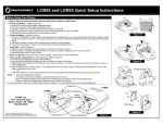
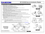
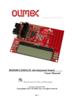
Here the settings for the R11 ~ R18 are displayed. When power is thrown for any resistor
besides R13~R15, they will be sampled at the time NMI is reinstated. After that, there will be no
problems with operation even if the settings are changed; however the settings will become invalid.
0
PCB bottom view
R11
R12
R13
R14
R15
R16
R17
R18
R: Initial Setting
Data Length (R18)
1 8 bit 0 7 bit
Parity (R17)
1 None 0 Even
Control Line Extension Mode (R16)
Serial Settings
(bps, data length, parity)
Condition for starting discovery
(primary channel)
Condition for permission to
Connect (secondary channel)
1
Self
channel
Settings
When DSR : ON, CTS : ON 0
Settings from partner channel
R13~R15
---
RS-232C Communication Speed Setting (R13,R14,R15)
000
9600 bps
100
19200 bps
010
38400 bps
110
57600 bps
115200
bps 001
IrDA operation mode configuration (R11,R12)
00
Reserver
10
primary channel
01
secondary channel
primary / secondary 11
It is possible to select the primary channel mode, secondary channel mode, and the primary channel as
well as the secondary channel according to the settings of R11 and R12.
Operation mode
mode setting terminal
Reservation
R11
R12
0R
0R
primary channel
0R
secondary channel
0R
Primary / secondary channel
! " ##
It is possible to set the RS-232C communication speed with R13, R14, and R15.
However when the control line extension mode of R16 is not installed, the settings will be valid for all
self-channels. But, when it is 0R, if the R11 and R12’s IrDA mode setting is primary or primary /
secondary channel, then the self-channel with be valid. If it is set to the secondary channel, regardless of
the communication speed setting, the other device will set the communication speed. (Figure 2-2).
When the communication rate has established an IrDA link, it will be sampled, so it is okay to change the
speed settings while it is in operation. In the event that the speed is changed while communicating, the
current communication link will be severed and with any following communication the new speed will
become valid.
Figure 2-1
Communication Speed
Communication Speed Setting Terminal
9600bps
R13
R14
R15
0R
0R
0R
0R
0R
19200bps
38400bps
0R
0R
57600bps
0R
115200bps
0R
0R
Figure 2-2
R16
Primary Channel
R12:0R , R11:
0R
Secondary Channel
R12:
, R11:0R
Primary / Secondary Channel
R12:
, R11:
self channel
self channel
self channel
self channel
other channel
self channel
$%
In order to confirm that the device is operating correctly there is an indicate function installed.
By looking at the flash of the LED you can check the state of communication.
There are 2 flashing speeds, during standby on the secondary channel there is no flashing. If the primary
channel commences discovery, it will flash once every 3 seconds (for approx. 0.7 seconds). After
discovering the other device and communication becomes possible it will flash every 0.4 seconds.
Operating condition
LED
during connection standby
Low
during discovery
low speed
flashing once every 3 seconds
flashing
(for approx. 0.7 seconds)
during communication with
high speed
switches from High to Low every 0.4
other device
flashing
seconds
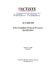
"#
D-sub 9-pin Male connector: (RS-232C)
Pin No.
Name
Descriptions
I/O
1
DCD
Data Carrier Detect
I
2
RxD
Receiver Data
I
3
TxD
Transmitter Data
O
4
DTR
Data Terminal Ready
O
5
GND
Signal Ground
6
DSR
Data Set Ready
I
7
RTS
Request to Send
O
8
CTS
Clear to Send
I
9
RI
Ring Indicator
I
Gnd
*** Electricity source:
a) With Voltage Regulator
b) Without Voltage Regulator
(U6_ is placed, R25 is removed)
(U6_ is removed, R25 is placed)
AC Adaptor DC 7.5V / 300mA above
DC 5V / 450mA above, stable source.
+ DC 5V
–
Gnd
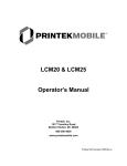
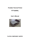
&'(
● Serial Port: When connecting modems etc. to the Data Communication Equipment
(DCE) side, connect the corresponding signal names of the modem and IR100S+.
When connecting to PC’s to the Data Terminal Equipment (DTE) side use a cross
connection for IR100S+ and the PC or Plotter/Printer(with RS232 port).
Example Connection Reference #1: Modem (DCE) Connection
IR100S+ I/F
RxD
RD
< Straight Cable >
RxD :
RD
Modem(DCE)
Data Receiving
Only valid with received data
when the DCD (CD) signal is on.
TxD
SD
TxD :
Data Transmission
SD
Valid with sending data when
RTS (RS), CTS (CS), DSR (DR),
DTR (ER) are on.
/DTR
ER
/DTR :
ER
Data Terminal Ready
Turns on when receiving and
transmitting of data is possible
and when the terminal has power.
/DSR
DR
/DSR :
Data set ready
DR
Turns ON when the modem
is able to send and receive.
/RTS
RS
/RTS :
Transmission Request
RS
Instructs the modem to be in
transmission mode. The terminal is
turned on before the transmission.
/CTS
CS
/CTS :
CS
Transmissible
Indicates that the modem is able to
transmit. When CS is ON the
modem is able to receive.
Example Connection Reference #2: PC Terminal (DTE) Connection
IR100S+ I/F
RxD
(RD)
< Cross Cable >
RxD
(RD)
PC Terminal(DTE)
: Data Receiving
Only valid with received data
when the DCD (CD) signal is on.
TxD
(SD)
TxD
(SD)
: Data Transmission
Valid with sending data when
RTS (RS), CTS (CS), DSR (DR),
DTR (ER) are on.
/DTR
/ DTR
(ER)
(ER)
: Data Terminal Ready
Turns ON when the device
is able to send and receive.
/DSR
/ DSR
(DR)
(DR)
: Data Set Ready
Turns ON when the device
is able to send and receive.
/RTS
/ RTS
(RS)
(RS)
: Transmission Request
Instructs the device to be in
transmission mode. The terminal
is turned on before transmission.
/CTS
/ CTS
(CS)
(CS)
: Transmissible
Indicates that the device is able
to transmit. When CS is ON the
device is able to receive.
Product Name: ACT-IR100S
Compatibility: Fully compatible with IrDA -1.0 Physical spec. and
IrDA-1.0 protocol spec.: IrLAP, IrLMP, IAS, TinyTp, IrCOMM
Specifications of IrDA-1.0 (SIR):
Transmission Speed
Communication
Distance
Radiating Angle
Peak Wave Length of
Radiated Light
Specifications of RS-232 port:
Transmission Speed
Cable Length
Connector
Signal Definition
9.6kbps, 19.2kbps, 38.4kbps, 57.6kbps, 115.2kbps
within 100cm
±15º~±30º (±15 to ±30 degrees)
880~1050nm
9.6kbps, 19.2kbps, 38.4kbps, 57.6kbps, 115.2kbps
110 - 120 cm
DB-9M (DTE) or DB-F (DCE)
DTE or DCE
Power Source: 5 VDC (Stable) or 7.5 VDC (AC adapter).
Power Consumption: Active: < 80mA
Dimensions: 61mmL x 35mmW x 18mmH (2.4"L x 1.4"W x 0.7"H)
Weight: 65 gr. (2.5 Oz)
Operating Temperature: 0° C TO 60° C
Storage Temperature: -20° C TO 85° C
77+9;6?%60+69>@;+,890689708+;$0+
)*
Many PC peripherals use serial cable to communicate with PC. They cannot talk with Infrared Devices,
such as IrDA capable PC, notebooks. ACT IR-100S’s aim is to make those devices into IrDA compatible
product by simply connecting it to their serial port. And these devices with IR100S COM-port IrDA bridge
can communicate with PC wirelessly and don't need to modify neither hardware nor software
This simply test uses two PCs, one is IrDA installed and another is not. Both Run Windows
HyperTerminal Program (one of the communication accessories). You should be able to type on one
keyboard and see results on another PC's screen, or transfer files between them through the infrared
connection.
'(
+(,
PC#1:
HW: x386 or better PC.
ACTiSYS' IR2000B board (based on NS87108A) with IR2000L dongle, or
ACT-IR220L Com-port Adapter, connected to COM1 or COM2.
SW: WIN95/98, IrDA Driver for SIR (if using IR220L) or FIR (if using IR2000B)
HyperTerminal, IR Monitor
PC#2:
HW: x386 or better PC,
ACT-IR100S, DTE-DCE Converter, RS232 Mini Tester (Option)
DC Power Supply (5V stable source or 7.5V adapter for regulator-installed)
SW: WIN95/98, HyperTerminal
,-)
,-
( )
''
)!*+
$%&
$
!" #
"#
+
PC#1:
Install IrDA Driver. The assigned IR virtual port must be COM4 or less, otherwise HyperTerminal
will not be able to connect it
IR Monitor: Speed limit = 115.2K or lower
HyperTerminal: Connect Using -> direct to COM4 (assigned virtual port of IR)
PC#2:
100S:
R11-18 or DSW8-1: 1100, 0111
Primary/Secondary, 9.6k, Self channel setting, 8-N,
HyperTerminal: Connect Using -> direct to COM1 or COM2 (the port IR100S using)
9.6k, 8-n-1, Hardware flow-control
&-
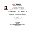
1. Connect all devices as FigA-1
2. Switch on PC#2 and the power supply of 100s.
3. Run HyperTerminal on PC#2. Set its properties according to the above configuration guide (Fig
A-2 ..4).
The LED DTR and RTS of the RS232 Mini Tester should be Red (True) when it is connected. The
DTR will go to Green (False) if you disconnect it. When both DTR and RTS are True (high level) the
100S will begin discovery if you set it to Primary or Primary/Secondary. The 100S' LED will blink once
every 3 seconds.
4. Switch on PC#1.
You will see the IR Found icon and hear the sound of found IR device when windows has started.
Open the IR Monitor, you will see the Status are:
Communicating with
Name: ACTiSYS IR100S-115 (Nickname of 100s, might be different with different version)
Description: Intelligent SIR Adapter
Communication efficiency (…)
Good at 115.2 Kbps (or 57.6 Kbps. Depends on the highest speed both sides can support)
5. Run HyperTerminal on PC#1 now. Set its properties according to the above configuration guide.
Click the Call icon to connect to the assigned IR port. The LED DSR and CTS of the RS232 Mini
Tester on PC#2 side should turn to Red (True) when it is connected and the 100S' LED will blink once
every half second.
6. Type keys on PC#1's keyboard and you should see the results will display on the remote
HyperTerminal's screen. If you have got strange letters, the baud rate you set for the HyperTerminal
is not the same as 100s.
7. File Transfer: Click the menu Transfer and Receive File on PC#1 …
Click the menu Transfer and Send File on PC#2 (Fig A-5)…
The operation is similar to use cable connection.
The real data transfer speed depends on the lower one of IR speed and RS-232 speed. For example,
the IR Speed is limited to 57.6kbps and the RS-232 speed of 100s is 9600, the effective speed
(throughput) is 9570bps (Fig A-6). If the RS-232 speed set to 115.2kbps. The throughput would be
around 5kbytes/Sec.
Figure A-2
Figure A-3
Figure A-4
Figure A-5
Figure A-6
77+9;6?%$60.,26;,
)*
If your device has no built-in modem and wants to connect to Internet, normally you will buy an external
modem and use cable to connect them together. But some mobile devices are so small that have no
RS-232 port for cable connection. Most of them have IrDA wireless built-in interface so that they can
connect with an IrDA modem without cable.
One usage of ACT IR-100S is to make those normal modem into IrDA compatible product by simply
connecting it to their serial port. And these devices with IR100S COM-IrDA bridge can communicate with
PC or your IrDA-cable devices wirelessly and don't need to modify neither hardware nor software
This simply test uses one PC with IrDA adapter with driver installed and an external modem connected
with IR100S. On PC uses 'Make New Connection' wizard of Dial-Up Networking to create a new dial-up
connection to your ISP through the IR modem. It should be able to find the modem, dial phone number,
establish a connection to internet and browse the web.
'(
+(,
PC:
HW: x386 or better PC.
ACTiSYS IR2000B board (based on NS87108A) with IR2000L dongle, or
ACT-IR220L Com-port Adapter, connected to COM1 or COM2.
SW: WIN95/98, IrDA Driver for SIR (if using IR220L) or FIR (if using IR2000B)
Dial-Up Networking, IR Monitor75
External Modem, IR100S, RS232 Mini Tester (Option)
DC Power Supply (5V stable source or 7.5V adapter for regulator-installed)
&
+ , % % ( ) * !
!
& ' % " # $
" "#
+
Connect all devices as Fig B-1.
PC:
Install IrDA Driver.
Configure the Modem: (Fig B-2..6)
Port: Virtual Infrared COM Port
Maximum Speed: 115.2 Kbps
Data bits-Parity-Stop bits: 8-N-1
Use flow control: Hardware (RTS/CTS)
100S:
R11-18 or DSW8-1: 1100,0111
Primary/Secondary, 9.6k, Self channel setting, 8-N,
&%./#
Switch on modem and the power supply of 100s. The CTS and DSR LED on the Mini RS-232 Tester
should change color from Green (False) to Red (True)
Put the two IR dongles face to face. Start up PC Win95/98 and the program IR Monitor should find
IR100S device. (Fig B-8). You will see the IR Found icon and hear the sound of found IR device.
Run Dial-up network connection on PC. Set its properties according to the upper configuration guide (Fig
B-2 ..6).
If a connection is established DTR and RTS are turned ON (Red, True).
Open the IR Monitor, you will see the Connection Status. (Fig B-10)
Start the connect procedure, you will see phone dialing and negotiations. (Fig B-9)
!
6&('%6;7/7..A
!"IrLAP, IrLMP, IAS and optional Tiny TP, IrCOMM, IrMC, IrTran-P, etc.
!"For PDA, digital camera, handheld data terminal, palmtop computer, smart phone.
!"Very tight code, modular design, easy porting and API interface, well supported.
!"Small code size (20 - 40K bytes), well tested and inter-operate with all IrDA devices.
II (A6666&('%6;./7..A
!"IrLAP, IrLMP, IAS and optional Tiny TP, IrCOMM, IrMC, IrTran-P, etc.
!"For printer, pager, docking station, medical device, cell phone, storage devices.
!"Very tight code, modular design, easy porting and API interface, well supported.
!"Small code size (4 - 20K bytes), well tested and inter-operate with all IrDA devices.
,%6;7
!""#$%
%&
'&&$())*
!"&)%#(+
,(
-"%.#*
!""
,#&#$/&,
/%%'
)#//%)*
!"01-%#,
)%%)*
<@<B%6;(7
!"2
#
$)
(#
,)*
)
&%%3
!"-+&(+
,-",
/%.#*
!"4
%%(/
5%
&!6!6%.*
!"%#+
,#,#,&$
7)
&3
$%!60($
!"8
(%'
)829:)
*
!";.(
$+-")%+
,!*<
4/)*
!"4/
$9:*%-"*)#+#
*
!"%%&$%.+
5%
&!%5%
&*
!"9:/)
&%6=
7)
&))(*
THE FOLLOWING WARRANTY GIVES YOU SPECIFIC LEGAL RIGHTS. YOU MAY ALSO HAVE
OTHER RIGHTS THAT VARY FROM STATE TO STATE.
ACTiSYS Corporation warrants to the first consumer purchaser, for a period of 1 year from the date of
purchase, that this wireless interface (The Product? Will be free from defective workmanship and
materials, and agrees that it will, at its option, either repair the defect or replace the defective Product or
part thereof at no charge to the purchaser for parts or for labor.
This warranty does not apply to any appearance items of the Product, any consumable items such as
paper, ink ribbon, or batteries supplied with the Product, or to any equipment or any hardware, software,
firmware, or peripheral other than the Product. This warranty does not apply to any Product the exterior
of which has been damaged or defected, which has been subjected to misuse, abnormal service or
handling, or which has been altered or modified in design, construction or interfacing. Tampering With
Label Voids Warranty.
In order to enforce the rights under this limited warranty, the purchaser should mail, ship, or carry the
Product, together with proof of purchase, to ACTiSYS .
The limited warranty described above is in addition to whatever implied warranties may be granted to
purchasers by law.
To the
extent permitted by
applicable law,
ALL IMPLIED WARRANTIES
INCLUDING THE WARRANTIES OF MERCHANT ABILITY AND FITNESS FOR USE ARE LIMITED
TO A PERIOD OF 1 YEAR FROM THE DATE OF PURCHASE. Some states do not allow limitations on
how long an implied warranty lasts, so the above limitation may not apply to you.
Neither the sales personnel of the seller nor any other person is authorized to make any warranties other
than those described above, or to extend the duration of any warranties beyond the time period
described above on behalf of ACTiSYS Corporation.
The warranties described above shall be the sole and exclusive remedy available to the purchaser.
Correction of defects, in the manner and for the period of time described above, shall constitute full
satisfaction of all claims, whether based on contract, negligence, strict liability or otherwise. In no event
shall ACTiSYS Corporation be liable or in any way responsible, for any damages or defects in the
Product which were caused by repairs or attempted repairs performed by anyone other than ACTiSYS
technician. Nor shall ACTiSYS Corporation be liable or in any way responsible for any incidental or
consequential economic or property damage. Some states do not allow the exclusion of incidental or
consequential damages, so the above exclusion may not apply to you.
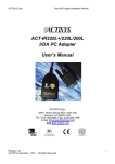
Corpo Corpor
!
"#$%%%
&#$%% %'
(#%)*+,-+
.
#/#00111-+,-+
,/%"
2
-