1
4. MENU SYSTEM:
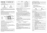
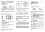
Cycle Parameter Menu
The Parameter Menu System is organized into four basic cycles. This is shown in
the chart below.
Cycle
1 – Indication
2 – Alarms
3 – Configuration
4 – Calibration
Cycle-1
INDICATION
Cycle-2
ALARMS
Cycle-3
CONFIGURATION
Cycle-4
CALIBRATION
PV
Indication
A1SP
Type
Inl[
Alarm 1
Input Type
Input Low Calibration
A2SP
Dp.po
Ink[
Alarm 2
Decimal Point Position
Input High Calibration
AL.RE
Vnit
Differential
Unit
[jl
In.ll
Cold Junction Low
Calibration
Input Low Limit
In,kl
4.1 INITIAL STARTUP
Input High Limit
0ffs
When the controller is initially energized the Firmware version is displayed for
approximately 4 seconds after which the controller reverts to the normal operation
mode in the Indication cycle. The value of the process variable (PV) is displayed
and the outputs are enabled after 6 seconds.
Offset Signal Input
A1fv
Alarm 1 Funtion
A2fv
Important: The Firmware version of the controller must match the version
indicated on the bottom front cover of this manual.
Alarm 2 Funtion
A1ky
Alarm 1 Hysteresis
4.2 SETUP CYCLE PARAMETER ACCESS:
A2ky
Alarm 2 Hysteresis
The Indication cycle is the default cycle for the controller and only shows the PV.
All other cycles have parameters that can be accessed and changed to configure
the controller as needed.
The cycles need only to be accessed when a change of parameters is necessary.
To reach the other parameters the user must keep the SETUP key pressed for
approximately 4 seconds. After this time the controller will display the first
parameter of the next cycle. By keeping the SETUP key pressed for another 3
seconds the next cycle will be accessed.
Release the SETUP key when the desired cycle is reached. Press the SETUP key
once to access the next parameter in the same cycle or quickly press the SETUP
key to move through the parameters in the cycle. After the last parameter in a
cycle is reached, pressing the SETUP key one last time will bring the controller
back to the Indication cycle (Cycle-1). The display will also revert to the
Indication cycle after 20 seconds if the parameters in a cycle are not changed.
Prot
Security Protection
NOTE: Any changed parameter is saved into non-volatile memory when
scrolling to the next parameter or 20 seconds after the new parameter is
changed.
4.3 DIGITAL SERIAL NUMBER ACCESS:
Once in a desired parameter the display will alternate the name and value. The
or
value can then be changed by pressing the
key.
To read the controller’s serial number (8 digits), hold down the
key for a few
seconds and the first four digits will appear on the display. To read the second four
key for a few seconds and the second four digits will
digits, hold down the
appear on the display, completing the 8 digits serial number.
The following page shows the Cycle Parameter Menu.
The serial number is recorded in the factory and cannot be changed.
8
9