1
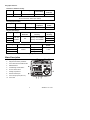
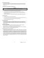
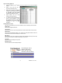
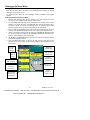
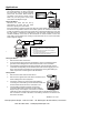
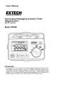
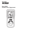
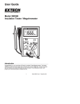
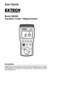
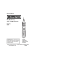
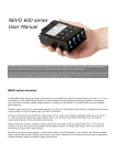
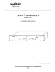
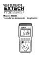
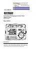
99 Washington Street
Melrose, MA 02176
Phone 781-665-1400
Toll Free 1-800-517-8431
Visit us at www.TestEquipmentDepot.com
Back to the Extech 380366 Product Page
User's Manual
Autoranging Datalogging Insulation Tester
(Megohmmeter)
with PC Interface
Model 380366
Introduction
Congratulations on your purchase of the Extech 380366 Datalogging Insulation Tester.
The 380366 measures insulation resistance to 4000MΩ and includes Continuity and
Voltage tests. The built-in datalogger remotely stores approx. 16,000 readings for later
transfer to a PC. The tester can also take and record readings to a PC in real time. This
professional tester, with proper care, will provide years of safe reliable service.
Safety
1.
Circuits under test must be de-energized and isolated before connections are made
(except for voltage measurements).
2.
Circuit connections must not be touched during a test. Use extreme caution when
working near bare conductors and bus bars. Accidental contact with conductors could
result in electrical shock.
3.
Use caution when working near voltages above 60VDC or 30VACrms.
4.
After insulation tests, capacitors must be discharged.
5.
Test leads (including alligator clips) must be in good working order, clean and without
broken or cracked insulation.
6.
When servicing, use only specified replacement parts.
International Safety Symbols
Caution, refer to this manual before using this meter
Dangerous Voltages
Meter is protected throughout by double or reinforced insulation
Specifications
General specifications
Display
Backlit 3-3/4 digit (4000 count) LCD with analog indicator
Sampling rate
2.5 samples/sec. (digital); 10 samples/sec. (analog)
Audible Continuity
Low resistance range with audible continuity < 40Ω
Over range indicator
"OL” displayed when measurement exceeds range limits
Low battery indicator
" - +" symbol displayed when battery voltage is low
Datalogger memory
16,000 readings
Datalogger Sample
Rate
Programmable: 1 to 65,400 sec/sample or single manual
record
Power source
Eight 1.5V AA cells
Power consumption
20 to 90mA depending upon function (40 hours typical)
Environmental
CAT III; Altitude: 2000 meters; for indoor use only
Operating conditions
32 to 104 F (0 to 40 C); < 80% RH
Storage conditions
14 to 140 F (-10 to 60 C); < 80% RH
Dimensions/Weight
7.5 x 5.5 x 3” (190 x 140 x 77mm) / 2 lbs (900g)
o
o
o
o
Environmental specifications
• Installation Category III 600V
• Pollution Degree 2
• Altitude up to 2000 meters
• Intended for indoor use only
2
380366 V1.6 11/04
Range Specifications
Resistance / Audible Continuity
Range
Resolution
400 Ω
Accuracy
0.1 Ω
Max. open
circuit voltage
±1%rdg + 5d
12.8V
Overload
Protection
220Vrms
Audible tone when Resistance <40Ω;
Short circuit current: 280mA (min. 200mA)
AC Voltage (40 to 500Hz)
Range
Resolution
Accuracy
Input
impedance
Overload
Protect.
600VAC
1V
±1.5%rdg + 3d
4.5MΩ
750Vrms
Megohm (Auto Range)
Voltage
250V
500V
Ranges
4, 40, 400,
4000MΩ
Maximum
Resistance
Voltage
Resolution
Accuracy
Accuracy
±3%rdg + 5d (<2000MΩ)
1kΩ
±5%rdg + 5d (>2000MΩ)
1000V
Voltage
Range
1mA Test Current
250V
500V
+20% ~ -0%
+20%~ -0%
+10%~ -0%
Short Circuit
Current
@250KΩ
4000MΩ
@500KΩ
< 1.5mA
1000V
@1MΩ
o
o
Note: Accuracies are specified as % reading + digits at (73°F ± 9°F) 23 C ±5 C < 80% RH
Meter Description
1.
LCD Display
2.
Megohmmeter TEST pushbutton
3.
Test LOCK and DATA HOLD button
4.
RECORD button
5.
LCD Backlight / Wake button
6.
Function select switch
7.
Storage compartment
8.
RS-232 interface jack
9.
Test Lead input jacks (HI & LO)
10. Test Leads
3
380366 V1.6 11/04
Operation
Warning
Ensure that the circuit under test does not include components that can be damaged by 1000VDC; such
devices include power factor correction capacitors, low voltage mineral insulated cables, electronic light
dimmers, and ballasts/starters for fluorescent lamps.
Connecting Test Leads
For all functions (Megohmmeter, Resistance, Continuity and AC Voltage), connect the red
test lead to the HI terminal and the black lead to the LO terminal.
Test Lead Check
1.
Connect the red test lead to the HI input terminal; black lead to the LO terminal.
2.
Set the rotary switch to the resistance/ continuity position ( .
3.
Touch the test lead tips together. Resistance should be less than 1Ω and the audio
tone should sound.
4.
With the leads not touching, the display should read “-OL-“. (over range).
5.
If any readings are displayed other than the readings just described, the test leads
should be considered faulty and must be replaced before using the meter. Failure to
do so could result in damage to equipment and electrical shock.
Ω)
Insulation Resistance Measurements (Megohmmeter Tests)
Warning: Do not perform Insulation Resistance measurements if AC Voltage is present on circuit under test.
1. Connect the red test lead to the HI input terminal; black lead to the LO terminal.
2.
Set the rotary switch to the desired function.
3. Connect the tips of the test leads to the equipment under test.
4. Press and hold down the red TEST button. Release the test button to stop the test. The
meter will then hold the resistance reading. This is indicated by the H icon in the upper
left corner of the display.
5. To clear the display, press the LOCK/HOLD button twice.
Note that the charge stored on the device under test will be automatically discharged
when the testing process is finished
3-Minute Test
For hands-free operation, use the Test Lock feature.
1. Connect the red test lead to the HI input terminal; black lead to the LO terminal
2.
Set the rotary switch to the desired function.
3.
Connect the tips of the test leads to the equipment under test.
4.
Press the LOCK button. The LOCK icon will be displayed. Press the red TEST button.
A 3-minute continuous test will begin. The red TEST button can be pressed at any
time to end the test. If the TEST button is not pressed the meter automatically stops
the test after 3 minutes. The meter will then hold the resistance reading. This is
indicated by the H icon in the upper left corner of the display.
5.
To clear the display, press the LOCK/HOLD button twice.
Note: The
symbol will appear in the upper right corner of the display and an audible
tone will sound whenever the high voltage is applied to the test leads.
4
380366 V1.6 11/04
Analog Bargraph Display
The bargraph can indicate up to 10GΩ. When the measured value is between 4GΩ and
10GΩ, the LCD displays "-HI-". When the measured value is higher than 10GΩ the LCD
displays "-OL-".
Low Resistance and Audible Continuity Tests
WARNING
Do not run this test unless ACV = 0. Do not use this mode to check diodes.
1. Set the Rotary switch to the audible continuity/resistance position.
2. Connect the red test lead to the HI input terminal; black lead to the LO terminal.
3. Connect the tips of the test leads to both ends of the circuit under test and read the
resistance on the LCD.
4. When the resistance of a circuit is less than approx. 40Ω an audible tone will sound.
AC Voltage Tests
1. Set the Rotary switch to the red ACV position.
2. Connect the red test lead to the HI terminal and the black test lead to the LO terminal.
3. Connect the other end of the test leads to the circuit under test.
4. Read the voltage value on the LCD.
Data Hold Function
The Data Hold function freezes the displayed reading. Data Hold works automatically on
Insulation Resistance Measurements (Megohmmeter tests) but, for the other tests, the
user must press the HOLD key to freeze the meter reading. Press HOLD again to exit the
Data Hold mode.
Auto Power OFF Feature
After a 30-minute period of non-use, the meter automatically shuts down. This will
conserve battery life. To wake the meter, press the Backlight button.
Note that the meter is not completely off until the function switch is set to the OFF position.
Always turn the switch to the OFF position when not in use.
Application Note for Large Installations
In large wiring installations where the insulation of outlets is being tested, more than one
insulation resistance measurement may have to be made to take into account parallel
resistances. Divide large systems into subgroups and test subgroups individually. Also, in
large installations, the capacitance of the insulation will be high, thereby taking longer to
charge when being tested. Care must be taken not to finish a measurement until the
insulation capacitance is fully charged (a steady, stable reading is an indication that this is
the case). The charge stored in the insulation after a test will be discharged automatically
when the test button is released. Be careful not to turn the range switch while the test
button is pressed.
5
380366 V1.6 11/04
Built-in Datalogger
The meter can store approx. 16,000 readings in the built-in datalogger. Readings are
grouped in ‘SETS’. Each recording session constitutes a ‘SET’. Recording a new set does
not erase a previously recorded set.
The readings remain in the datalogger memory even when power to the tester is off (as
long as the batteries are fresh). Readings can be transferred, at a later time, to a PC. Use
the meter’s RECORD button to operate the meter’s Datalogger in the following ways:
a. Clearing Datalogger memory
1. Press and hold the RECORD button while turning the meter on.
2. Release the RECORD button when
r (clear) appears on the display. The entire
datalogger memory will now be erased.
b. Capturing one data point
Press the RECORD button for one second to capture one reading. The REC display
icon will briefly appear at the top of the LCD and the large digits will flash the data point
number (the recorded measurements are numbered). Each reading captured by this
method is considered a Set.
c. Capturing a continuous stream of data points
1. Press and hold the RECORD button for approx. 3 seconds until a long tone is heard.
The REC display icon will appear and remain on the display for as long as the
recording session lasts.
2. To stop recording, press the RECORD button again. The REC indicator will switch
off. Each group of readings captured in this manner is considered a Set.
3. Readings will be taken every 2 seconds (default sampling time). To change the
sampling time, refer to the section ‘Datalogger Software Mode’.
The following sections cover meter-to-PC data downloading & other PC interface features.
6
380366 V1.6 11/04
PC Interface
Minimum hardware requirements
486 PC or better with CD-ROM drive
Communications Settings
Baud Rate: 9600, Parity: None, Data bits: 8, Stop bits: 1
Connecting the meter to a PC
Connect one end of the supplied cable to the PC Com Port (DB9 connector) and the other
end (infrared connector) to the top of the meter.
Installing Software (compatible operating systems: Windows
TM
95, 98, 2000, Me, & XP)
1.
Insert the supplied CD-ROM in the PC’s CD-ROM drive.
2.
The SETUP program will run automatically. If not, press the Windows START key
and select RUN. Then type SETUP at the prompt and press the ENTER key.
3.
Follow the on-screen instructions for the setup program.
TM
Running the Software
1.
Open the ‘Insulate’ program using the program icon.
2.
Select PC communications port COM1 or COM2 when prompted.
3.
The Program screen will appear as a facsimile of the meter's front panel (see below).
Sampling
Time
Control
Icons
System
Time
Meter
display
Function
Switch
Com.
Status
Meter
buttons
Data Acquisition and Datalogger modes
These two modes of operation, distinctly different, are explained in detail separately.
For the Data Acquisition mode of operation, the meter must be connected to the PC. In this
mode, readings taken by the meter are displayed and stored on the PC.
In the Datalogger mode, the meter records data remotely then, at a later time, the meter is
connected to the PC and the readings are transferred. Instructions for datalogging were
covered in the previous section. Instructions for transferring data and navigating the
software are given below.
7
380366 V1.6 11/04
Test Equipment Depot - 800.517.8431 - 99 Washington Street Melrose, MA 02176
FAX 781.665.0780 - TestEquipmentDepot.com
Data Acquisition Software Mode
As explained above, the Data Acquisition feature allows the user to connect the meter to
the PC and take and record readings simultaneously. With the meter connected to the PC
and with the software running, follow the steps below:
System Time Set
Click the computer icon from the row of Control Icons at the top of the main software
screen. This is the SYSTEM TIME SET button. The PC system date and time will now be
shared by the software program. Note that if your PC date and time are not set correctly,
do so at this time. The system time will be shown on the main software screen.
Input ID Code
The ID Code is used as a reference number specific to a particular data acquisition
session. The ID Code does not affect the software other than allowing the user to match a
set of data to a unique ID. See the LOGGER screen at right
1. Select MEMORY from the OPTION menu
on the main software screen.
2. Highlight the number in the ID Code field
and type a new reference number. Valid
numbers are 0 through 9999.
3. Click the ID Code button.
Sampling Time
The Sampling Time tells the software how
often to log a reading. The sampling time can
be set from 1 to 65,400 seconds. See the
LOGGER screen at right.
1.
Click on the ‘wrist-watch’ icon from the
row of Control Icons on the main
software screen.
2.
Highlight the existing value in the
SAMPLING field.
3.
Type in the desired sampling time.
4.
Click the Sampling button when finished.
Creating a File to store data
1.
Click the ‘floppy disk’ icon from the row of Control Icons on the main software screen
and type a unique filename when prompted.
2.
This File can later be opened by clicking on the ‘folder’ icon (4 from left) from the row
of Control Icons on the main software screen.
3.
Saved files can be opened in spreadsheet programs as *.dat text files by opening the
spreadsheet application, selecting OPEN FILE, choosing ALL FILE TYPES, and
locating the file previously stored.
th
Start and Stop Recording
nd
1.
Click the ‘red’ icon (2 from left) from the row of Control Icons on the main software
screen to start recording. If a file has not been set up at this point, the software will
prompt for a file name.
2.
Data will now be logged every n seconds (where n is the programmed sampling time).
3.
To stop recording, click the ‘black’ icon (3 from left) in the row of Control Icons.
rd
8
380366 V1.6 11/04
Test Equipment Depot - 800.517.8431 - 99 Washington Street Melrose, MA 02176
FAX 781.665.0780 - TestEquipmentDepot.com
Open an existing Data File
th
1.
Click on the ‘folder’ icon (4 from left) in the row of Control Icons on the main software
screen.
2.
Select a file from the list
previously stored files (if any).
3.
When a file is opened, its data list
will appear containing the date/time
for each reading, measurement, unit
of measure, and low battery
indication (see diagram at right).
4.
Select PRINT from the
heading to print the data list.
5.
To import the data to spreadsheet or
rd
other 3 party application: Locate
and open the file as a text file
(filename.dat) using the FILE OPEN
rd
commands
in the
3
party
application.
of
menu
Soft-key Remote Control
Use the four front-panel keys on the main software screen to remotely control the meter:
TEST button
Click to start a megohmmeter test.
LOCK button
Click to lock the test for 3 minutes (read about the LOCK function earlier in this manual).
HOLD button
Click to freeze the displayed reading. The ‘H’ display icon will appear while the meter is in
the Data Hold mode. Press HOLD again to exit this mode.
REC button
Click to put the meter into continuous recording mode. Readings will be kept in the open
file. If a file is not open, the software will prompt for a file name.
rec button
Click to record one reading to the open file.
Backlight button
Click to activate the meter’s display backlight.
99 Washington Street
Melrose, MA 02176
Phone 781-665-1400
Toll Free 1-800-517-8431
Visit us at www.TestEquipmentDepot.com
Back to the Extech 380366 Product Page
9
380366 V1.6 11/04
Datalogger Software Mode
Datalogging
Instructions for storing data in the meter’s built-in datalogger are provided in the ‘Built-In
Datalogger’ section of this manual.
The following section details all of the datalogger functions available in the supplied
software.
Datalogging Software Window (LOGGER)
rd
1. From the main software screen, click the ‘datalog’ icon (3 from right) from the row of
Control Icons. The LOGGER window will open (shown below).
2. To set the SAMPLING TIME (rate at which datalogger stores readings), type a number
between 1 and 65,000 seconds in the SAMPLING field. Note that the meter must be
connected to the PC in order for the Sampling Time to be transferred to the meter.
Once the sampling time is set, the meter will datalog at the rate selected.
3. Click the TIME OF RECORDING button to download all of the data sets from the meter
to the PC. The data lists will appear as shown on the logger window diagram below.
4.
Select a set of data by clicking on the set number. The NUMBER OF SET field informs
the user as to which set is selected. The NUMBER OF RECORDS field lets the user
know the number of readings in the selected set.
5. The MEMORY and REMAINING fields inform the user as to the total memory capacity
(32K) and the remaining memory.
6. Press the SHOW DATA button to view the raw data. Once the data opens for the
selected set, the user can save or print the data by selecting SAVE or PRINT from the
menu options.
Size of
overall
memory
Remaining
storage space
User ID Code
& Sample rate
System
Date &
Time
Click to
download all
stored sets
Number of data
sets in memory
List of all
loaded sets
Number of
records in
selected set
Click a
number to
select a set
Click to view
data for the
selected set
10
380366 V1.6 11/04
Test Equipment Depot - 800.517.8431 - 99 Washington Street Melrose, MA 02176
FAX 781.665.0780 - TestEquipmentDepot.com
Applications
Measuring Power Tools and Small Appliances
This section applies to any device under test
that uses a line cord. For double insulated
power tools, the meter’s leads should be
connected to the device’s housing (chuck,
blade, etc.) and the ground of the power
cord. Refer to the diagram at right.
Appliance
Testing AC Motors
Disconnect the motor from the line by
disconnecting the wires from the motor
terminals or opening the mains switch.
If the mains switch is opened, and the motor also has a motor-starter, then the starter must
be held in the ON position. With the mains switch opened, the measured resistance will
include the resistance of the motor wire and all other components between the motor and
the main switch. If a weakness is indicated, the motor and other components should be
checked individually. If the motor is disconnected at the motor terminals, connect one
meter lead to the grounded motor housing and the other lead to one of the motor leads.
Refer to diagram at below.
Motor
Mains
Switch
Starter
GND
LINE
Notes:
1. The STARTER must be in the ON position during
the test.
2. The motor-to-meter connection must be made to
the motor housing (ground).
3. The meter-to-main switch connection must be to the
motor side of the main switch as shown.
Testing DC Motors
1.
Disconnect the motor from the line.
2.
To test the brush rigging, field coils and armature, connect one meter lead to the
grounded motor housing and the other lead to the brush on the commutator.
3.
If the resistance measurement indicates a weakness, raise the brushes off of the
commutator and separately test the armature, field coils and brush rigging (one at a
time). Leave one lead connected to the grounded motor housing while testing the
motor components. This also applies to DC Generators.
Testing Cables
1.
Disconnect the cable under test from the line.
2.
Disconnect the opposite end of the cable to avoid errors as a
result of leakage from other equipment.
3.
Check each conductor to ground and/or lead sheath by
connecting one meter lead to ground and/or lead sheath and
the other meter lead to each of the conductors in turn.
4.
Check insulation resistance between conductors by
connecting meter leads to conductors in pairs. Refer to
diagram at right. In the diagram, note that the 3-conductor
cable has two wires shorted to the ground shield. This two-wire/shield connection is
then connected to one side of the meter. The remaining conductor is connected to the
other side of the meter.
11
380366 V1.6 11/04
Test Equipment Depot - 800.517.8431 - 99 Washington Street Melrose, MA 02176
FAX 781.665.0780 - TestEquipmentDepot.com