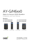
1
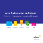
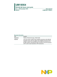
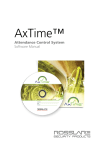
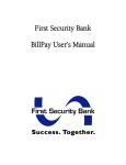
Home Automation by Reliant
Install Guide & User Manual
Thermostat
rev 08/15
Smart Plugs
smart Bulbs
Range Extender
Gateway
Thermostat compatibility
The Reliant thermostat works with most 24-volt heating and cooling
systems, including gas, electric, oil, solar, hot water, geothermal, forced
air, heat pump, and radiant. However, there are a few systems that are
incompatible.
Incompatible systems include:
• HVAC systems with high-voltage controls. If your old thermostat is
labeled 120V or 240V, is mounted in a junction box, or is connected to
thick wires using wire nuts, your system is not compatible.
• Systems with variable-speed fans. Check your HVAC documentation
Please read through
these instructions before
you begin installation of
your Reliant thermostat.
to confirm.
• At this time, humidifiers and dehumidifiers are not fully supported by the
Reliant thermostat.
• Proprietary systems such as:
– Carrier Infinity
– Bryant Evolution
– Lennox iComfort
– Honeywell Redlink
NOTE: HVAC systems do not follow a standard for control wiring. The 24V common wire,
the 24V transformer power supply wire(s), and the 24V heat pump reversing valve power
supply wire are labeled differently in some systems.
If your system is incompatible, do not attempt to install the
Reliant thermostat. If you are unsure about compatibility
or just want someone else to install it, professional
installation is available. Call us at 1.855.457.5700 for more
information.
Contents
Install Guide
Ready to teach your house some new tricks?
Getting to know your devices................................................................................................ 2
Setting up your system
Step 1: Installing your new Reliant thermostat................................................................. 4
Step 2: Pairing your Reliant thermostat............................................................................10
Step 3: Setting up smart plugs............................................................................................12
Step 4: Setting up smart bulbs............................................................................................14
Step 5: Pairing and using your range extender................................................................16
Step 6: Connecting the gateway to the Internet............................................................18
Step 7: Setting up your account..........................................................................................18
User Manual
Configuring your system
Adjusting your thermostat settings..................................................................................19
Creating thermostat schedules.........................................................................................20
Creating thermostat rules and alerts................................................................................21
Advanced configuration.......................................................................................................23
Setting up your smart plugs/smart bulbs.........................................................................24
Grouping your smart plugs/smart bulbs..........................................................................24
Putting your smart plugs/smart bulbs on a schedule...................................................25
Using the Reliant Connect app................................................................................................26
Setting up Location Services.....................................................................................................29
Appendix
Frequently asked questions.......................................................................................................30
Troubleshooting............................................................................................................................34
Thermostat wiring guide..................................................................................................... 36
1
Ready to teach your house some new tricks?
Welcome to Home Automation by Reliant. Get connectivity, control, and energy
management from a smarter house. This guide will walk you through everything you need
to get your gateway, smart plug, range extender, thermostat, and smart light bulbs up and
running.
If you didn’t purchase all of these, skip the steps associated with their installation.
Getting to know your devices
smart bulb
gateway
Ethernet cable
Reliant thermostat
range extender
smart plug
The gateway is the hub that allows your new smart
light bulbs, thermostat, and smart plug access to the
Internet.
The range extender strengthens network connectivity
and maximizes reliability.
2
Home Automation by Reliant | Install Guide & User Manual
Plug lamps and other devices into your smart plug to
control them remotely.
To schedule professional installation of your
Conserve with thermostat package, call
1.855.457.5700
Easily control your home
heating, cooling, and lighting
anytime from anywhere with
the Reliant Connect app.
thermostat trim plate
thermostat base plate
thermostat display
screws
4 AA alkaline batteries
screw anchors
wire labels
Your new thermostat can be controlled manually but is at
its best when managed remotely via the web portal and app.
What you need to get started:
▪ All packages require Internet access via a
home broadband router
Thermostat packages also require:
▪ Access to your home’s main circuit breaker panel,
HVAC compressor and air handler
▪ The tools shown above
▪ 3/16” drill bit for use with wall anchors
Questions? Visit support at reliant.com/connectsupport, or give us a call at 1.844.295.5556
3
Install Guide
Setting up your system
Step 1: Installing your new Reliant thermostat
Before you install, confirm your existing HVAC system is working properly. If anything in your existing system
does not work, consult an HVAC technician and have any necessary repairs completed prior to installation of
your thermostat.
1 Locate and turn OFF all circuit breakers associated
with your HVAC system. Please note that your circuit
breakers may have different labels such as furnace,
AC, HVAC, blower, compressor, heater, etc. If you can’t
identify which circuit breakers to turn off, turn off the
main circuit breaker to your whole house.
2 Some HVAC systems also have a circuit breaker or
switch located by the compressor. If present, this circuit
breaker must also be turned OFF at each compressor.
3 Check near the air handler (usually in the attic) for
a switch that controls the fan. This switch may be
labeled furnace, AC, blower, fan, or something similar. If
present, this switch must also be turned OFF.
4 Adjust the temperature on your old thermostat to
confirm that your system is off. All circuit breakers and
switches must remain OFF until thermostat installation
is complete.
NOTE: Failure to follow these instructions may result in
damage to your HVAC unit.
4
Home Automation by Reliant | Install Guide & User Manual
5 Unscrew or unclip the faceplate of your old thermostat
and remove it from the wall.
7 Disconnect and straighten each wire from the old
baseplate.
If a C wire is connected, disconnect and straighten it first.
Avoid letting any disconnected wires slip back into the
wall.
< Snap a pic in
case you need
it for reference.
TIP: As an added precaution, consider covering the exposed
wire ends with electrical tape before removing the old
thermostat baseplate from the wall. Then remove tape from
each wire as you insert it into the new thermostat.
6 Use the pre-labeled stickers that came with your kit to
label each wire with the letter or letters matching the
terminal it is connected to.
NOTE: Some manufacturers and HVAC systems use unique
designations (for example, X1, T1, 1, 2, 3, B). Consider
contacting an HVAC installer if you do not know how your
HVAC system is configured.
If your old thermostat has jumper wires (these may appear as
shorter wires that connect wire ports) and you are unsure of
your HVAC system type, consider professional installation.
8 If needed to cover existing holes or marks from the old
thermostat, place the provided trim plate on the wall
(smooth side out), then attach the new base plate using
a pencil and the level in the plate to mark where the
screws will go. Feed the wires through the hole in the
center of the base plate and attach the base plate to the
wall with the provided screws (and anchors if needed).
Questions? Visit support at reliant.com/connectsupport, or give us a call at 1.844.295.5556
5
wire ports
terminal
springs
jumper
9 Ensure 1/4” of clean exposed wire is showing. If a C wire is present, insert it first. Ensure that the wires
have been fully inserted into the connectors by tugging on each wire AFTER it has been inserted.
When fully inserted, the wire will remain connected. If the wire remains loose, you may need to
ensure that the wire is straight and has enough exposed wire. To remove wires, depress the terminal
spring and pull the wire out of the connector.
6
Home Automation by Reliant | Install Guide & User Manual
Wiring guidelines
If your old thermostat had only one R wire going into RC, RH, or R, how the other wires were
connected to your old thermostat will determine how the single R wire is connected to your
thermostat.
• If no Y wire was connected to your old thermostat, connect the R wire to RH.
• If no W wire was connected to your old thermostat, connect the R wire to RC.
• If a Y wire and a W wire were connected to your old thermostat, connect the R wire
to either RH or RC.
• Do not remove the jumper (circled in the picture to the left) from your base plate.
If your old thermostat had separate RC and RH wires, make sure you pull down on the jumper
(circled in the picture to the left) to remove it from the base plate. Then connect your RC wire to
the connector labeled RC and your RH wire to the connector labeled RH.
Failure to remove the jumper from the base plate when separate RC and RH wires are
present will damage your HVAC system.
Do you have a heat pump with an O and B wire but no C wire? In a standard heat pump system,
the C wire provides 24V power while the O and B terminals are used to power the reversing valve
in a heat pump. However, some manufacturers have used O or B as the C wire in certain models.
If you have a heat pump and do not know how your HVAC system is configured, contact an HVAC
installer. Installing an O or B wire that has been configured as a C wire could damage your heat
pump transformer.
Don’t connect any extra wires that weren’t connected to the old thermostat. If your existing wires
were connected to wire terminals that do not exist on your thermostat, consider a professional
installation or call technical support at 1.844.295.5556.
Please refer to the appendix for a wiring diagram.
Questions? Visit support at reliant.com/connectsupport, or give us a call at 1.844.295.5556
7
10
11 Double-check you have installed and wired your
Press any excess wire slack back into the wall to allow
for clearance of the thermostat. Install the provided
thermostat properly. Then turn the attic fan switch (if
AA batteries in the new thermostat body. Ensure that
present) back ON first, then turn ON all of the HVAC
the thermostat is turned OFF by pressing and releasing
circuit breakers you turned OFF during installation.
the mode (middle) button on the thermostat to cycle
through the different modes until only the temperature
and no other icons are displayed. Then firmly press the
thermostat into the base plate, ensuring the pins on the
thermostat are aligned correctly with the header on the
base plate.
NOTE: Use only new alkaline batteries for the thermostat.
Batteries should be replaced annually.
Recycle your old thermostat responsibly,
as some thermostats contain mercury.
Contact the Thermostat Recycling
Corporation at thermostat-recycle.org for
more information.
8
Home Automation by Reliant | Install Guide & User Manual
Manual thermostat operation
To turn the temperature up,
press the UP button.
Press any button to
view current mode and
temperature. After five
seconds, the display
will turn off.
Pressing the center button will
allow you to cycle through the
heat, cool, auto, or off modes.
The HEAT icon is
displayed in HEAT MODE.
To turn the temperature down,
press the DOWN button.
Both the HEAT and COOL
icons display in AUTO MODE.
The COOL icon is
displayed in COOL MODE.
The LINK icon is
displayed during wireless
configuration.
Questions? Visit support at reliant.com/connectsupport or give us a call at 1.844.295.5556
9
Step 2: Pairing your Reliant thermostat
add/remove button
1 Bring your gateway to the outlet nearest to your
thermostat, and connect it to the outlet. (You will
need simultaneous access to both devices.)
NOTE: At this point, the gateway does not need to be
connected to the Internet. When the gateway is first
plugged in, all of the LEDs may flash momentarily. Please
wait until only the green link is blinking before attempting
to pair devices with the gateway.
2 Ensure that the thermostat is still turned OFF by
pressing and releasing the mode (middle) button
on the thermostat, cycling through the available
modes until only the temperature is displayed.
10 Home Automation by Reliant | Install Guide & User Manual
3 Tap the Add/Remove button on the back of the gateway.
The gateway’s yellow light will begin to blink. If the red
light begins to blink, you have held the Add/Remove
button down for too long. Tap the button again to reset
so that only the green light is blinking.
down button
link icon
4 While the yellow light on the gateway is blinking, press
and hold the DOWN button on the thermostat until the
LINK icon begins to blink. Release the DOWN button
after the icon begins to blink.
NOTE: If you continue to hold the DOWN button, the link icon
may turn red. This will not affect pairing.
5 When the yellow light on the gateway remains
illuminated, the thermostat is added to the network.
NOTE: If you attempt to pair a thermostat that was previously
paired, the link icon will appear RED.
Questions? Visit support at reliant.com/connectsupport, or give us a call at 1.844.295.5556 11
Step 3: Setting up smart plugs
1 Plug the smart plug into an outlet near the device
(such as a lamp) you wish to control remotely.
4 Bring your gateway to the outlet nearest to your
smart plug, and connect it to the outlet. (You will need
simultaneous access to both devices.)
NOTE: At this point, the gateway does not need to be
connected to the Internet. When the gateway is first plugged
in, all of the LEDs may flash momentarily. Please wait until only
the green link is blinking before attempting to pair devices with
the gateway.
2 Plug your device into the smart plug outlet that has the
Z-Wave logo. This outlet gives your device access to
the network.
3 Turn the device on. You will turn it on/off via the network
later.
NOTE: The smart plug outlet without the Z-Wave logo provides
power but is not controlled by the network.
12 Home Automation by Reliant | Install Guide & User Manual
This smart plug is not intended for use
with large appliances. Devices plugged
into the smart plug’s networked outlet
must not exceed 600 watts. Total load
capacity for both outlets is 1,800 watts
(15 amps).
When adding plugs to the network, tap the
Add/Remove button only once. Don’t hold the
button down.
add/remove button
5 Tap the Add/Remove button on the back of the
gateway. The gateway’s yellow light will begin to blink.
If the red light begins to blink, you have held the Add/
Remove button down for too long. Tap the button again
to reset so that only the green light is blinking.
Keep your smart plugs plugged in! Once
your smart plugs have been added to the
network, they will also function as network
range extenders. Even if they’re not used to turn
attached devices on or off remotely, they will
improve network signal strength as long as they
are plugged in.
pairing button
6 While the gateway’s yellow light blinks, tap the button
on the front of your smart plug. When pairing is
complete, the yellow light on the gateway will stop
blinking and remain lit. The red and green lights may
briefly flash before the yellow light turns solid. If the
yellow light on the gateway does not stop blinking, try
tapping the button on the smart plug again.
Not sure if your devices have been successfully
paired? You can check pairing status after
Step 6 (Connecting the gateway to the Internet)
by logging in to the web portal.
Questions? Visit support at reliant.com/connectsupport, or give us a call at 1.844.295.5556 13
Step 4: Setting up smart bulbs
1 Turn off the fixture or lamp to be used with the
smart bulb.
2 Screw the smart bulb into the socket, and leave
the fixture turned OFF.
3 Bring your gateway to the outlet nearest your smart
bulb, and plug it in. (You will need simultaneous access
to both devices.)
add/remove button
4 Tap the Add/Remove button on the back of the
gateway. The gateway’s yellow light will begin to blink.
If the red light begins to blink, you have held the Add/
Remove button down for too long. Tap the button again
to reset so that only the green light is blinking.
NOTE: At this point, the gateway does not need to be
connected to the Internet. When the gateway is first plugged
in, all of the LEDs may flash momentarily. Please wait until only
the green link is blinking before attempting to pair devices with
the gateway.
14 Home Automation by Reliant | Install Guide & User Manual
5
6 When the gateway’s yellow LED blinks, turn the light
fixture ON. When pairing is complete, the smart bulb
will blink twice, and the yellow LED on the gateway will
stop blinking and remain lit. The green and red LEDs
may also blink briefly. If the yellow LED on the gateway
does not stop blinking, repeat steps 1 through 4.
Helpful Hint: If using the smart bulb in
a lighting fixture or lamp connected to a
switched electrical outlet, follow the included
instructions to install the switch lock on the
switch to prevent interrupting power to the
outlet.
When adding bulbs to the network, tap the
Add/Remove button only once. Don’t hold the
button down.
Keep your smart bulbs plugged in! Once
your smart bulbs have been added to the
network, they will also function as network
range extenders. Even if they’re not used to turn
attached devices on or off remotely, they will
improve network signal strength as long as they
are plugged in.
Not sure if your devices have been successfully
paired? You can check pairing status after
Step 6 (Connecting the gateway to the Internet)
by logging in to the web portal.
Questions? Visit support at reliant.com/connectsupport, or give us a call at 1.844.295.5556 15
Step 5: Pairing and using your range extender
add/remove button
1 Plug the range extender into an outlet centrally located
between your other networked devices.
2 Bring your gateway to the outlet nearest to your range
extender, and connect it to the outlet (you will need
simultaneous access to both devices).
3 Tap the Add/Remove button on the back of the gateway.
The gateway’s yellow light will begin to blink. If the red
light begins to blink, you have held the Add/Remove
button down for too long. Tap the button again to reset
so that only the green light is blinking.
When adding range extenders to
the network, tap the Add/Remove
button only once. Don’t hold the
button down.
16 Home Automation by Reliant | Install Guide & User Manual
pairing button
LED
4 While the gateway’s yellow light blinks, tap the pairing
button on the side of the range extender. When pairing
is complete, the yellow light on the gateway will stop
blinking and remain lit. The red and green lights may
briefly flash before the yellow light turns solid. If the
yellow light on the gateway does not stop blinking, try
tapping the button on the range extender again.
If you are unsure about having
successfully paired your devices,
you can check device status after
connecting the gateway to the
Internet and logging in to the
web portal (Step 6).
5 The LED on the range extender will blink prior to pairing
and will remain illuminated after the device is paired.
Keep your range extender
plugged in! Once your range
extender has been added to the
network, it will strengthen and
improve connectivity between
all networked devices as well as
improve network responsiveness.
Questions? Visit support at reliant.com/connectsupport, or give us a call at 1.844.295.5556 17
Step 6: Connecting the gateway to the Internet
2
1
1 We are now ready to connect the gateway to the
Internet via your broadband service. Connect the
gateway to your Internet router using the supplied
Ethernet cable.
2 Connect the power cable to the gateway. The lights on
the gateway will blink, but within two minutes, you will
see a steady green light confirming connection to the
Internet.
Step 7: Setting up your account
1 Locate the email we sent you confirming your Conserve
package shipment. This contains your username and
password for your account.
2 Log in to your account at reliant.com/connectlogin, and
change your password. If you can’t locate your shipping
confirmation email, please call technical support at
1.844.295.5556.
18 Home Automation by Reliant | Install Guide & User Manual
3 It may take up to five minutes for your devices to
appear on your account.
NOTE: The gateway may take some time to update your
account data. Please refer to the Troubleshooting section for
more information.
User Manual
Configuring your system
Adjusting your thermostat settings
1 Click on the Thermostats tab at the top
of the web portal.
2 The arrow to the right adjusts the
temperature warmer. The arrow to the
left adjusts the temperature colder.
The thermostat features an AUTO
mode that automatically toggles
between heating and cooling to
maintain the temperature between
two set points.
Questions? Visit support at reliant.com/connectsupport, or give us a call at 1.844.295.5556 19
Creating thermostat schedules
Heating and cooling schedules
1 Click on the gear icon to the right of the
thermostat name, then click Edit Schedule
in the schedules row to access the
Thermostat Schedule window.
2 Click the Heat or Cool tab to create a
schedule for each mode.
3 For weekdays and weekends, use the sliders
to block out the time period for the desired
temperature.
4 Set the desired temperature for each time
period by selecting the time block and
adjusting the chosen temperature using the
left and right arrows.
5 Click Save to save your changes to the
network.
If your plan supports it, the Smart
Away feature can be activated
by clicking the button below the
schedules. This will show activity in the
home based on sensor data and may
be useful for selecting temperatures
in the home based on activity/
presence.
20 Home Automation by Reliant | Install Guide & User Manual
Creating thermostat rules and alerts
To maximize energy savings and receive alerts when
changes occur to your settings, click on Thermostat
Rules & Alerts from the Thermostats tab.
Temperature Notification provides a text or email
alert when temperatures above or below a certain
point are detected by the thermostat.
1 Check Above and/or Below to create the
desired alert. Use the drop-down menu to
select the high and low temperature.
2 Select a recipient for the alert.
3 Click Save to save your changes to the
network.
Extreme Temperature Energy Savings
automatically adjusts the temperature up or
down during extreme weather events.
1 Check the boxes underneath Settings to
enable high and low target-temperature
offsets.
2 Use the drop-down menus to select the
Above and Below threshold temperature
and to set the target-temperature offset.
3 If you would like to be notified when Extreme
Temperature Energy Savings schedules are
activated, select a recipient for the alert.
4 Click Save to save your changes to the
network.
Questions? Visit support at reliant.com/connectsupport, or give us a call at 1.844.295.5556 21
Thermostat Change Alert sends a text or email
alert when the target temperature, thermostat
mode, or thermostat fan mode are changed.
1 Click the boxes for the changes you want
to receive alerts about.
2 Select a recipient for the alert.
3 Click Save to save your changes to the
network.
Smart Away allows you to save energy by
automatically applying the Away temperature
when the system detects that you are away from
home. Your schedule will automatically resume
when you return home. To enable these settings,
you must first set up Geo-Services (see page 29
for instructions).
1 From the Thermostats tab, click Smart
Away to customize your settings.
2 Toggle the Away temperature preset to
establish a comfortable, energy-saving
temperature.
3 Select the Smart Away button from the
bottom of the screen. Confirm your Away
settings in the prompt window, and select
the desired Geo-Devices to initiate the Away
setting.
4 Click Save Schedule to save your changes to
the network.
22 Home Automation by Reliant | Install Guide & User Manual
Advanced configuration
If you have a heat pump, multistage heating/cooling, or electric heat
system, please proceed through this Advanced Configuration section.
1 Click the Thermostats tab at the top of
the web portal.
2 Click on the gear icon to the right of
the temperature, and select Advanced
Configuration from the list of options.
3 User tab includes basic configuration settings.
Advanced tab allows for changes to HVAC
system operation. Installer tab is used to
define HVAC system equipment parameters.
4 If you have a heat pump, multistage HVAC
system, or fossil-fuel heat, you must enter the
Installer tab and configure your thermostat
to work with your system. Use the up/down
buttons to make selections for the settings.
5 Click Save to save these settings to your
thermostat.
Repeat steps 1 through 5 for any additional
thermostats.
Questions? Visit support at reliant.com/connectsupport, or give us a call at 1.844.295.5556 23
Setting up your smart plugs/
smart bulbs
1 Log in to the web portal at reliant.com/
connectlogin, and click on the Switches tab
at the top of the page.
2 Click on each device to rename it (e.g., living
room lamp) or turn it ON/OFF.
3 Click Save to save your changes to the
network.
Grouping your smart plugs/
smart bulbs
If you’d like to combine the settings of several
devices, you can create a Group.
1 Click the +New Group button in the upper
right of the Switches window, and give the
group a name (e.g., evening, night, etc.).
2 Click the Edit Devices box, and select the
devices you want to add to the group. Then
click Done.
3 Click Save to create the Group.
The new Group will appear in the Group list.
You can rename it and add or delete devices
by clicking Edit Group. You can delete
Groups by clicking the trash can icon next
to the Group name.
24 Home Automation by Reliant | Install Guide & User Manual
Putting your smart plugs/smart bulbs on a schedule
You can schedule your connected devices to
turn on and off at certain preset days and times
so you can have the lights on when you get home
from work or switch the lights on and off while
you are on vacation.
1 From the More tab>Automate, click Add
a Schedule on the lower right under the
Scheduled Automation section.
2 Click the box next to the devices or groups
you want the schedule to apply to.
3 Select the days you want included in this
schedule.
4 Under Perform these scheduled actions,
select Turn ON/Turn OFF next to First.
5 Select the desired time of day for the action,
or Sunrise/Sunset.
6 If you’d like your device to remain on, select
Then>Leave ON. If not, select the desired
parameters.
7 The Away from Home option turns your
devices on/off at varied times (plus or minus
45 minutes from selected times). Click the
Make times approximate box to use the
Away from Home option.
8 Click Save to save your changes to
the network.
Questions? Visit support at reliant.com/connectsupport, or give us a call at 1.844.295.5556 25
Using the Reliant Connect app
Download the app and log in
1 The Reliant Connect app can be downloaded
from the App StoreSM and on Google PlayTM.
Controlling the temperature
1 Tap Thermostats to view and edit the
Current Temperature, the Target Temp, and
the Mode and Schedules status.
Changing the Target Temp will override
your current schedule until the next
scheduled change. The schedule
can be restored by tapping the Mode/
Schedules bar and turning Schedules
back on.
26 Home Automation by Reliant | Install Guide & User Manual
Triggering modes
or schedules
1 Tap the Mode/Schedules bar to open the
Mode and Schedules controls.
2 Scroll to select the desired mode (Heat,
Cool, Auto, or Off).
3 Tap the On/Off switch next to Schedules
to turn scheduled automation of the
thermostat and HVAC system On/Off.
4 Tap Set to send the command through the
network to the thermostat.
Changing the Mode will override
your current schedule until the next
scheduled change. The schedule
can be restored by tapping the Mode/
Schedules bar and turning Schedules
back on.
Questions? Visit support at reliant.com/connectsupport, or give us a call at 1.844.295.5556 27
Controlling your smart plugs/
smart bulbs
1 Tap Lights to view the smart plugs/smart
bulbs on the network.
2 Tap the box below the appropriate bulb to
turn the device connected to the smart plug/
smart bulb on or off.
3 Tap Set to send the command through the
network to the smart plug/smart bulb.
28 Home Automation by Reliant | Install Guide & User Manual
Setting up Location Services
If your smartphone or tablet gets
lost, you can disable it from the
web portal. From the More tab, select
Profile>Mobile Tools. Scroll to the
bottom of the page, and Disable
Automatic Login.
The Reliant Connect app allows you to use
smartphones and cellular-networked tablets as
triggering devices (e.g., when your smartphone
or tablet leaves or arrives in the home area,
lights turn on/off, etc.).
1 Verify your device’s location services
are turned on (refer to device manual for
instructions).
2 Via the Reliant Connect app, enable
Geo-Services (under the Settings menu).
3 Log in to your account via the web
portal. Click on the More tab, and choose
Automate. Then click on Geo-Services. Verify
that your smartphone or device appears in the
device list, and click on it to rename it.
4 Select +Add a Fence. Your geo-fence will
default to your installation address. Change
the Fence Name to Home. Your radius
determines when your geo-fence is triggered,
so adjust it to the desired amount.
5 Click Save to save your changes to the
network (synching will take a few minutes).
Don’t forget to set up a geo-fence for each
location you would like to trigger an action
(e.g., work, school, daycare). You can change
the address for any geo-fence by selecting
the name and entering a new address or by
dragging the fence to another location on
the map.
Questions? Visit support at reliant.com/connectsupport, or give us a call at 1.844.295.5556 29
Appendix
Frequently asked questions
Gateway
How do I remove a device and re-pair it with my network?
Occasionally a device will need to be removed from or
re-paired with the network. If necessary, follow the following
procedure to unpair and re-pair a device:
1) Press and hold the Add/Remove button on the back panel
of the home gateway. The red light will begin blinking.
2) While the red light on the gateway is blinking, press the
pairing button on the device to be removed from the network.
3) When the device has been removed from the network, the
red light on the home gateway will remain lit.
4) Follow the pairing instructions for that device.
What do the lights on the gateway indicate?
The green light gives the status of the gateway’s Internet
connection. It should be lit. If it is blinking quickly, it indicates
that the Ethernet cable could be disconnected. If it is blinking
slowly, it is establishing a connection to the Internet.
The yellow light only comes on when you are adding a device
to the network. When adding a device, the yellow light will
blink slowly for two minutes. It will change to solid yellow after
your device has been successfully added to the network.
The red light only comes on when you are removing a device
from the network. When removing a device, the red light
will blink slowly for two minutes. It will change to solid red
after your device has been successfully removed from the
network.
The yellow and red lights will briefly flash when data is being
communicated on the network.
30 Home Automation by Reliant | Install Guide & User Manual
If the yellow and red lights continue to blink simultaneously,
the gateway is in “replicate” mode. It is unlikely that you will
use this mode. Press the Add/Remove button again to exit
“replicate” mode.
How long will the gateway stay in add or remove mode
after I press the Add/Remove button?
The gateway will remain in add mode or remove mode for two
minutes.
Why is the gateway necessary? Can’t the devices just
connect directly to the broadband network?
Z-Wave devices operate on a different frequency than a
typical home wireless network. The gateway allows them to
connect to the Internet.
I’ve just paired a device, but it still doesn’t appear on my
web portal or mobile app.
Try refreshing your mobile app or the web page. It can take up
to five minutes for your gateway to update the servers, and
it may take longer if you have a slow Internet connection. If
your devices do not appear after five minutes, try unpairing
and re-pairing the device. In rare circumstances, the signal
may become “stuck” at the gateway. Visit reliant.com/
connectsupport or give us a call at 1.844.295.5556 if your
devices still are not visible on your web page.
How secure is the Z-Wave network?
The Z-Wave network protocol is well proven and is the
standard across the home automation and security industry.
My router does not have any open ports. Can I plug the
gateway into an Ethernet switch or range extender?
Yes. However, the network created or passed through by
your switch or range extender must have the same name and
password as the network set up by your router.
Range Extender
What benefit does the range extender provide?
The range extender improves the range and signal strength of
the system. It also helps to improve the communication and
response time of remote commands.
Smart Bulb
What are the specifications of my smart bulb?
Brightness is 750 lumens, or roughly the same as a standard
60-watt incandescent light bulb. Color temperature is 2700K,
or “warm” light. Power consumption is 9 watts. Normal
operating temperature is 77 degrees F (25 degrees C).
Expected lifetime is 25,000 hours, or 22.8 years if bulb is used
3 hours per day.
How would I remove my smart bulbs from my network?
Bring your gateway to the electrical outlet nearest your smart
bulb, and connect it to the electrical outlet. You will need
simultaneous access to both devices. NOTE: At this point,
the gateway does not need to be connected to the Internet.
Hold the pairing button on the gateway down until the red
LED begins to blink. While the red LED on the gateway blinks,
turn power to the smart bulb on and off four times within
four seconds. The smart bulb will flash twice once the reset is
complete. The red LED on the gateway will stop blinking and
remain on once the smart bulb is removed from the network.
Once the device has been successfully removed from the
network, it can be added again if desired.
Can I operate my smart bulb manually?
Yes. To turn the smart bulb on, flip the wall switch off and then
on. Ensure that the switch is on when finished. To turn the
smart bulb off, flip the wall switch off and then on twice within
two seconds. Ensure that the switch is on when finished. This
procedure maintains power to the smart bulb so it will respond
to the next command sent via the network.
Smart Plug
What happens if power is interrupted? Will the lights come
back on?
Your smart bulb will return to the most recent settings when
power is restored. If the light was on, it will come back on when
the power is restored.
Can a power strip be connected to the smart plug?
Yes, but there are some limitations. When using a power
strip with the smart plug, the devices plugged into the power
strip must not exceed 600 watts. Total load capacity for both
outlets is 1,800 watts.
Is there a way to have my lights come on automatically?
Yes. See the instructions for setting up Schedules.
What’s the plug without the Z-Wave label for?
The unmarked plug is a pass-through plug that is not
controlled by the smart plug or the network. It simply provides
an extra electrical outlet.
What other benefits does the smart bulb provide besides
automating my lights or devices?
Once your smart bulb has been added to the network, it will
also function as a network range extender. Even if it’s not
turned on or off remotely, it will continue to improve network
signal strength as long as it is plugged in.
Questions? Visit support at reliant.com/connectsupport, or give us a call at 1.844.295.5556 31
What happens if power is interrupted? Will the lights come
back on?
Your smart plug will return to the most recent settings when
power is restored. If the light was on, it will come back on when
the power is restored.
Is there a way to have my lights come on automatically?
Yes. Log in to the web portal, select the Rules tab, and click
Add a Schedule under Scheduled Automation. Select the
lights or groups of lights to automatically operate, then select
the schedule parameters. Be sure to click Save to send the
schedule through the network to the smart plugs. For more
information on setting up schedules, see page 25
of this manual.
What other benefits does the smart plug provide besides
automating my lights or devices?
Once your smart plugs have been added to the network,
they will also function as network range extenders. Even if
they’re not used to turn attached devices on or off remotely,
they will improve network signal strength as long as they are
plugged in.
Thermostat
Can I have someone install my system for me?
If you are concerned about any aspect of the installation of
your Conserve package or just want someone else to install
it, professional installation is available. Call 1.855.457.5700 for
more information.
Why can’t the old thermostat just be switched off and
pulled off the wall?
The thermostat does not usually have high-voltage wires
running to it, but the AC compressor and fan motor are two
of the highest electrical load items in the home. Should either
one be energized while there is no thermostat connected,
serious damage to the HVAC system could result.
32 Home Automation by Reliant | Install Guide & User Manual
Why is it so important to label the wires on the old
thermostat?
There are multiple possible wiring configurations for HVAC
controls depending on your home construction and type
of heating/air conditioning. If the HVAC control wires are
not connected correctly to the thermostat, damage to the
thermostat and the HVAC system can occur. Therefore,
we recommend labeling the control wires before they are
disconnected from the old thermostat, as well as taking a
picture of the HVAC control wiring before disconnection and/
or writing down the color/connector combinations as added
documentation of the installation.
Why does the thermostat need batteries?
The batteries in the thermostat are there to maintain the
connection with the network. The batteries also keep settings
saved when the thermostat is not connected to a C (common)
wire that provides power to the thermostat itself.
Can lithium AA batteries be used in the thermostat?
Alkaline batteries are recommended to ensure consistent
performance of the thermostat.
I have a multistage heating and cooling system along with a
water heater connected to my current thermostat. Will the
thermostat be able to control all that equipment?
The thermostat is compatible with a wide variety of HVAC and
accessory equipment, but there are a few things
it can’t do. Consult the Thermostat Incompatibility List.
Are any preset heating or cooling schedules provided?
Yes. From the web portal, you can set up customized heating
and cooling schedules for your home. See page 20 for
instructions.
What are the advantages of using automated schedules for
heating and cooling?
Scheduling heating and cooling saves money and conserves
energy.
What are swing and overshoot?
The thermostat has two features for energy efficiency called
swing and overshoot. Swing allows the temperature in the
home to rise slightly above the desired temperature before
running the HVAC system on cool and slightly below the
desired temperature when running on heat. This is more
energy efficient than running the HVAC system whenever
the temperature in the home rises or falls even slightly above
or below the set temperature. Overshoot allows the HVAC
system to run until slightly past the desired temperature,
either cool or warm. This helps keep normal pressure in the
HVAC system. Both swing and overshoot are adjusted from
the thermostat configuration page on the web portal. The
default setting for both swing and overshoot is 0.5 degrees.
R
Less common
designations
include V and VR
on some York and
Trane systems.
What do the R, RC, and/or RH wires on my thermostat
actually do?
Refer to the table on the right.
Can I mount my thermostat in a different location than my
old thermostat?
Usually when replacing an old thermostat, the new
thermostat will be mounted in the same place as the old one.
If a new location is desired, it will be necessary to move your
HVAC control wiring.
RC
New installations and relocation should follow the guidelines
below to ensure the most accurate temperature reading and
ease of use.
• Mount the thermostat on an inside wall, approximately 5 ft.
(1.5m) above the floor in a frequently used room.
• Do not install in locations near appliances or devices that
affect the local temperature, such as televisions, lamps, or
dryers.
• Avoid areas that are exposed to large temperature
variances, such as direct sunlight, near an AC unit, above or
below auxiliary heat and air vents, and drafts from windows.
RH
Connects the HVAC transformer to the
thermostat and provides power to the
heating system, cooling system, and/
or fan when the heating, cooling, or fan
circuits are switched on. Most HVAC
systems are powered by a single 24volt AC transformer. Systems that have
separate heating and cooling transformers
will have separate wires controlling each
transformer (RH and RC) rather than a
single R wire. In the thermostat, the RC and
RH terminals are connected with a jumper,
and customers that only have a single R or
RH wire (but no RC wire) should connect
that R or RH wire to the RH terminal on the
base plate. Customers with separate RC
and RH wires must remove the jumper
before connecting their RC and RH wires.
Connects the cooling-system transformer
to the thermostat. The RC terminal
provides power to the cooling circuit when
the air conditioning is switched on. If both
RC and RH terminals are connected, the
HVAC system has separate transformers
for air conditioning and heating.
Connects your heating-system
transformer to the thermostat. The RH
terminal provides power to the heating
circuit when the heating system is switched
on. If both RC and RH terminals are
connected, the HVAC system has separate
transformers for air conditioning and
heating.
Questions? Visit support at reliant.com/connectsupport, or give us a call at 1.844.295.5556 33
• Be aware of what is on the other side of the wall the
thermostat is being installed on. Do not install on walls
adjacent to unheated rooms, stoves, or housing hot water
pipes.
• Damp areas will not only affect the humidity reading of
your thermostat but could lead to corrosion, shortening
the life of your thermostat.
• Avoid areas with poor air circulation, such as corners and
behind open doors.
• Wait until construction and painting are finished before
installing.
Website
Why are there some tabs on a friend’s page that don’t
appear on mine?
Each customer’s web page is customized for his or her
network features and options. Your neighbor may have
additional or different equipment or options.
Why aren’t my Geo-Services working?
Log in to your account and confirm you have configured rules
for your Geo-Fence device (see page 29). Also, confirm your
smartphone or tablet’s location services are turned on.
App and Mobile Devices
Is there an app for a Windows Phone? How about a
Blackberry?
The Reliant Connect app supports iOS and Android devices.
However, our partner Alarm.com also supports Blackberry
and Windows Phone. Apps for Blackberry and Windows
Phone can be downloaded from Alarm.com. To download
and install the Reliant Connect app, visit the App StoreSM or
Google PlayTM.
Can the app be used on a tablet?
Yes. iPads and Android tablets will run the apps.
34 Home Automation by Reliant | Install Guide & User Manual
Does the app allow me to control everything I can control
from the website on my mobile device too?
Yes. However, you cannot set up smart plug or heating and
cooling schedules from the app. Schedules and rules can
be set up through the web portal at reliant.com/
connectlogin.
Troubleshooting
Gateway
The green light on the gateway is solid but begins to blink.
Your gateway has lost connectivity to the Internet. Confirm
that the Ethernet cables are fully inserted in both the gateway
and the router. Check your Internet connection to confirm
that your Internet service provider is not experiencing an
outage.
Gateway not connecting to network.
The green light on your gateway will blink slowly when it is
connected to the network but not yet connected to the
Internet. If the gateway fails to connect to the network after
five minutes, reboot the gateway and try again. 1) Unplug the
power supply from the gateway. 2) Wait 10 seconds, then plug
the power supply back into the gateway. When the green light
remains solid, the gateway is connected.
Devices listed on the web portal show “malfunction” next
to them.
“Malfunction” is usually an indication of a range issue. Every
house is different, and building materials, layout, and the
presence of other wireless devices in the home can all impact
device connectivity. To improve range, try:
• Reorienting the gateway. The antennas in your gateway
have a wide range but may project better when facing in a
certain direction. Try turning your gateway 90° or 180° and
see if that corrects the malfunction. If your devices are
located on multiple floors, it may even be helpful to stand
the gateway on its nose or side.
• Moving the smart plug. When plugged in and paired
with your gateway, your smart plug also acts as a range
extender. Plug your smart plug into different outlets around
your house and see if that improves range.
• Adding an additional smart plug. Z-Wave is what is known
as a “mesh” network. Adding additional devices will improve
the overall range of the network.
My devices aren’t pairing.
It’s possible that your devices are already paired.
• If you’re trying to pair your thermostat and see a red rather
than a white LINK icon, then your thermostat is already
paired to your gateway.
• If the yellow light on the gateway is blinking (e.g., the
gateway is in pairing mode) but turns off after you attempt
to pair a device, then the device you just tried to pair is
already paired to the gateway.
Wait five minutes, then log in to the portal to see if the
thermostat appears in your device list. If you are seeing a red
icon and your thermostat still does not appear on your portal,
it is possible that there is a server or Internet connectivity
issue. Please contact technical support.
Smart Bulb
Devices aren’t turning on or off on network command.
Ensure the Smart LED light bulb is in a lighting fixture or lamp
that is plugged into an electrical outlet that is not switched. If
in a switched outlet, verify the switch is on.
Smart Plug
ensure the device is connected to the outlet on the side of
the smart plug with the Z-Wave logo adjacent to it (usually on
the left). The outlet on the opposite side is a pass-through
from the wall outlet and is not controlled by the smart plug.
Also, make sure devices attached to the smart plug are
turned on.
Add-on devices not connecting to the gateway.
During the pairing process, make sure you are only pressing
the Add/Remove button once. Also, make sure you press the
device’s Add/Remove button while the yellow light on the
gateway is still blinking (it blinks for two minutes).
Thermostat
Thermostat not connected to the gateway.
Unplug your gateway (see steps from “Gateway not
connecting to network”). If this is not successful, move
your smart plug to an outlet that is located between the
thermostat and the gateway.
Cooling or heating not working properly.
Verify that the HVAC control wires are securely connected to
the correct terminals on the thermostat base plate.
Thermostat showing “malfunction” under list of devices.
Select the More tab, and select Device List in the upper left
of the screen. Below the device list, select the Rediscover
Network link. Network rediscovery helps strengthen the
network and ensures the devices are all communicating with
each other and the gateway.
Still having issues?
Visit reliant.com/connectsupport, or give us a call at
1.844.295.5556.
Devices aren’t turning on or off on network command.
Ensure the smart plug is plugged into an outlet that is not
switched. If in a switched outlet, verify the switch is on. Also,
Questions? Visit support at reliant.com/connectsupport, or give us a call at 1.844.295.5556 35
Thermostat wiring guide
There are no standards for HVAC control wiring. These diagrams depict some commonly used and frequently installed
configurations but may not match your HVAC system. Consult a professional installer for advanced installations, or contact us
at 1.844.295.5556 for help.
RH
RC
Z
W2
W
C
Y
Y2
G
OB
RH
RC
Z
W2
W
C
Y
Y2
G
OB R (or) RH wire – heat
power
W wire – heat
G wire – fan
Default connections showing C wire
connection
RH
RC
Z
W2
W
C
Y
Y2
G
OB
Diagram of control wire connections for
3-wire heat-only control wires plus C wire
RH
RC
Z
W2
W
C
Y
W wire – heat
Y2
Y wire – cooling
G
OB compressor
R (or) RH wire – heat
power
R (or) RH wire –
power
W wire – heat
G wire – fan
Diagram of control wire connections for
2-wire heat-only control wires plus C wire
Diagram of control wire connections
for 4-wire heat/cool control wires plus
C wire
36 Home Automation by Reliant | Install Guide & User Manual
RH
RC
Z
W2
W
C
Y
Y2
G
OB
W wire – heat
Y wire – cooling
compressor
RH wire – power
RH
RC
Z
W2
W
C
Y
Y2
G
OB
O wire (or) B wire –
changeover valve
NOTE: If both O and B are
present, connect ONLY the
O wire.
Y wire – compressor
RC wire – power
R (or) RH and RC wire
– power
G wire – fan
G wire – fan
Diagram of control wire connections for
5-wire heat/cool control wires plus C wire
Diagram of control wire connections for
4-wire heat pump without auxiliary heat
control wires plus C wire (alternate)
O wire (or) B wire –
changeover valve
NOTE: If both O and B are
present, connect ONLY the
O wire.
W wire – heat
RH
RC
Z
W2
W
C
Y
Y2
G
OB
W2 wire – heat
Y wire – cooling
compressor
Y2 wire – cooling
compressor
R (or) RH wire –
power
G wire – fan
Diagram of control wire connections for
6-wire multistage heat and multistage cool
control wires plus C wire
RH
RC
Z
W2
W
C
Y
Y2
G
OB
W wire – heat source
W2 wire – 2nd stage
heating
Y wire – compressor
Y2 wire – compressor
R (or) RH and RC wire
– power
G wire – fan
Diagram of control wire connections for
7-wire multistage heat pump with multistage
auxiliary heat control wires plus C wire
Questions? Visit support at reliant.com/connectsupport, or give us a call at 1.844.295.5556 37
NOTICE:
The use of the Conserve package will provide
Reliant Energy Retail Services LLC and NRG
Connected Home LLC d/b/a Reliant with
information regarding your home energy
use. This information will be used to generate
recommendations for your personal energy
consumption. Your personal data will not be
available to other users. Reliant Energy Retail
Services LLC’s Privacy Policy available at
www.reliant.com/privacy and NRG’s available
at www.nrg.com/legal/privacy-policy will apply
to this agreement.
The system is powered by Alarm.com. NRG
Connected Home LLC licenses this system
from Alarm.com.
Limited Warranty Coverage:
RELIANT-branded gateway
and thermostat, AND
GOCONTROL LIGHT BULBZ
Reliant’s obligations for the Reliant-branded
gateway and thermostat and the GoControl
Light Bulbz are limited to the terms set forth
below:
Reliant warrants this product to be free from
defects in workmanship or materials, under
normal use and service, for one year from
the time of consumer purchase. If at any
time during the warranty period the product
is determined to be defective, Reliant shall
replace it with a product that is at least
functionally equivalent to the original product.
The gateway and thermostat must have been
purchased from or provided by Reliant for this
warranty to apply.
This warranty does not cover
removal or reinstallation
costs and does not extend to
consequential or incidental
damage to other products that
may be used with this product.
This warranty shall not apply to
defects caused by improper use
or mishandling of the gateway
or thermostat while in your
possession.
RELIANT does not warrant that
the operation of any product will
be uninterrupted or error free.
reliant is not responsible for any
damage that occurs as a result
of your failure to follow the
instructions that came
with the product.
EXCEPT AS EXPRESSLY PROVIDED IN
THIS LIMITED WARRANTY, RELIANT
MAKES NO OTHER WARRANTIES OR
CONDITIONS, EXPRESS OR IMPLIED,
INCLUDING ANY IMPLIED WARRANTIES
OF MERCHANTABILITY OR FITNESS
FOR A PARTICULAR PURPOSE. RELIANT
EXPRESSLY DISCLAIMS ALL WARRANTIES
AND CONDITIONS NOT STATED IN
THIS LIMITED WARRANTY. ANY IMPLIED
WARRANTIES THAT MAY BE IMPOSED
BY LAW, TO THE EXTENT THAT THEY
CANNOT BE LAWFULLY DISCLAIMED OR
EXCLUDED UNDER APPLICABLE LAW, ARE
LIMITED IN DURATION TO THE LIMITED
WARRANTY PERIOD. SOME STATES DO
NOT ALLOW A LIMITATION ON HOW
LONG AN IMPLIED WARRANTY LASTS
OR THE EXCLUSION OR LIMITATION
OF INCIDENTAL OR CONSEQUENTIAL
DAMAGES FOR CONSUMER PRODUCTS.
IN SUCH STATES, SOME EXCLUSIONS OR
LIMITATIONS OF THIS LIMITED WARRANTY
MAY NOT APPLY TO YOU.
These terms and conditions constitute the
complete and exclusive warranty agreement
between you and Reliant regarding the
Reliant-branded product you have purchased
or received from Reliant. These terms and
conditions supersede any prior agreements or
representations – including representations
made in sales literature or advice given to you
by Reliant or an agent or employee of Reliant –
that may have been made in connection with
your purchase of the Reliant product. For any
Reliant-branded product or GoControl Light
38 Home Automation by Reliant | Install Guide & User Manual
Bulbz to be covered under this warranty, it
must have been purchased from or provided
by Reliant.
If the product is found to be defective within
the warranty period, please contact Reliant
support at 1.844.295.5556. If the support
agents are unable to resolve your problem,
Reliant will have a replacement product
shipped to you and provide you with a return
shipping label with instructions on how to
return the defective product. Warranty on
replacements will expire at the end of the oneyear warranty period as determined by the
original purchase date or receipt of product.
Exclusions and Limitations:
RELIANT-BRANDED PRODUCTS
AND GOCONTROL LIGHT BULBZ
This Limited Warranty applies only
to the RELIANT-branded hardware
components of the system AND
GOCONTROL LIGHT BULBZ PRODUCTS
SPECIFICALLY DELINEATED IN THE HOME
AUTOMATION HARDWARE TERMS AND
CONDITIONS. This Limited Warranty
does not apply to any non-RELIANTbranded hardware product or
any software, even if it is used
in conjunction with the reliant
hardware products, EXCEPT FOR
THE GOCONTROL LIGHT BULBZ. NonRELIANT Home manufacturers or
suppliers may provide a separate
warranty for their own products
packaged with the reliant-branded
hardware products.
reliant is not liable for any damage
or loss to any programs, data, or
other information stored on or
connected to any reliant-branded
hardware product or any nonreliant Home product or part not
covered by this Limited Warranty.
This Limited Warranty does
not apply (a) to damage caused
by accident, abuse, misuse,
misapplication, or non-reliantbranded products; (b) to damage
caused by service performed by
anyone other than reliant; (c) to
a product or part that has been
modified without the written
permission of reliant; or (d) if any
serial number has been removed or
defaced.
IF YOUR reliant-BRANDED HARDWARE
PRODUCT OR GOCONTROL LIGHT
BULBZ FAILS TO WORK AS WARRANTED
ABOVE, YOUR SOLE AND EXCLUSIVE
REMEDY SHALL BE REPLACEMENT.
reliant’S MAXIMUM LIABILITY UNDER
THIS LIMITED WARRANTY IS EXPRESSLY
LIMITED TO THE COST OF REPLACEMENT
OF ANY reliant-BRANDED HARDWARE
COMPONENTS OR GOCONTROL LIGHT
BULBZ THAT MALFUNCTION UNDER
CONDITIONS OF NORMAL USE.
reliant IS NOT RESPONSIBLE FOR ANY
DAMAGES CAUSED BY THE PRODUCT
OR THE FAILURE OF THE PRODUCT TO
PERFORM, INCLUDING ANY LOST PROFITS
OR SAVINGS OR SPECIAL, INCIDENTAL,
OR CONSEQUENTIAL DAMAGES, OR
ANY OTHER LEGAL THEORY, INCLUDING
ANY FAILURE TO MAINTAIN THE
CONFIDENTIALITY OF DATA STORED ON
OR TRANSMITTED BY THE PRODUCT.
reliant IS NOT RESPONSIBLE FOR ANY
CLAIM MADE BY A THIRD PARTY OR MADE
BY YOU FOR A THIRD PARTY.
THIS LIMITATION OF LIABILITY APPLIES
WHETHER DAMAGES ARE SOUGHT OR
A CLAIM IS MADE UNDER THIS LIMITED
WARRANTY OR AS A TORT CLAIM
(INCLUDING NEGLIGENCE AND STRICT
PRODUCT LIABILITY), A CONTRACT
CLAIM, OR ANY OTHER CLAIM. THIS
LIMITATION OF LIABILITY CANNOT BE
WAIVED OR AMENDED BY ANY PERSON.
THIS LIMITATION OF LIABILITY WILL
BE EFFECTIVE EVEN IF YOU HAVE
ADVISED reliant OR AN AUTHORIZED
REPRESENTATIVE OF reliant OF THE
POSSIBILITY OF ANY SUCH DAMAGES.
THIS LIMITATION OF LIABILITY, HOWEVER,
WILL NOT APPLY TO CLAIMS FOR
PERSONAL INJURY.
THIS LIMITED WARRANTY GIVES YOU
SPECIFIC LEGAL RIGHTS. YOU MAY ALSO
HAVE OTHER RIGHTS THAT MAY VARY
FROM STATE TO STATE. YOU ARE ADVISED
TO CONSULT APPLICABLE STATE LAWS
FOR A FULL DETERMINATION OF YOUR
RIGHTS.
FCC Compliance Statement: Reliantbranded gateway and thermostat
This device complies with part 15 of the FCC
Rules. Operation is subject to the following
two conditions:
1. This device may not cause harmful
interference; and
2. This device must accept any interference
received, including interference that may
cause undesired operation.
This equipment has been tested and found
to comply with the limits for a Class B digital
device, pursuant to part 15 of the FCC Rules.
These limits are designed to provide
reasonable protection against harmful
interference in a residential installation.
This equipment generates, uses, and can
radiate radio frequency energy and, if not
installed and used in accordance with the
instructions, may cause harmful interference
to radio communications. However, there is
no guarantee that interference will not occur
in a particular installation. If this equipment
does cause harmful interference to radio or
television reception, which can be determined
by turning the equipment off and on, the
user is encouraged to try to correct the
interference by one or more of the following
measures:
Connect the equipment into an outlet on
a circuit different from that to which the
receiver is connected
Consult the dealer or an experienced radio/
TV technician for help
SMART BULB
WARRANTIES APPLICABLE TO OTHER
PRODUCTS OFFERED WITH HOME
AUTOMATION AGREEMENT
Domitech Z-Wave LED light bulb (dtA19750-27)
Domitech Products warrants to the original
purchaser of this product that, for the warranty
period, this product will be free from material
defects in materials and workmanship. The
foregoing warranty is subject to the proper
installation, operation, and maintenance of
the product in accordance with installation
instructions and the operating manual
supplied to customer. Warranty claims must
be made by customer in writing within 30 days
of the manifestation of a problem. Domitech’s
sole obligation under the foregoing warranty
is to repair, replace, or correct any such defect
that was present at the time of delivery or to
remove the product and refund the purchase
price to customer. The warranty does not
extend to consequential or incidental damage
to other products that may be used with this
product. For inquiry and customer service,
email [email protected].
Warranty period: limited to one year from
date of purchase
Customer should contact Domitech directly.
Domitech Products, LLC
2140 E. Southlake Blvd. Suite L-312
Southlake, Texas 76092
Smart Bulb_06232014_En_v1.0
Reorient or relocate the receiving antenna
Increase the separation between the
equipment and receiver
Questions? Visit support at reliant.com/connectsupport, or give us a call at 1.844.295.5556 39
Smart Plug
A limited two-year manufacturer’s
warranty is provided by Jasco for
the smart plug (Jasco Appliance
Module Model 45703). This is the
only warranty that applies to the
sale of this product, as neither
RELIANT ENERGY RETAIL SERVICES LLC
NOR RELIANT offerS any warranties
associated with the sale
of this producT, including
the implied warranties of
merchantability and fitness for a
particular purpose.
JASCO Warranty
JASCO Products warrants
this product to be free from
manufacturing defects for a period
of two years from the original
date of consumer purchase. This
warranty is limited to the repair
or replacement of this product
only and does not extend to
consequential or incidental
damage to other products that
may be used with this product.
This warranty is in lieu of all
other warranties, expressed
or implied. Some states do not
allow limitations on how long
an implied warranty lasts or
permit the exclusion or limitation
of incidental or consequential
damage, so the above limitations
may not apply to you. This warranty
gives you specific rights, and you
may also have other rights, which
vary from state to state.
Please contact Customer Service at
800.654.8483 (option 4) between 7:30 a.m.
and 5:00 p.m. CST or via the website
(www.jascoproducts.com) if the unit should
prove defective within the warranty period.
JASCO Products Company
Building B
10 E Memorial Rd.
Oklahoma City, OK 73114
FCC U2Z45602-3
The Federal Communication Commission
Radio Frequency Interference Statement
includes the following paragraph:
The equipment has been tested and found
to comply with the limits for a Class B Digital
Device, pursuant to part 15 of the FCC
Rules. These limits are designed to provide
reasonable protection against harmful
interference in a residential installation.
This equipment uses, generates, and can
radiate radio frequency energy and, if not
installed and used in accordance with the
instruction, may cause harmful interference to
radio communication. However, there is no
guarantee that interference will not occur in
a particular installation. If this equipment
does cause harmful interference to radio
or television reception, which can be
determined by turning the equipment off and
on, the user is encouraged to try to correct
the interference by one or more of the
following measures:
Reorient or relocate the receiving antenna.
Increase the separation between the
equipment and receiver.
Connect the equipment into an outlet on
a circuit different from that to which the
receiver is connected.
Consult the dealer or an experienced radio/
TV technician for help.
Operation is subject to the following two
conditions:
1. This device may not cause harmful
interference; and
2. This device must accept any interference
received, including interference that may
cause undesired operation of the device.
Important Note: To comply with the FCC RF
exposure compliance requirements, no change
to the antenna or the device is permitted. Any
change to the antenna or the device could
result in the device exceeding the RF exposure
requirements and void the user’s authority to
operate the device.
Google Play is a trademark of Google Inc. Apple and the Apple logo are trademarks of Apple Inc. registered in the US and other countries.
App Store is a service mark of Apple Inc.
40 Home Automation by Reliant | Install Guide & User Manual
NRG Connected Home LLC d/b/a Reliant is a sister company of Reliant Energy Retail Services LLC, both of which are wholly owned by NRG Energy Inc.
Reliant is a service mark of Reliant Energy Retail Holdings, LLC. ©2015 NRG Energy, Inc. All rights reserved. 197320