1
C328 USER MANUAL
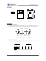
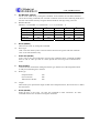
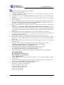
Board Layout
20mm
RS-232
RS-232
J1
EEPROM
J1
3.3V Tx Rx GND
28mm
OV Sensor
OV528
Top View
Bottom View
Figure 2 – C328
board layout and serial interface pin
Serial Interface
1.
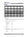
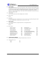
Single Byte Timing Diagram
A single byte RS-232 transmission consists of the start bit, 8-bit contents and the stop bit. A start
bit is always 0, while a stop bit is always 1. LSB is sent out first and is right after the start bit.
Single Byte Transmission
Stop
Bit 7
Bit 6
Bit 5
Bit 4
Bit 3
Bit 2
Bit 1
Bit 0
Start
Figure 3 – RS-232 single byte timing diagram
2.
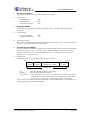
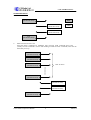
Command Timing Diagram
A single command consists of 6 continuous single byte RS-232 transmissions. The following is
an example of SYNC (AA0D00000000h) command.
SYNC Command
AAh
0Dh
00h
00h
00h
00h
Single
Byte
Figure 4 – RS-232 SYNC command timing diagram
C328 JPEG Compression Module
3
2004.8.19