1
The first real
innovation
in CPM in
a decade!
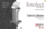
User Manual
OPTIFLEX®
TABLE OF CONTENTS
Precautionary Instructions . . . . . . . . . . . . . . . . . . . . . . . . . . . . . . . . . . . . . . . . . . 2
Foreword . . . . . . . . . . . . . . . . . . . . . . . . . . . . . . . . . . . . . . . . . . . . . . . . . . . . . . . 3
Product Description . . . . . . . . . . . . . . . . . . . . . . . . . . . . . . . . . . . . . . . . . . . . . . . 3
Package Contents . . . . . . . . . . . . . . . . . . . . . . . . . . . . . . . . . . . . . . . . . . . . . . . . 3
Installation . . . . . . . . . . . . . . . . . . . . . . . . . . . . . . . . . . . . . . . . . . . . . . . . . . . . . 4
Operation Instructions . . . . . . . . . . . . . . . . . . . . . . . . . . . . . . . . . . . . . . . . . . . . . 4
Quick Start . . . . . . . . . . . . . . . . . . . . . . . . . . . . . . . . . . . . . . . . . . . . . . . . . . . . . . 5
Pendant Functions . . . . . . . . . . . . . . . . . . . . . . . . . . . . . . . . . . . . . . . . . . . . . . . . 6
Other Pendant Functions . . . . . . . . . . . . . . . . . . . . . . . . . . . . . . . . . . . . . . . . . . 10
Pediatric Footplate Setup . . . . . . . . . . . . . . . . . . . . . . . . . . . . . . . . . . . . . . . . . . 11
User Maintenance . . . . . . . . . . . . . . . . . . . . . . . . . . . . . . . . . . . . . . . . . . . . . . . 11
Technical Maintenance . . . . . . . . . . . . . . . . . . . . . . . . . . . . . . . . . . . . . . . . . . . . 11
Technical Specifications . . . . . . . . . . . . . . . . . . . . . . . . . . . . . . . . . . . . . . . . . . . 12
Symbol Descriptions . . . . . . . . . . . . . . . . . . . . . . . . . . . . . . . . . . . . . . . . . . . . . 13
Troubleshooting . . . . . . . . . . . . . . . . . . . . . . . . . . . . . . . . . . . . . . . . . . . . . . . . . 14
Warranty . . . . . . . . . . . . . . . . . . . . . . . . . . . . . . . . . . . . . . . . . . . . . . . . . . . . . . 15
Parts Drawing . . . . . . . . . . . . . . . . . . . . . . . . . . . . . . . . . . . . . . . . . . . . . . . . . . 17
Parts List . . . . . . . . . . . . . . . . . . . . . . . . . . . . . . . . . . . . . . . . . . . . . . . . . . . . . . 18
PRECAUTIONARY INSTRUCTIONS
WARNING – The following precautions should be taken in
order to reduce the risk of fire, electrical shock, injury to persons
or damage to the OptiFlex®:
•
•
•
•
•
•
•
•
•
•
•
•
•
•
•
•
•
•
•
2
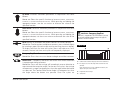
Read this manual before assembling or using OptiFlex.
Only use OptiFlex on solid, flat surfaces.
Extreme caution should be taken when in use around children.
Use OptiFlex only as described in this manual.
Keep hair, loose clothing, fingers and all parts of body away from
moving parts of OptiFlex.
DO NOT use OptiFlex outdoors or on wet surfaces.
Materials may become flammable or combustible if exposed to a
source of ignition.
Disconnect electrical supply before servicing or cleaning. Failure to
do so could result in electrical shock or personal injury.
DO NOT use OptiFlex while smoking or around open flame.
Exercise caution when using accessories and auxiliary devices such
as muscle stimulators, ColPaCs and other modalities.
Turn power off before unplugging.
Unplug the power supply by grasping the plug not the cord.
Damage may occur to OptiFlex if not transported and stored
between 0 and 140°F (-18 to 60°C).
Unplug from power supply when not in use.
DO NOT use if cord or plug is damaged.
Use extra care when touching metal of OptiFlex after exposure to
cold or heat.
DO NOT handle any electrical apparatus with wet hands.
DO NOT use OptiFlex as a toy.
Condensation could result and damage OptiFlex if unit is subjected to
periods of low temperatures followed by periods of high temperatures.
• DO NOT use on unstable surfaces or liquid filled devices such as
water mattresses or flotation pads.
• OptiFlex has been designed for maximum protection against the
exposure of urinary incontinence. Precautionary measures should still
be taken, though, when any type of liquid comes in contact with an
electrical apparatus.
• OptiFlex is made from high impact materials. However, structural
failure or hidden damage can be caused by shock, impact or dropping
the unit. Use care when transporting and storing unit to avoid
equipment damage.
• To isolate the unit from the power source, disconnect the power cord
at the wall outlet.
• OptiFlex should only be used after the operator has thoroughly read
and understands this manual.
• Rapid increases in ROM can cause complications.
• OptiFlex is not to be used in the presence of flammable anesthetic
mixture with air or with oxygen or nitrous oxide.
• Meets IEC/EN 60601-1-2 Electromagnetic Compatibility/interference
safety standard. (Care must be taken when operating this equipment
around other equipment. Potential electromagnetic or other
interference could occur to this or to the other equipment. Try to
minimize this interference by not using other equipment in
conjunction with it.)
OPTIFLEX USER MANUAL
FOREWORD
This manual has been written for the owners and operators of the OptiFlex®
continuous passive motion machine. It contains general instructions on operation,
precautionary practices, maintenance and parts information. In order to maximize use,
efficiency and the life of your OptiFlex, please read this manual thoroughly and
become familiar with the controls as well as the accessories before operating the
unit.
Specifications put forth in this manual were in effect at the time of publication.
However, owing to Chattanooga Group's policy of continual improvement, changes to
these specifications may be made at any time without obligation on the part of
Chattanooga Group, Inc.
PRODUCT DESCRIPTION
The OptiFlex is a continuous passive motion machine typically used postoperatively
on total knee replacement and Anterior Cruciate Ligament (ACL) repair patients. By
repeatedly flexing and extending the affected limb, the OptiFlex lessens the adverse
effects of immobilization and trauma on the joint.
OptiFlex is a prescription device used under the supervision or by the order of a
physician or other licensed healthcare provider.
PACKAGE CONTENTS
•
•
•
•
OptiFlex
Control Pendant
1 Package of Soft Goods
1 Operator's Manual
OPTIFLEX USER MANUAL
3
INSTALLATION
WARNING
• DO NOT plug in if switch is in ON position.
• DO NOT place leg in carriage until power is ON.
• If liquid or foreign object comes in contact with OptiFlex,
turn power switch OFF and have authorized personnel
check the unit.
CAUTION
• Obese patients can suffer chafing due to contact with
carriage frame.
• Failure to use securement strap correctly could change
anatomical alignment resulting in tissue damage or
joint injury.
• Unit must be placed on a solid, secure surface.
Otherwise, unit could tip causing hip to be dislocated.
OptiFlex® requires minimal installation. No lubrication is necessary and the unit is not
required to be sterile.
1. Place OptiFlex unit on a solid, flat surface.
2. Attach the Soft Goods to the carriage of the OptiFlex by using the instructions
provided with the Soft Goods.
3. Caution: Use only OptiFlex Soft Goods from the Chattanooga Group, Inc.
4. Plug the three-prong plug into a properly grounded wall outlet.
OPERATION INSTRUCTIONS
Setup and operation of the OptiFlex is quick and easy. However, the operation
instructions must be followed in order to ensure proper anatomical alignment and use
of OptiFlex.
1
3
2
4
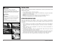
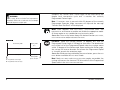
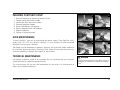
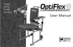
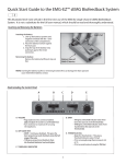
1. When setting up a new patient, activate RESET to clear the unit (see page 5).
Measure the patient from hip joint (greater trochanter) to knee in centimeters.
(Photo 1)
2. Adjust OptiFlex femur component to match hip to knee measurement in
centimeters. (Photo 2)
3. Carefully place OptiFlex under the affected limb. Align knee joint with the
corresponding hinge point on unit. (Photo 3)
4. Adjust the foot plate using the foot plate locking knobs so the patient's foot rests
comfortably and the patient kit supports the leg from knee to foot. (Photo 4)
5. Secure the limb in the carriage frame by fastening the strap. (Photo 5)
5
4
OPTIFLEX USER MANUAL
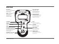
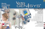
QUICK START
FAST BACK ™
Carriage will slow
down within 15° of
the flexion angle.
MODE
Used in conjunction
with Fast Back,
Oscillation Zone and
Progressive ROM.
EXTENSION
Adjusts the extension angle.
FLEXION
Adjusts the flexion angle.
SPEED
Adjusts the speed of operation.
EXTENSION / FLEXION DELAY
Allows user to program carriage
to stop at both the extension
and flexion angle for the
time programmed.
EMERGENCY STOP/START
Starts or Stop treatment
OPTIFLEX USER MANUAL
OSCILLATION ZONE ™
Carriage will oscillate
three times between the
flexion angle and 10° less
than the flexion angle.
PROGRESSIVE ROM ™
Unit will automatically increase
the programmed flexion angle
by 1° every hour up to a
maximum of 5° per day.
RESET
Clear previous treatment
settings and completed cycles.
UP ARROW
Allows user to increase
treatment parameters.
DOWN ARROW
Allows user to decrease
treatment parameters.
COMFORT ZONE ™
Temporarily decreases the
flexion ROM when discomfort
is experienced.
5
PENDANT FUNCTIONS
All user input and feedback is provided through the pendant. The following are
descriptions of each button provided with OptiFlex®.
Extension: View and modify the extension angle parameter.
How to use: To view the extension angle, press and hold the EXTENSION
button. To modify the current extension angle, press and hold the
EXTENSION button while pressing either the UP or DOWN ARROW.
Flexion: View and modify the flexion angle parameter.
How to use: To view the flexion angle, press and hold the FLEXION button.
To modify the current flexion angle, press and hold the FLEXION button
while pressing either the UP or DOWN ARROW.
Speed: View and modify the speed parameter.
How to use: To view the speed, press and hold the SPEED button. To
modify the current speed, press and hold the SPEED button while
pressing either the UP or DOWN ARROW.
Extension/Flexion Delay: View and modify the delay time for the
extension or flexion angles. Using EXTENSION/FLEXION DELAY will cause
the carriage to stop at the extension and flexion angle for the time
programmed.
How to use: To view the extension/flexion delay time, press and hold the
EXTENSION/FLEXION DELAY button. You can set independent DELAY times
for extension and flexion. If an extension and or flexion delay time is
required, simply hold down the DELAY button and the EXTENSION or
FLEXION button and use the UP or DOWN ARROWS to adjust the time.
6
OPTIFLEX USER MANUAL
Up Arrow: Increases treatment parameters in conjunction with other
buttons.
How to use: Select the specific function to increase (SPEED, EXTENSION,
FLEXION or EXTENSION/FLEXION DELAY). While pressing and holding the
appropriate button, use the UP ARROW to increase the value of the
specified function.
Down Arrow: Decreases treatment parameters in conjunction with other
buttons.
How to use: Select the specific function to increase (SPEED, EXTENSION,
FLEXION or EXTENSION/FLEXION DELAY). While pressing and holding the
appropriate button, use the DOWN ARROW to decrease the value of the
specified function.
Reset: Resets all parameter and patient counters to factory defaults.
How to Use: To reset patient compliance counters, press and hold lightly
by inserting a paper clip and accept reset by pressing the MODE button.
To display total unit run time and cycles, press and hold RESET for 3
seconds, the total unit time and cycles are temporarily displayed.
CAUTION – Emergency Stop/Start
When unit is stopped and STOP/START button is pressed,
the unit will immediately begin moving in the opposite
direction of the last movement.
COMFORT ZONE
Emergency Stop/Start: Starts or stops the treatment.
How to Use: Press the START/STOP button to begin or end the treatment.
Comfort Zone™: Temporarily decreases the flexion ROM when discomfort
is experienced during treatment.
How to Use: Press and the carriage will immediately reverse direction to
move toward the extension angle. For the next five cycles, the carriage
will operate in a range five degrees less than the angle where the button
was pressed. The Comfort Zone Flexion Angle is five degrees less than
the angle where the button was pressed. Once five cycles are
OPTIFLEX USER MANUAL
C = Comfort Zone activated temporary flexion limit established.
5° = Five degrees less than the angle where Comfort Zone was
activated.
Upon completion of five cycles, ROM will increase by one
degree each cycle until it reaches P.
P = Programmed Flexion angle.
S = Start/Finish.
7
WARNING
If pain is severe, do not use Comfort Zone. Stop treatment
immediately. Failure to do so could result in tissue damage
and could compromise surgical repair.
complete, the Comfort Zone™ Flexion Angle will be increased by one
degree each consecutive cycle until it reaches the currently
Programmed Flexion Angle.
Note: If COMFORT ZONE is pressed within 30 degrees of the currently
Programmed Extension Angle, treatment will stop and the message
"Comfort Zone Too Small" will be displayed.
Mode: Used together with FAST BACK ™, OSCILLATION ZONE ™ and
PROGRESSIVE ROM button to enable and disable the appropriate mode.
All three modes or any combination may be used at once.
How to Use: Press MODE button along with desired function (FAST BACK,
OSCILLATION ZONE and/or PROGRESSIVE ROM).
FAST BACK
Non-Working ROM
Working ROM
(10°)
Fast Speed
Slow Speed
Fast Speed
Fast Speed
Working ROM
Speed = 60°/min.
F = Programmed Flexion Angle
E = Programmed Extension Angle
8
Fast Back™: When the carriage reaches 15 degrees less than the
Programmed Flexion Angle, it will begin to slow down. The deceleration
rate will be half of the Programmed Speed when the carriage comes
within 10 degrees of the flexion angle. Upon reaching the flexion angle,
the carriage will reverse direction and resume the Programmed Speed
as it moves towards the extension angle.
How to Use: While pressing and holding the MODE button, press the FAST
BACK button to enable the FAST BACK mode
Note: If both FAST BACK and OSCILLATION ZONE modes are enabled, the
carriage will move at the slower of 75°/min and half of the Programmed
Speed while in the OSCILLATION ZONE ROM.
OPTIFLEX USER MANUAL
Oscillation Zone™: When the carriage reaches the Programmed Flexion
Angle, it will oscillate between the Programmed Flexion Angle and ten
degrees less than the flexion angle three times. The ten degree range
of motion is known as the OSCILLATION ZONE ROM. While in the
OSCILLATION ZONE ROM, the carriage will move at 75 deg/min or the
Programmed Speed, whichever is slower. On the third oscillation cycle,
the carriage will hold at the flexion angle for the Programmed
EXTENSION/FLEXION Delay Time.
How to Use: While pressing and holding the MODE button, press the
OSCILLATION ZONE button to enable the OSCILLATION ZONE mode.
Note: If both FAST BACK™ and OSCILLATION ZONE modes are enabled, the
carriage will move at the slower of 75 deg/min and half of the
Programmed Speed while in the OSCILLATION ZONE ROM.
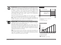
Progressive ROM™: When PROGRESSIVE ROM is activated, the unit will
automatically increase the Programmed Flexion Angle by one degree
every hour, up to a maximum of 5° per day.
How to Use: While pressing and holding the MODE button, press the
PROGRESSIVE ROM button to enable the PROGRESSIVE ROM mode. Set
the desired Final Flexion Angle by pressing and holding the FLEXION
Button while using the UP and DOWN Arrows. Accept the Final Flexion
Angle by pressing the MODE Button.
OSCILLATION ZONE
Non-Working ROM
Working ROM
(10°)
Carriage oscillates 3
times before holding on
the last cycle.
H = Optional Hold on Extension /Flexion Limit
* = Start / Finish
F = Programmed Flexion Angle
KNEE FLEXION ROM VS. TIME
5° Increase
per Day
Note: The unit must run for a full hour at the entire
ROM before the
flexion angle will be increased. The unit will not automatically increase
more than five degrees in any 24 hour period. Decreasing the flexion
angle will automatically deactivate this mode.
Day 1 Day 2 Day 3 Day 4 Day 5 Day 6 Day 7
I = Initial Knee Flexion ROM
F = Final Knee Flexion ROM
ROM = I + D(n- 1) x 5
where n is the number of days of therapy
OPTIFLEX USER MANUAL
9
OTHER PENDANT FUNCTIONS
Independent Delay Time
You can set independent DELAY times for extension and flexion. If an extension and
or flexion delay time is required, simply hold down the DELAY button and the
EXTENSION or FLEXION button and use the UP or DOWN ARROWS to adjust the time.
Selectable Scrolling
The scrolling feature is disabled at the factory. Should you desire to enable this
feature, simply press and hold the DELAY and MODE buttons. The display will scroll
patient data for two (2) cycles then return to displaying Current Carriage Angle.
Patient Lock-Out
The Patient Lock-Out feature prevents the patient from changing any parameter
except COMFORT ZONE™ and START/STOP.
To enable the Patient Lock-Out feature: Press and hold the UP ARROW and the MODE
button for three seconds. A single short beep will confirm that the feature has been
activated.
Repeating the above sequence will deactivate the feature. A single short beep will
confirm that the feature has been deactivated.
Language Selection
To select display language, press and hold the MODE and EXTENSION buttons
simultaneously for 3 seconds. Use and arrows to select desired language and then
press MODE to accept.
10
OPTIFLEX USER MANUAL
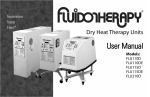
PEDIATRIC FOOTPLATE SETUP
1.
2.
3.
4.
5.
6.
7.
8.
Remove footplate by loosening footplate knob.
Tighten flexion adjustment knobs.
Loosen the tibial adjustment knobs.
Remove footplate support.
Rotate 180 degrees and replace.
Rotate footplate frame 180 degrees.
Replace footplate.
Tighten all adjusting knobs.
1
5
2, 3
6
4
7
USER MAINTENANCE
To clean OptiFlex®, turn unit off and unplug the power supply. Clean OptiFlex with a
damp cloth. DO NOT use abrasive cleaners. A small amount of mild household
detergent may be used, if desired.
Soft Goods may be laundered as required. However, the same Soft Goods should not
be used from patient to patient. Cleaning of Soft Goods will not meet the necessary
sanitation guidelines. Replace Soft Goods for each patient.
TECHNICAL MAINTENANCE
No attempt should be made to disassemble the unit. Maintenance and all repairs
should be made by authorized personnel only.
The manufacturer will not be held responsible for the results of maintenance or
repairs by unauthorized persons.
OPTIFLEX USER MANUAL
WARNING
Disconnect electrical supply from outlet before servicing or
cleaning the unit. Failure to do so could result in electrical
shock.
11
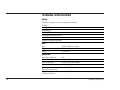
TECHNICAL SPECIFICATIONS
Safety
OptiFlex® complies with the following standards:
UL 2601-1
CAN/CSA 601.1
IEC/EN 60601-1
IEC/EN 60601-1-2
Meets MDD 93/42/EEC, CE 0413
Type “B” Equipment, Class I
Suitable for continuous operation
Unit
Input:
Weight:
Length:
120 VAC~50/60 Hz, 40 Watts
28 Lbs. (13 kg)
37 in. (94 cm)
Operation
Knee Flexion ROM Limit:
Knee Extension Limit:
Knee Speed Range :
Maximum Patient Weight:
Calf Length Range:
(knee joint to sole of foot)
Thigh Length Range:
(hip joint to knee joint)
12
120°
10° Hyper Extension
30°/min. to 150°/min. Nominal
350 Lbs. (159kg.)
10 to 23.5 in. (25.4 to 59.7 cm)
12 to 19 in. (30.5 to 48.3 cm)
OPTIFLEX USER MANUAL
Transportation and Storage
Unit should be transported and stored within the following conditions:
Temperature:
0 - 140°F (32° - 60°C)
Humidity:
0 - 75% Relative Humidity
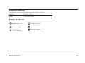
SYMBOL DEFINITION
Standby Power ON
Standby Power OFF
Emergency Stop
Start
Type B Equipment
Attention, Consult
Accompanying Documents
OPTIFLEX USER MANUAL
13
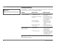
TROUBLESHOOTING
WARNING
Disconnect electrical supply from outlet before servicing or
cleaning the unit. Failure to do so could result in electrical
shock.
The following is a solutions guide to minor performance problems. Only qualified
personnel should service all other equipment problems.
PROBLEM
POSSIBLE CAUSE
POSSIBLE SOLUTION
OptiFlex® will not operate.
1. Unplugged at wall outlet.
1. Plug in and push ON/OFF
button to ON.
2. Push ON/OFF button to ON.
3. Once power returns, unit will
remain stopped until start
button is pressed.
4. Plug in pendant to unit.
5. Unplug unit and remove
obstruction from path of
carriage.
6. Adjust extension angle
smaller or flexion angle larger.
2. ON/OFF button not turned ON.
3. Power loss.
4. Pendant unplugged.
5. Carriage travel blocked.
6. Flexion angle set equal to
extension angle.
Treatment stopped in the
middle of operation.
1. Motor overcurrent.
2. Comfort Zone too small.
1. Press START/STOP button.
Carriage will move in
opposite direction.
2. Comfort Zone button can only
be used when ROM is greater
than 30 degrees of Programmed Extension Angle.
Note: Pendants of Optiflex® units model 2000 and 2020 will not function on Model
2030 and 2060 OptiFlex units.
14
OPTIFLEX USER MANUAL
WARRANTY
OptiFlex
Chattanooga Group, Inc. ("Company") warrants that the OptiFlex® ("Product") is free of
defects in material and workmanship. On the drive train components, including the
motor, gearbox, drive screw, drive nut, shaft couple and all drive bearings, this
warranty shall remain in effect for two (2) years. All other components shall be
warranted for the amount of one (1) year from the date of original consumer purchase
of this Product. This warranty extends to any owner of the Product during the
warranty period. If this Product fails to function during the warranty period because of
defect in material or workmanship, Company or the selling dealer will replace or repair
this Product without charge within a period of 30 days from the date on which the
defective Product is returned to the Company or the dealer. Company or the dealer
will ship the replacement or the repaired Product to the consumer's facility.
All repairs must be performed by a service center authorized by Chattanooga Group,
Inc. Any modifications or repairs performed by unauthorized centers or groups will
void this warranty. To participate in warranty coverage, this Product's warranty
registration card (included with Product) must be filled out and returned to
Chattanooga Group, Inc. by the original owner within ten (10) business days of
purchase.
Soft Goods Kit
Company warrants the Soft Goods Kit is free of defects in materials and
workmanship. This warranty shall remain in effect for thirty (30) days.
This Warranty Does Not Cover
1. Replacement parts or labor furnished by anyone other than the Company, the
dealer or an approved Company service agent.
2. Defects or damage caused by labor furnished by someone other than Company,
the dealer or an approved Company service agent.
OPTIFLEX USER MANUAL
15
3. Any malfunction or failure in the Product while it is in the possession of the
owner during the warranty period if the malfunction or failure is not caused by a
defect in material or workmanship, or if the malfunction or failure is caused by
unreasonable use, including the failure to provide reasonable and necessary
maintenance.
Company Shall Not Be Liable for Incidental or Consequential Damages to Property or Business
Some states do not allow the exclusion or limitation of incidental or consequential
damages, so the above limitation or exclusion may not apply to you.
TO OBTAIN SERVICE from Company or the selling dealer under this warranty, the
owner must do or abide by the following:
1. A written claim must be made within the warranty period to the Company or the
selling dealer. If the claim is made to the Company, written claim should be sent to:
4717 Adams Road
P.O. Box 489
Hixson, TN 37343 USA
Phone: 423-870-7200
2. The Product must be returned to the Company or the selling dealer by the owner.
This warranty gives you specific legal rights and you may also have other rights which
vary from state to state.
The Company does not authorize any person or representative to create for it any
other obligation or liability in connection with the sale of the Product. Any
representation or agreement not contained in the warranty shall be void and of no
effect.
16
OPTIFLEX USER MANUAL
PARTS DRAWING
OPTIFLEX USER MANUAL
17
PARTS LIST
18
OPTIFLEX USER MANUAL
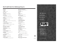
More Trusted Products from Chattanooga Group, Inc.
Achiever™
Supports
Adapta®
Treatment Tables
A.E.R. Boot ®
Auto Edema Reduction Boot
AirMedex™
Alternating Pressure Mattress
boo-boo pac™
Child Size Bear-Shaped Cold Pack
Cambion®
Shock Dampening Foot Care Products
Carpal-Trac™
Carpal Traction Accessory
ColPaC ®
Chilling Units and Reusable Cold Therapy Products
Conductor Gel™
Highly Conductive Ultrasound Gel
Contracture Products
Contracture Management Orthotic Products
CTS™
Carpal Tunnel Stretching Device
Dura-Stick™ Electrodes
Self-Adhesive Electrodes
EMG Retrainer®
Dual Channel Surface EMG
ErgoWave®
Intersegmental Traction Table
Flexi-Pac® I and II
Reusable Hot and Cold Compresses
Gel Medex™
Gel Mattress Overlay
Hydrocollator®
Heating Units and HotPacs™
Hydrogel®
Conductive Gelpad Dressings
Intelect ® Legend
Ultrasound and Electrotherapy Products
Measurement Instruments
Dynamometers, Goniometers, etc.
Myossage®
Massage Lotion
Nylatex®
The first real
innovation
in CPM in
a decade!
Elastic Wraps
Optiflex®
Continuous Passive Motion
PALS™Electrodes
Neurostimulation Electrodes
Para-Care ®
Paraffin Wax Unit
Pillow Perfect™
Cervical Pillow Line
Pivotal Therapy System™
Orthotics for the Spine
ProPower Pillow™
Power Massage Pillow
PresSsion®
Intermittent Compression
Pron Pillo ®
Positioning Pillow
Cervical Traction System
ISO 9001 CERTIFIED
Clinical Cervical Traction
SPORT-PAC™
4717 Adams Road
P.O. Box 489
Hixson, TN 37343 U.S.A.
1-423-870-2281
1-800-592-7329 U.S.A.
1-800-361-6661 CANADA
+ 423-870-7200 INTERNATIONAL
+ 423-870-2046 INTL. FAX
www.chattgroup.com
Soccer Ball Shaped Cold Pack
Therma-Wrap™
Hot and Cold Compression
Triton®
Treatment and Traction Equipment
TX®
Treatment and Traction Equipment
Vectra™ Series
Ultrasound and Electrotherapy products.
Wellness 1st™
Back Support
Women’s Contour Back Support
Back Support
J2021B
© 2000 Chattanooga Group, Inc.