1
®
Problem
Solving
Through
Innovation!
ISO 13485 CERTIFIED
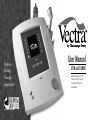
User Manual
STIM and COMBO
Electroluminescent LCD
Clinical Protocol System™
User Defined Protocols
Gel Warmer
Table of Contents
Foreword . . . . . . . . . . . . . . . . . . . . . . . . . . . . . . . . . . . . . . . . . . . . . . . . . . . . . . . . . . . . . . . . . . . . . . . . . . . . . . . . . .5
Product Description . . . . . . . . . . . . . . . . . . . . . . . . . . . . . . . . . . . . . . . . . . . . . . . . . . . . . . . . . . . . . . . . . . . . . . . . .5
Precautionary Instructions . . . . . . . . . . . . . . . . . . . . . . . . . . . . . . . . . . . . . . . . . . . . . . . . . . . . . . . . . . . . . . . . . . . .6
Installation . . . . . . . . . . . . . . . . . . . . . . . . . . . . . . . . . . . . . . . . . . . . . . . . . . . . . . . . . . . . . . . . . . . . . . . . . . . . . . . . .8
Package Contents . . . . . . . . . . . . . . . . . . . . . . . . . . . . . . . . . . . . . . . . . . . . . . . . . . . . . . . . . . . . . . . . . . . . . . . . . . .9
Indications, Contraindications and Adverse Effects for Electrical Stim . . . . . . . . . . . . . . . . . . . . . . . . . . . . . . . . .10
Hand Held Probes . . . . . . . . . . . . . . . . . . . . . . . . . . . . . . . . . . . . . . . . . . . . . . . . . . . . . . . . . . . . . . . . . . . . . . . . . .13
User Maintenance . . . . . . . . . . . . . . . . . . . . . . . . . . . . . . . . . . . . . . . . . . . . . . . . . . . . . . . . . . . . . . . . . . . . . . . . .14
Technical Maintenance . . . . . . . . . . . . . . . . . . . . . . . . . . . . . . . . . . . . . . . . . . . . . . . . . . . . . . . . . . . . . . . . . . . . . .14
Unit Orientation . . . . . . . . . . . . . . . . . . . . . . . . . . . . . . . . . . . . . . . . . . . . . . . . . . . . . . . . . . . . . . . . . . . . . . . . . . .15
Operator Interface . . . . . . . . . . . . . . . . . . . . . . . . . . . . . . . . . . . . . . . . . . . . . . . . . . . . . . . . . . . . . . . . . . . . . . . . . .17
Pain Management . . . . . . . . . . . . . . . . . . . . . . . . . . . . . . . . . . . . . . . . . . . . . . . . . . . . . . . . . . . . . . . . . . . . . . . . . .19
Interferential . . . . . . . . . . . . . . . . . . . . . . . . . . . . . . . . . . . . . . . . . . . . . . . . . . . . . . . . . . . . . . . . . . . . . . . . . . . . . .20
Premodulated . . . . . . . . . . . . . . . . . . . . . . . . . . . . . . . . . . . . . . . . . . . . . . . . . . . . . . . . . . . . . . . . . . . . . . . . . . . . .24
Microcurrent . . . . . . . . . . . . . . . . . . . . . . . . . . . . . . . . . . . . . . . . . . . . . . . . . . . . . . . . . . . . . . . . . . . . . . . . . . . . . .26
Muscle Contraction . . . . . . . . . . . . . . . . . . . . . . . . . . . . . . . . . . . . . . . . . . . . . . . . . . . . . . . . . . . . . . . . . . . . . . . . .27
High Volt . . . . . . . . . . . . . . . . . . . . . . . . . . . . . . . . . . . . . . . . . . . . . . . . . . . . . . . . . . . . . . . . . . . . . . . . . . . . . . . . .28
Russian . . . . . . . . . . . . . . . . . . . . . . . . . . . . . . . . . . . . . . . . . . . . . . . . . . . . . . . . . . . . . . . . . . . . . . . . . . . . . . . . . .29
VMS . . . . . . . . . . . . . . . . . . . . . . . . . . . . . . . . . . . . . . . . . . . . . . . . . . . . . . . . . . . . . . . . . . . . . . . . . . . . . . . . . . . .31
Ultrasound Indications and Contraindications . . . . . . . . . . . . . . . . . . . . . . . . . . . . . . . . . . . . . . . . . . . . . . . . . . . . .33
Ultrasound . . . . . . . . . . . . . . . . . . . . . . . . . . . . . . . . . . . . . . . . . . . . . . . . . . . . . . . . . . . . . . . . . . . . . . . . . . . . . . . .34
Combination Therapy . . . . . . . . . . . . . . . . . . . . . . . . . . . . . . . . . . . . . . . . . . . . . . . . . . . . . . . . . . . . . . . . . . . . . . .35
Vectra ® Utilities . . . . . . . . . . . . . . . . . . . . . . . . . . . . . . . . . . . . . . . . . . . . . . . . . . . . . . . . . . . . . . . . . . . . . . . . . . . .36
Technical Specifications . . . . . . . . . . . . . . . . . . . . . . . . . . . . . . . . . . . . . . . . . . . . . . . . . . . . . . . . . . . . . . . . . . . . .37
Warranty . . . . . . . . . . . . . . . . . . . . . . . . . . . . . . . . . . . . . . . . . . . . . . . . . . . . . . . . . . . . . . . . . . . . . . . . . . . . . . . . .41
Foreword
This manual has been written for the owners and operators of the Vectra ® 4C, Vectra ® 4S, Vectra ® 2C and Vectra ® 2S. It
contains general instructions on operation, precautionary practices, maintenance and parts information. In order to
maximize use, efficiency and the life of your unit, please read this manual thoroughly and become familiar with the
controls as well as the accessories before operating the unit.
Specifications put forth in this manual were in effect at the time of publication. However, owing to the Chattanooga
Group policy of continual improvement, changes to these specifications may be made at any time without obligation on
the part of Chattanooga Group.
Product Description
The Vectra ® Series offers a new dimension in electrotherapy, ultrasound and combination treatments. They offer seven
Pain Management and Muscle Contraction waveforms, Ultrasound and Combination therapy (4C, 2C only).
The Clinical Protocol System™ offers over 100 protocols. With user defined protocols, the clinician can create up to
9 unique electrotherapy and ultrasound protocols.
Vectra ® 4C, 2C and Vectra ® 4S, 2S are prescription devices used under the supervision or by the order of a physician or
other licensed healthcare provider.
©2004 Encore Medical Corporation or its affiliates, Austin, Texas, USA. Any use of editorial, pictorial or layout composition of this publication without
expressed written consent from the Chattanooga Group of Encore Medical, L.P. is strictly prohibited. This publication was written, illustrated and
prepared for print by the Chattanooga Group of Encore Medical, L.P.
VECTRA USER MANUAL – STIM AND COMBO
5
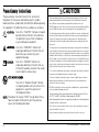
Precautionary Instructions
The precautionary instructions found in this section and
throughout this manual are indicated by specific symbols.
Understand these symbols and their definitions before operating
this equipment. The definition of these symbols are as follows;
!
=CAUTION-
!
=WARNING- Text with a “WARNING” indicator will
explain possible Safety infractions that will
potentially cause serious injury and
equipment damage.
!
=DANGER-
Text with a “CAUTION” indicator will explain
possible Safety infractions that could have
the potential to cause minor to moderate
injury or damage to equipment.
Text with a “DANGER” indicator will
explain possible Safety infractions that are
imminently hazardous situations that would
result in death or serious injury.
=EXPLOSION HAZARDText with an “Explosion Hazard” indicator
will explain possible safety infractions if this
equipment is used in the presence of
flammable anesthetics.
NOTE:- Throughout this manual “NOTE” may be found. These
Notes are helpful information to aid in the particular
area or function being described.
CAUTION
• Read, understand and practice the precautionary and operating instructions. Know the
limitations and hazards associated with using any electrical stimulation or ultrasound
device. Observe the precautionary and operational decals placed on the unit.
• DO NOT operate the Vectra ® when connected to any unit other than Chattanooga Group
devices. DO NOT operate the unit in an environment of short-wave diathermy use.
• The Ultrasound generator should be routinely checked before each use to determine that
all controls function normally, especially that the intensity control does properly adjust the
intensity of the ultrasonic power output in a stable manner. Also, determine that the
treatment time control does actually terminate ultrasonic power output when the timer
reaches zero.
• This unit generates, uses and can radiate radio frequency energy, and if not installed and
used in accordance with the instructions, may cause harmful interference to other devices
in the vicinity. However, there is no guarantee that interference will not occur in a particular
installation. Harmful interference to other devices can be determined by turning this unit on
and off or trying to correct the interference using one or more of the following: Reorient or
relocate the receiving device, increase the separation between the equipment, connect the
unit to an outlet on a different circuit from that to which the other device(s) are connected
and/or consult the factory field service technician for help.
• Use of controls or adjustments or performance of procedures other than those specified
herein may result in hazardous exposure to ultrasonic energy.
• This unit is not designed to prevent the ingress of water or liquids. Ingress of water or
liquids could cause malfunction of internal components of the system and therefore
create a risk of injury to the patient.
• DO NOT use sharp objects such as a pencil point or ballpoint pen to operate the buttons
on the control panel as damage may result.
• This unit should be operated, transported and stored in temperatures between 59° F and
104° F (15° C and 40° C), with Relative Humidity ranging from 30%-60%.
• Handle ultrasound applicator with care. Inappropriate handling of the ultrasound applicator
may adversely affect its characteristics.
• Before each use inspect treatment head for cracks, which may allow the ingress of
conductive fluid before each use.
• Inspect treatment head cables and associated connectors before each use.
6
VECTRA USER MANUAL – STIM AND COMBO
!
WARNING
• Federal law restricts this device to sale by, or on the
order of, a physician or licensed practitioner. This
device should be used only under the continued
supervision of a physician or licensed practitioner.
• Keep electrodes separated during treatment.
Electrodes in contact with each other could result in
improper stimulation or skin burns.
• Use of controls or adjustments or performance of
procedures other than those specified herein may r
esult in hazardous exposure to ltrasonic energy.
• For continued protection against fire hazard, replace
fuses only with ones of the same type and rating.
• Make certain that the unit is electrically referenced by
connecting only to a referenced electrical service
receptacle conforming to the applicable national and
local electrical codes.
• This device should be kept out of the reach of children.
• Care must be taken when operating this equipment
around other equipment. Potential electromagnetic or
other interference could occur to this or to the other
equipment. Try to minimize this interference by not
using other equipment in conjunction with it.
VECTRA USER MANUAL – STIM AND COMBO
DANGER
• Explosion hazard if Vectra ® is used in the presence
of flammable anesthetics mixture with air, oxygen,
or nitrous oxide. The warning symbol for this hazard
is prominently displayed on the cabinet.
• Patients with an implanted neurostimulation device
must not be treated with or be in close proximity to
any shortwave diathermy, microwave diathermy,
therapeutic ultrasound diathermy or laser diathermy
anywhere on their body. Energy from diathermy
(shortwave, microwave, ultrasound and laser) can be
transferred through the implanted neurostimulation
system, can cause tissue damage and can result in
severe injury or death. Injury, damage or death can
occur during diathermy therapy even if the implanted
neurostimulation system is turned "off."
Note: Before administering any treatment to a patient,
you should become acquainted with the operating
procedures for each mode of treatment available, as
well as the indications, contraindications, warnings and
precautions. Consult other resources for additional
information regarding the application of electrotherapy.
Dispose of all products in accordance with local and
national regulations and codes.
7
Installation
Initial Setup Instructions
Remove the Vectra ® 4C, Vectra ® 4S, Vectra ® 2C or Vectra ® 2S unit and any additional items ordered from the carton and
inspect for damage that may have occurred during shipment. Check the voltage rating on the serial decal located on the
bottom of the unit. Plug the system power supply in to a 100 Volt to 220-240 Volt AC outlet, as required.
CAUTION
• DO NOT attempt to use Direct Current (DC).
• DO NOT place unit in a location where the power cord could be tripped over or pulled out during treatment.
• DO NOT attempt to use the unit if it is not properly referenced.
8
VECTRA USER MANUAL – STIM AND COMBO
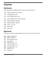
Package Contents
Standard Accessories
The following accessories are included with your Vectra ®, Vectra ® 4S, Vectra ® 2C and Vectra ® 2S:
78047
4248
12213
12214
72853
72852
10648
79542
79540
Applicator, Ultrasound 5 cm 2 (2C and 4C only)
Ultrasound Gel (2C and 4C only)
Lead, 120", Red/Black Channels 1 and 2
Lead, 120", Red/Black Channels 3 and 4 (4C and 4S only)
Electrodes, Carbonflex, 3" Round, Red
Electrodes, Carbonflex, 3" Round, Black
Nylatex, 21/2" x 24", Sewn
Operator's Manual
Patient Switch
Optional Accessories
The following is a list of optional accessories available for the Vectra ® 4C, Vectra ® 4S, Vectra ® 2C and Vectra ® 2S:
78046
78048
57007
79977
10832
10648
10828
79541
79571
Applicator, Ultrasound 10 cm 2
Applicator, Ultrasound 2 cm 2
Microcurrent Probe with Switch
High Volt Probe Kit
Strap, Nylatex, Long 21/2" x 48"
Strap, Nylatex, Medium, 21/2" x 24"
Strap, Nylatex, Short, 21/2" x 18"
Manual Stim Switch
Service Manual
VECTRA USER MANUAL – STIM AND COMBO
9
Indications/Contraindications Adverse Effects
for Electrical Stimulation
Interferential, Premodulated, Microcurrent
Indications
• Symptomatic relief of chronic, intractable pain. Management of pain associated with post-traumatic or
postoperative conditions.
Contraindications
• This device should not be used for symptomatic pain relief unless etiology is established or unless a pain syndrome
has been diagnosed. This device should not be used on patients with demand type cardiac pacemakers. This device
should not be used over cancerous lesions.
• Electrode placements must be avoided that apply current to the carotid sinus region (anterior neck) or transcereberally
(through the head).
Warnings
• The long-term effects of chronic electrical stimulation are unknown. Safety has not been established for the use of
therapeutic electrical stimulation during pregnancy.
• Adequate precautions should be taken when treating individuals with suspected or diagnosed heart problems,
or epilepsy.
• Benefits of Interferential stimulation have not been established for pain of central origin.
• This device is to be used as a symptomatic treatment for pain and has no curative value. Patients should be cautioned
and their activities regulated if pain is suppressed that would otherwise serve as a protective mechanism.
• Electronic monitoring equipment (such as ECG monitors and ECG alarms) may not operate properly when electrical
stimulation is being utilized.
10
VECTRA USER MANUAL – STIM AND COMBO
Precautions
• Isolated cases of skin rash may occur at the site of electrode placement following long-term applications. The irritation
may be reduced by use of an alternate conductive medium or an alternative electrode placement.
• Effectiveness of this treatment is dependent upon patient selection.
Adverse Effects
• Skin irritation and burns beneath the electrodes have been reported with the use of therapeutic electrical stimulation.
(VMS, RUSSIAN, HIGH VOLT only)
Indications
•
•
•
•
•
•
Relaxation of muscle spasms.
Prevention or retardation of disuse atrophy.
Increasing local blood circulation.
Muscle re-education.
Maintaining or increasing range of motion.
Immediate postsurgical stimulation of calf muscles to prevent venous thrombosis.
Contraindications
• This device should not be used on patients with demand type cardiac pacemakers.
• This device should not be used on cancer patients.
Warnings
• The long-term effects of chronic electrical stimulation are unknown.
• Safety has not been established for the use of therapeutic electrical stimulation during pregnancy.
• Adequate precautions should be taken when treating individuals with suspected or diagnosed heart problems.
VECTRA USER MANUAL – STIM AND COMBO
11
• Adequate precautions should be taken in the cases of persons with suspected or diagnosed epilepsy.
• DO NOT stimulate over the carotid sinus nerve, especially in persons with a known sensitivity to the carotid sinus reflex.
• Severe spasm of the laryngeal and pharyngeal muscles may occur if the electrodes are placed over the neck or mouth.
The contractions may be strong enough to cause breathing difficulty or even close the airway.
• Do not perform therapeutic electrical stimulation transcerebrally (through the head).
• Therapeutic electrical stimulation should not be applied over swollen, infected or inflamed areas of skin eruptions, (e.g.,
phlebitis, thrombophlebitis and varicose veins).
• Use extreme caution in transthoracic application of therapeutic electrical stimulation, introduction of electrical current
into the heart may cause arrhythmia.
• This device should only be used under medical supervision for adjunctive therapy for the treatment of medical diseases
and conditions.
• This device should be kept out of the reach of children.
Precautions should be observed in the presence of the following:
•
•
•
•
•
Following recent surgical procedures especially when muscle contractions could disrupt the healing process.
Where sensory nerve damage is present by a loss of normal skin sensation.
When there is a tendency to hemorrhage following acute trauma or fracture.
Over the menstruating uterus.
Some patients may experience skin irritation or hypersensitivity due to the electrical stimulation or the electrical
conductive medium. The irritations can usually be reduced by the use of an alternate conductive medium or alternative
electrode placement.
Adverse Effects
• Skin irritation and burns beneath the electrodes have been reported with the use of therapeutic electrical stimulation.
12
VECTRA USER MANUAL – STIM AND COMBO
HAND HELD PROBES (Optional)
Microcurrent Probes
Active/Treating Probe (with switch):
• Plug the Microcurrent probe (with switch) into the port marked Microcurrent Probe.
• To deliver Microcurrent to the patient, hold the active/treating probe as you would hold a pencil, press the button near
the tip of the probe to start delivery of current.
• You must also use a Reference Probe or a reference electrode as described below.
• The active/treating probe should touch the patient's skin at the treatment site and the reference probe should touch
the patient's skin elsewhere to complete the circuit.
• Once you press and release the button, current will be delivered for the treatment time, which has been set in the
Microcurrent parameter change screen. When the time has elapsed, a tone will sound and the device will return to
the GSR mode (default).
• The active/treating Microcurrent probe senses skin impedance levels when not delivering stimulation. This method of
skin impedance sensing is referred to as the GSR mode. When low levels of impedance are found, the number of
audible tones per second will increase.
Reference Probe:
• The purpose of the reference probe is to complete the circuit allowing flow of current through patient tissue.
The reference probe should touch the patient's skin away from the location of the active/treating probe.
• Attach the Black lead wire from channel one to the Reference Probe or you may use an electrode as a reference.
• Note: Place the reference device as close to the treatment site as possible where it will not interfere with placement of
the active/treating electrode; for example, do not place the reference electrode on the leg if you are treating the arm.
• Use the end of a (moistened) cotton swab inserted into the ends of both the active/treating probe and the reference
probe. The cotton must touch the probe's metal ring; use water to wet the cotton swab before starting the
treatment.
VECTRA USER MANUAL – STIM AND COMBO
13
HIGH VOLT Probe
The High Volt probe is used to deliver stimulation manually. Select the High Volt Waveform then simply plug the Red
lead wire (active/treating) into the connector of the Probe. The Black lead wire from the same channel should be
attached to an electrode and placed near the treatment site. The red lead wire is the active/treating probe and the black
lead wire (reference) is the reference probe or electrode.
• Select the parameters you wish to change then press the start button to begin treatment.
Note: Place the reference electrode as close to the treatment site as possible where it will not interfere with placement
of the active/treating electrode; for example, do not place the reference electrode on the leg if you are treating the arm.
User Maintenance
To clean, turn unit off and unplug the power supply. Clean the unit with a damp cloth. Do not use abrasive cleaners.
A small amount of mild household detergent may be used, if desired.
Between patient uses, patient applied parts should be wiped clean with a clean damp cloth, then use another clean cloth
to clean with a hospital grade germicide. Follow germicide manufacturer directions. Some highly concentrated
germicide mixtures could damage the product if not diluted in accordance with directions of the germicide manufacturer.
Technical Maintenance
No attempt should be made to disassemble the unit. Maintenance and all repairs should be made by authorized
personnel only. The manufacturer will not be held responsible for the results of maintenance or repairs by unauthorized
persons.
To fully maintain compliance with Federal Regulation Title 21 (21 CFR), this unit must be recalibrated annually. It is
recommended that all Chattanooga Group ultrasound products be returned to the factory or an authorized servicing
dealer for repairs or recalibration. It is also recommended after the replacement or repair of any major component.
14
VECTRA USER MANUAL – STIM AND COMBO
The following items should be checked at least monthly to ensure proper operation of this unit:
Power cord and plug: Check to make sure the cord is not frayed, kinked or does not have torn or cut insulation.
Sound head cable: Check to make sure the cable is flexible, free of kinks, not frayed and the insulation is intact.
Sound head face: Check to see that there is no build-up of gel or foreign material on the aluminum face.
Lead Wires: Check that the cables are not frayed, kinked or do not have torn or cut insulation.
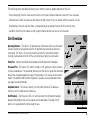
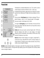
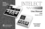
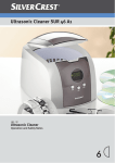
Unit Orientation
CONTRAST
Operating Channels – The Vectra ® 4C provides four channels of electrical stimulation
and one channel of ultrasound while the 4S provides four channels of electrical
stimulation. The Vectra ® 2C has two channels of electrical stimulation and one
channel of ultrasound while the 2S has two channels of electrical stimulation.
POWER ON LED
INTENSITY KNOB
ON
OFF
Probe Port – Connect the Microcurrent probe to the Microcurrent Probe port.
Ultrasound Port – The Vectra ® 4C and 2C include a 5 cm 2 applicator, which connects
to the ultrasound port. The advanced electronics of the Vectra ® reads the calibration
data of the ultrasound applicator every time you plug it in or access the ultrasound
mode. This sophisticated Electronic Signature ™ assures accurate calibration when
you apply ultrasound therapy.
REMOVABLE MEDIA
MICROCURRENT
PROBE PORT
STIMULATION OUTPUT CHANNELS
Amplitude Control – To increase intensity, turn the knob clockwise. To decrease
intensity, turn the knob counter clockwise.
On/Off Controls – The Power on LED will illuminate when the On button has been
pressed indicating that the unit has power and is operational. Pressing the Off
button will is powered off and not ready for use.
ULTRASOUND APPLICATOR
VECTRA USER MANUAL – STIM AND COMBO
15
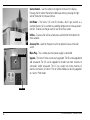
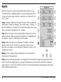
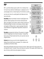
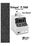
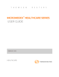
Contrast Controls – Use this button to change the contrast of the display.
Pressing the left side of the button to decrease contrast, pressing the right
side of the button to increase contrast.
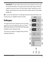
Gel Warmer – The Vectra ® (2C and 4C) includes a built in gel warmer as a
standard feature. Gel is warmed to a soothing temperature to increase patient
comfort. To deactivate the gel warmer, use the Utilities screen.
GEL WARMER
Utilities – To access the Utilities screen press and hold the Home button for
three seconds.
Accessory Port – Used for the patient switch or optional manual stimulation
switch.
ACCESSORY PORT
Mains Plug – This is where your main power supply is connected.
Upgrade – The Vectra ® Series can be easily upgraded. The 4S can be upgraded to
add ultrasound. The 2S can be upgraded to include two more channels of
stimulation and/or ultrasound. The 2C can accept two more channels of
electrical stimulation. All Vectra ® Stim or Combo models can be fully upgraded
to a Vectra ® Pro4 model.
MAINS PLUG
16
VECTRA USER MANUAL – STIM AND COMBO
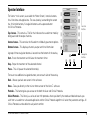
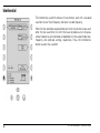
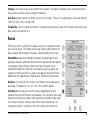
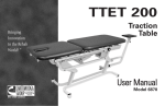
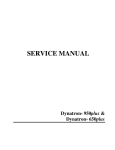
Operator Interface
The Vectra ® main screen, also called the "Home Screen," contains buttons
for all functions and applications. The area (overlay) surrounding the screen
has 10 function buttons, 5 navigation buttons and a separate button
for Clinical Protocols.
Function
Buttons
Top of screen – This contains a Title Bar that indicates the waveform or modality
being used and the output channels.
Center of screen – This contains the Waveform or Modality parameter options.
Bottom of screen – This displays channels, output and time information.
A group of three navigation buttons is located near the bottom of the overlay.
HOME
PROTOCOLS
Start – Starts the treatment and initiates the treatment timer.
Stop – Stops the treatment of the selected channel.
START
STOP
BACK
Navigation
Buttons
PAUSE
Pause – This will pause the selected channel(s).
There are two additional navigation buttons; one on each side of the overlay.
Back – Moves you back one screen in the software.
Home – Takes you directly to the main or home screen of the Vectra ® software.
Protocols – This button gives you access to the both the User and Clinical Protocols.
Clinical Protocols – This library is a series of over 100 protocols where you identify the needs and desired results you
wish from a waveform or ultrasound application and the Clinical Protocols algorithm will select the parameter settings. All
Clinical Protocols can be edited to suit patient comfort.
VECTRA USER MANUAL – STIM AND COMBO
17
User Protocols – This is a library that you create. You may store up to 24 protocols in the User Protocol library. To create a
User Protocol simply select a waveform, make the parameter changes, press the Protocols button and select User
Protocols. Your protocol will be saved in the first available slot.
Combination – This button (4C and 2C only) combines ultrasound therapy with Premodulated, High Volt, VMS or
Interferential waveforms.
Channel – The bottom section on the left side of the screen is reserved for channel display. The Vectra ® 4C will display
Channel 1, Channel 2, Channel 3, Channel 4 and Ultrasound. The Vectra ® 4S will display Channel 1, Channel 2, Channel 3
and Channel 4. The Vectra ® 2C will display Channel 1, Channel 2 and Ultrasound. The Vectra ® 2S will display Channel 1
and Channel 2.
When the individual channel displays the word Available, this indicates they are currently unused and available for use.
When you select a waveform the Vectra ® assigns the channel for you. As you select a waveform, the word Available in
the channel box will change to display the waveform you have selected.
The Channel Select button is used to select the channel you wish to view or modify.
Current Format – Constant Current (CC) or Constant Voltage (CV) output is available on Premod, VMS™, and Russian
current only. These waveforms are commonly used to elicit a muscle contraction and clinically one may wish for current
output to be in either format. High Volt and IFC are set on CV and Microcurrent on CC without the ability to change this
setting.
Constant Current (CC)- The output waveform maintains its set current amplitude level as prescribed by the clinician.
If resistance increases during a treatment, the unit will automatically increase the voltage to maintain the current
amplitude. The CC setting is commonly used when a goal of the selected waveform is to elicit a muscle
contraction. When CC is selected, the clinician needs to monitor the skin and be sure good electrode contact is
made throughout the course of therapy as any change in electrode contact or the conducting medium will cause
the voltage and current density to increase. Self-adhesive electrodes are recommended when CC is selected.
18
VECTRA USER MANUAL – STIM AND COMBO
Constant Voltage (CV)- If the output waveform encounters resistance, the set voltage remains the same, causing
the current amplitude to decrease. The CV setting is commonly used when a goal of therapy is traditional pain
management or sensory level stimulation. With Constant Voltage, as changes in electrode contact or levels of
impedance increase during the course of therapy, the output level can decrease, potentially limiting the desired
physiologic effect.
View – If you wish to view the parameters of an active/treating channel, press the channel selection button until the
channel you wish to view is highlighted, then press the view button.
Pain Management
The management of post-traumatic, post-operative or chronic intractable pain
associated with many areas of the body can be a difficult task. The Vectra ®
provides multiple waveforms and a Clinical Protocol Library to help you select
the appropriate waveform and parameter settings.
Three waveforms are available for Pain Management therapy; Interferential,
Premodulated and Microcurrent.
VECTRA USER MANUAL – STIM AND COMBO
19
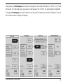
Interferential
The Interferential waveform consists of two channels, each with a sinusoidal
waveform; one of fixed frequency and one of variable frequency.
When the four electrodes are positioned so that the two channels cross each
other, the two waveforms mix within the tissue to produce a train of pulses
whose frequencies and amplitude are dependent on the sweep mode, beat
frequency and amplitude settings, respectively. Press the Interferential
button to select this waveform.
80-150 Hz
Volts CV Volts CV
Volts CV Volts CV
20
VECTRA USER MANUAL – STIM AND COMBO
When you press the Beat Frequency button, 5 options are displayed. They are 80-150 Hz (default), 1-150 Hz, 1-10 Hz, Fixed
and Variable. The Fixed option allows you to select a fixed frequency from 1-200 Hz. The selected option is highlighted.
To change the Fixed frequency, press the Fixed button, then press the Back button, press the Beat Fixed button, then use
the up or down arrows to change the frequency.
100 Hz
Volts CV Volts CV
Volts CV Volts CV
Volts CV Volts CV
Volts CV Volts CV
VECTRA USER MANUAL – STIM AND COMBO
Volts CV Volts CV
Volts CV Volts CV
Volts CV Volts CV
Volts CV Volts CV
21
The Variable option allows you to select a Low Beat frequency from 1-199 Hz and a High Beat frequency from 2-200 Hz.
To make changes in the Variable frequency, press the Variable button, the Back button, then Beat Low or High and select
the frequency of your choice.
Volts CV Volts CV
Volts CV Volts CV
22
Volts CV Volts CV
Volts CV Volts CV
Volts CV Volts CV
Volts CV Volts CV
Volts CV Volts CV
Volts CV Volts CV
VECTRA USER MANUAL – STIM AND COMBO
Beat Low describes the lowest frequency in the range of a sweep mode. For example when using a sweep of 80-150
Hz, 80 Hz is the lowest frequency. To change the Beat Low frequency press the Beat Low button then use the up or
down arrows to change the frequency.
Beat High describes the highest frequency in the range of a sweep mode. For example when using a sweep of 80-150
Hz, 150 Hz is the highest frequency. To change the Beat High frequency, press the Beat High button then use the up or
down arrows to change the frequency.
Balance controls the percent level of your set amplitude by channel. If you wish the patient to have a greater level of
stimulation intensity focused in a particular channel, press the button associated with that channel. A highlight bar will
indicate the change in amplitude and the output display will also reflect the change in amplitude.
Scan Percentage is the percentage of decrease from the maximum amplitude. Scan is amplitude modulation, expressed
as a percentage of the amplitude. The options available are 40% (default), 100% and Static (no scan). The rhythmical
varying of the amplitude of each channel produces the perceived movement of the Interferential field.
Treatment Time is the time allotted for treatment. To change the time parameter, press the Time button, then use the up
or down arrows to change the time.
Amplitude is displayed under the time display and when viewing a channel, on the lower left side of the screen.
Channel – The bottom section of the left side of the screen is reserved for channel display. The Vectra ® 4C will display
Channel 1, Channel 2, Channel 3, Channel 4 and Ultrasound. The 4S will display Channel 1, Channel 2, Channel 3 and
Channel 4. The Vectra ® 2C will display Channel 1, Channel 2 and Ultrasound. The 2S will display Channel 1 and Channel 2.
The individual channel displays have the word Available in them. This means they are currently unused and available for
use. When you select a waveform the Vectra ® assigns the channel for you. As you select a waveform, the word
Available in the channel box will change to the waveform you have selected.
Channel Select button is used to select the channel you wish to view or modify.
View – If you wish to view the parameters of an active/treating channel, press the channel selection button until the
channel you wish to view is highlighted, then press the view button.
VECTRA USER MANUAL – STIM AND COMBO
23
Premodulated
Premodulated is an amplitude modulated sine wave. This waveform is similar to
the beat frequency created by Interferential current. In some cases,
Premodulated therapy provides a good alternative for Interferential treatment
especially when treating areas of the body where four electrodes can not be
utilized.
When you press the Beat Frequency button, 5 options are displayed. They are
80-150 Hz (default), 1-150 Hz, 1-10 Hz, Fixed and Variable. The Fixed option
allows you to select a fixed frequency from 1-200 Hz.
Current Format
CV
To change the Fixed frequency, press the Fixed button, then press the Back
button, press the Beat Fixed button, button then use the up or down arrows to
change the frequency.
Volts CV
Volts CV
Variable option allows you to select a Low Beat frequency from 1-199 Hz and a
High Beat frequency from 2-200 Hz. To make changes in the Variable
frequency, press the Variable button, the Back button, then Beat Low or High
and select the frequency of your choice.
Beat Low describes the lowest frequency in the range of a sweep mode. For
example when using a sweep of 80-150 Hz, 80 Hz is the lowest frequency. To
change the Beat Low frequency, press the Beat Low button, then use the up
or down arrows to change the frequency.
Beat High describes the highest frequency in the range of a sweep mode. For example when using a sweep of 80-150 Hz,
150 Hz is the highest frequency. To change the Beat High frequency, press the Beat High button, then use the up or down
arrows to change the frequency.
24
VECTRA USER MANUAL – STIM AND COMBO
Cycle Time parameter controls the on/off cycle time of the current. There are 7 available options, Continuous (default),
10/50, 5/5, 10/10, 10/20, 4/12 and 10/30.
Treatment Time if the allotted time for treatment. To change the time parameter, press the Time button, then use the up or
down arrows to change the time.
Amplitude is displayed under the time display and when viewing a channel, on the lower left side of the screen.
Constant Format – Constant Current (CC) (Default) or Constant Voltage (CV) output is available on Premod, VMS™, and
Russian current only. These waveforms are commonly used to elicit a muscle contraction and clinically one may wish for
current output to be in either format. High Volt and IFC are set on CV and Microcurrent on CC without the ability to change
this setting. Refer to page 18 for more detail.
Channel – The bottom section of the left side of the screen is reserved for channel display. The Vectra ® 4C will display
Channel 1, Channel 2, Channel 3, Channel 4 and Ultrasound. The 4S will display Channel 1, Channel 2, Channel 3 and
Channel 4. The Vectra ® 2C will display Channel 1, Channel 2 and Ultrasound. The 2S will display Channel 1 and Channel
2.
The individual channel displays have the word Available in them. This means they are currently unused and available for
use. When you select a waveform the Vectra ® assigns the channel for you. As you select a waveform, the word Available
in the channel box will change to the waveform you have selected.
Channel Select button is used to select the channel you wish to view or modify.
View – If you wish to view the parameters of an active/treating channel, press the channel selection button until the channel you wish to view is highlighted, then press the view button.
VECTRA USER MANUAL – STIM AND COMBO
25
Microcurrent
Microcurrent is a monophasic rectangular wave with selectable or alternating
polarity. Many clinicians prefer microcurrent therapy because of the low
amperage utilized with selectable polarity.
For unattended therapy sessions, electrodes are usually placed on each side
of the affected area so treatment is administered "through" the affected area.
If attended, hands-on therapy is preferred, simply use the optional microcurrent
probe(s). Microcurrent is available through all channels on the 4S and 4C
and channels 1 & 2 on the 2S and 2C.
Method provides two options, Pads (default) and Probes. The Probes option
allows the use of the optional Microcurrent Probes.For more detail of microcurrent
probe set-up, refer to page 13.
Polarity of the Microcurrent waveform can be Positive (default), Negative or
Alternating. The Polarity of the active/treating electrode can be changed from
Positive (default) to Negative by pressing the Polarity button. When Positive
(default) polarity is selected, the Red leadwire is the positive polarity and the
Black leadwire is negative polarity. IF YOU SELECT NEGATIVE POLARITY, the
Red leadwire becomes negative polarity and the Black leadwire becomes positive
polarity. In the Alternating mode, the polarity alternates between positive and negative
every 2.5 seconds.
µA
µA
Frequency is the number of cycles delivered per second. The number of cycles per second is expressed in Hertz (Hz). The
range of frequency options is .1 to 1000.0 Hz. To change frequency, press the Frequency button then use the up or down
arrows to change the frequency. Frequency Tuning provides two options, Course and Fine. The Course tuning option
increases the frequency by 1Hz and the Fine tuning option increases by 1 tenth of 1 Hz.
26
VECTRA USER MANUAL – STIM AND COMBO
Muscle Contraction
Three waveforms are available for muscle contraction therapy; Twin-Peak
High Volt, Russian and VMS™. The appropriate selection of a waveform for
relaxing muscle spasms, increasing local circulation, re-educating muscles
that have been atrophied from disuse or injury, or to maintain or improve
joint range of motion can be difficult. Vectra ® provides multiple waveforms
to address these clinical problems and a Clinical Protocol mode that will
help direct you to the appropriate waveform and parameter setting as a
starting point.
VECTRA USER MANUAL – STIM AND COMBO
27
High Volt
1
High Volt stimulation has output ranges between 300 and 500 volts. True
Twin-Peak High Volt is designed to deliver very short-duration pulses, which
are very low in pulse charge. High Volt is available on all channels of the 4S,
4C, 2S, and 2C.
Sweep is frequency modulation of the High Volt current. When you press the
Sweep button, 4 options are displayed. They are 80-120 pps ,1-120 pps, 1-10
pps and Fixed (default at 100 pps) The Fixed (continuous) option allows you to
select a continuous fixed frequency from 1-120 pps.
Ramp controls the amount of time required to bring the stimulation up to the
selected amplitude. When you press the Ramp button it will toggle between
0.5 seconds, 1 second, 2 seconds (default) and 5 seconds.
Display provides two options of viewing output. The options are Voltage
(default) and Peak Current. The ability to assess peak current can help
determine tissue response, and an indication of impedance to current at the
electrode skin interface.
Method gives you the option of delivering High Volt to the patient either by
Pads (default) or Probe application.
Polarity of the active/treating electrode can be changed from Positive (default) to Negative by pressing the Polarity
button. When Positive (default) polarity is selected, the Red leadwire is positive polarity and the Black leadwire is
negative polarity. IF YOU SELECT NEGATIVE POLARITY, the Red leadwire becomes negative polarity and the Black
leadwire becomes positive polarity.
28
VECTRA USER MANUAL – STIM AND COMBO
Frequency is the number of pulses per second of the waveform. To change the Frequency, press the frequency button,
then use the up or down arrows to change the frequency.
Cycle Time parameter controls the on/off cycle time of the current. There are 7 available options, Continuous (default),
10/50, 5/5, 10/10, 10/20, 4/12 and 10/30.
Treatment Time is the time allotted for treatment. To change the time parameter, press the Time button, then use the up or
down arrows to change the time.
Russian
The Russian current is a 2,500 Hz sinusoidal carrier wave, interrupted to create
pulse trains or "bursts." The number of bursts per second is determined by the
burst frequency and the length of the bursts is determined by the duty cycle.
Channel Mode provides three methods of treatment including Single channel
application, Reciprocal application where stimulation alternates between agonists
and antagonists and Co-Contract where the timing of stimulation can be
coordinated through two channels to simultaneously co-contract agonist and
antagonist or differing sections of a larger muscle group. Pressing the Channel
Mode button will toggle between Single (default), Reciprocal and Co-Contract.
Duty Cycle is the ratio of on time to total time of the burst and is expressed as a
percentage. The options are 10%, 20%, 30%, 40% and 50% (default).
Set Intensity button allows you to set the intensity independently for each
individual channel or Both Channels simultaneously. This is important when using
Reciprocal and Co-Contract modes. When selecting the Reciprocal mode, adjust
the intensity for channel 1 (default), press the Set Intensity button and it will
change from channel 1 to channel 2, then set the intensity for channel two.
VECTRA USER MANUAL – STIM AND COMBO
Current Format
CC
CC
CC
29
The last option is Both Channels, which allows the intensity of both channels to be adjusted simultaneously.
Cycle Time parameter controls the on/off cycle time of the current. There are 7 available options, Continuous (default),
10/50, 5/5, 10/10, 10/20, 4/12 and 10/30.
Burst Frequency is the number of bursts per second (bps) and the available range is 1 bps to 200 bps.
Ramp controls the amount of time required to bring the stimulation up to the selected amplitude. When you press the
Ramp button it will toggle between .5 seconds, 1 second, 2 seconds (default) and 5 seconds.
Treatment Time is the time allotted for treatment. To change the time parameter, press the Time button, then use the up or
down arrows to change the time.
Constant Format – Constant Current (CC) (Default) or Constant Voltage (CV) output is available on Premod, VMS™, and
Russian current only. These waveforms are commonly used to elicit a muscle contraction and clinically one may wish for
current output to be in either format. High Volt and IFC are set on CV and Microcurrent on CC without the ability to change
this setting. For more detail, please refer to page 18.
30
VECTRA USER MANUAL – STIM AND COMBO
VMS™
1
VMS is a symmetrical biphasic square waveform with an inter-phase interval
that treats the tissue under each electrode equally. Its single pulses have the
same physiologic function as the beat frequency of the Interferential waveform.
Low total current makes this waveform good for comfortable sub-maximal
muscle contractions.
Channel Mode provides three methods of treatment including Single channel
application, Reciprocal application where stimulation alternates between
agonists and antagonists and Co-Contract where the timing of stimulation can
be coordinated through two channels to simultaneously co-contract agonist
and antagonist or differing sections of a larger muscle group. Pressing the
Channel Mode button will toggle between Single (default), Reciprocal and
Co-Contract.
Phase Duration is adjustable from 20-300 usec. Phase duration is the elapsed
time from the beginning to the termination of one phase. To change Phase
Duration, press the Phase Duration button then use the up or down arrows to
change the duration.
Current Format
CC
CC
CC
Set Intensity button allows you to set the intensity independently for each
individual channel or Both Channels simultaneously. This is important when
using Reciprocal and Co-Contract modes.
When selecting the Reciprocal mode, adjust the intensity for channel 1 (default), press the Set Intensity button and it
will change from channel 1 to channel 2, then set the intensity for channel two. The last option is Both Channels, which
allows the intensity of both channels to be adjusted simultaneously.
VECTRA USER MANUAL – STIM AND COMBO
31
Cycle Time parameter controls the on/off cycle time of the current. There are 7 available options, Continuous (default),
10/50, 5/5, 10/10, 10/20, 4/12 and 10/30. Frequency is the number of pulses per second (pps) and the available range is
10 pps to 120 pps.
Ramp controls the amount of time required to bring the stimulation up to the selected amplitude. When you press the
Ramp button it will toggle between .5 seconds, 1 second, 2 seconds (default) and 5 seconds.
Treatment Time is the time allotted for treatment. To change the time parameter, press the Time button, then use the up or
down arrows to change the time.
Constant Format – Constant Current (CC) (Default) or Constant Voltage (CV) output is available on Premod, VMS™, and
Russian current only. These waveforms are commonly used to elicit a muscle contraction and clinically one may wish for
current output to be in either format. High Volt and IFC are set on CV and Microcurrent on CC without the ability to change
this setting. Refer to page 18 for more detail.
32
VECTRA USER MANUAL – STIM AND COMBO
Ultrasound Indications and Contraindications
Indications
Ultrasound for use in applying deep heat can be used for treatment of selected medical conditions such as the relief of pain,
muscle spasms and joint contractures. These conditions may be associated with adhesive capsulitis, bursitis with slight
calcification, myositis and soft tissue injuries. The Vectra ® can provide therapeutic deep heating between 40 and 45° C in
all of its operating modes, while using any of the applicators available for this device.
Contraindications
•
•
•
•
•
•
•
•
•
•
•
•
An area of the body where a malignancy is known to be present.
The eyes.
The reproductive organs.
An acute infection or sepsis.
A pregnant uterus.
Deep vein thrombosis.
An arterial disease.
An anesthetized area or condition that causes impairment of sensation, such as chemotherapy.
The epiphyses of skeletally immature children.
The thoracic area if the patient is using a cardiac pacemaker.
A healing fracture.
Ischemic tissues in individuals with vascular disease where the blood supply would be unable to follow the increase in
metabolic demand and tissue necrosis might result.
• Patients with an implanted neurostimulation device must not be treated with or be in close proximity to any shortwave
diathermy, microwave diathermy, therapeutic ultrasound diathermy or laser diathermy anywhere on their body. Energy
from diathermy (shortwave, microwave, ultrasound and laser) can be transferred through the implanted
neurostimulation system, can cause tissue damage and can result in severe injury or death. Injury, damage or death can
occur during diathermy therapy even if the implanted neurostimulation system is turned "off."
VECTRA USER MANUAL – STIM AND COMBO
33
Ultrasound
Ultrasound is a form of mechanical energy that consists of high frequency
vibrations delivered to the body by means of an ultrasound beam emitted out
of an applicator. These high frequency vibrations pass through the tissues of
the body and are gradually absorbed and transformed into heat.
Continuous
This temperature increase triggers biological changes to occur in tissues for the
relief of pain, relaxation of muscle spasms and reduction of joint contractures.
The ultrasound frequency, duty cycle and level of intensity can all be adjusted
to produce the desired therapeutic effect.
Head Warming is a unique feature of the Vectra ® 4C and 2C that allows the
aluminum surface of the Ultrasound applicator to warm up to room
temperature, enhancing patient comfort.
Frequency of Ultrasound determines the depth of penetration. One megahertz
penetrates approximately 5 centimeters, and 3 megahertz penetrates to 2
centimeters. Both 1 and 3.3 MHz frequencies are available and can be changed
throughout the course of treatment by pressing the Frequency button.
Duty Cycle is the ratio of on time to total time of the ultrasound and is expressed
as a percentage. The options are 10%, 20%, 50% and 100% (Continuousdefault).
Display shows ultrasound output in Watts, or Watts Per Centimeter Squared.
Treatment Time is the allotted time for treatment. To change the time parameter, press the Time button, then use the up or
down arrows to change the time.
34
VECTRA USER MANUAL – STIM AND COMBO
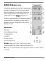
Combination Therapy (Models 4C and 2C Only)
In the Combination mode (available only on the 4C and 2C), ultrasound therapy
is combined with Premodulated, High Volt, VMS or Interferential waveforms
to generate a therapeutic effect. In this mode of therapy the aluminum face
of the ultrasound applicator becomes one half of the electrical circuit. An
electrode attached to the Channel 2 Red lead wire completes the circuit.
The benefits of ultrasound as expressed in the ultrasound section are coupled
with electrical stimulation; a typical application of combination therapy is for
the reduction of muscle spasm. Combination mode is limited to Channel 2 of
both the Vectra ® 4C and 2C.
Step-By-Step Instructions
•
•
•
•
•
•
Select Combo
Make any desired parameter changes
Set ultrasound intensity
Select Edit Stim
Set Stimulation intensity
Press Start to begin treatment
Head Warming is a unique feature of the Vectra ® that allows the aluminum surface
of the Ultrasound applicator to warm up to room temperature, enhancing patient comfort.
Stim button allows the selection of Premodulated (default), High Volt, VMS or Interferential waveforms for combination
with ultrasound.
VECTRA USER MANUAL – STIM AND COMBO
35
Edit Stim button allows you to modify the selected waveform's parameters. After selecting the Edit Stim screen, an Edit
US button appears, allowing you to modify the ultrasound parameters.
Frequency of Ultrasound determines the depth of penetration. One megahertz penetrates approximately 5 centimeters,
and 3 megahertz penetrates to 2 centimeters. Both 1 and 3.3 MHz frequencies are available and can be changed
throughout the course of treatment by pressing the Frequency button.
Duty Cycle is the ratio of on time to total time of the ultrasound and is expressed as a percentage. The options are 10%,
20%, 50% and 100% (Continuous-default).
Display shows ultrasound output in Watts or W/cm 2 .
Treatment Time is the allotted time for treatment. To change the time parameter, press the Time button, then use the up or
down arrows to change the time.
Vectra Utilities
To access the Utilities screen, press and hold the Home button for three seconds. After making selections, press the
Home button to return to the Home screen.
The Language option allows you to select the desired language that is displayed on the Vectra ® screen. Supported
languages include English, Spanish and French.
The Gel Warmer turns the Gel Warmer feature on or off (2C and 4C only).
36
VECTRA USER MANUAL – STIM AND COMBO
Technical Specifications
Vectra Unit
Dimensions:
Weight:
Power:
Fuse:
Electrical Class:
Electrical TYPE:
16"W x 21 ½"D x 8"H (40.6 cm W x 54.6 cm D x 20.3 cm H)
13 lbs. (5.9 kg)
Input: 100-240V~, 1.0A, 50/60 Hz
1.0A TIME LAG
CLASS I
TYPE BF
ATTENTION: Consult Accompanying Documents.
Suitable for continuous operation.
Ordinary equipment as far as harmful ingress of water.
VECTRA USER MANUAL – STIM AND COMBO
37
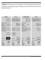
Stimulator Output Parameters
Parameter
Function
Carrier Frequency
Beat Frequency
Scan Mode
Scan Time
Sweep Time
Duty Cycle
Ramp Up / Ramp Down
Cycle Time
Alternating Time in Seconds
Polarity
Amplitude (CC)
Voltage (max) (CV)
Treatment Time
Interferential
Electrodes
5000 Hz
0-200 Hz
On/Off
15 sec
15 sec
N/A
N/A
N/A
N/A
N/A
N/A
200 Volts
1 to 60 min
Premodulated
Electrodes
5000 Hz
0-200 Hz
N/A
N/A
15 sec
N/A
N/A
5/5, 10/10, 10/20, 4/12, 10/30, 10/50 Continuous
N/A
N/A
0-50 mA RMS
200 Volts
1 to 60 min
Microcurrent
Electrodes, Probes
N/A
0.1-1000 Hz
N/A
N/A
N/A
N/A
1 sec ±
N/A
2.5 sec
+,-, ±
10-1000 uA
N/A
1 to 60 min
N/A = Not Applicable
38
VECTRA USER MANUAL – STIM AND COMBO
Stimulator Output Parameters
Parameter
Function Mode
Voltage (max) (CV)
Treatment Time
Russian
Electrodes
Single, Recipr.
Co-Contraction
2500 Hz
N/A
20-100 Hz
N/A
N/A
10-50%
.5, 1, 2, 5 sec
5/5,10/10, 10/20
4/12, 10/30, 10/50
Continuous
N/A
0-100 mA RMS
into 500 ohm load
200 Volts
0-60 min
N/A = Not Applicable
*4S and 4C only
Carrier Frequency
Pulse Frequency
Burst Frequency
Phase Duration
Interphase Interval
Duty Cycle
Ramp Up / Ramp Down
Cycle Time
Polarity
Amplitude (CC)
VECTRA USER MANUAL – STIM AND COMBO
High Volt
Electrodes, Probes
Single, Recipr.*
Co-Contraction*
N/A
10-120 pps
N/A
N/A
N/A
N/A
N/A
5/5,10/10, 10/20
4/12, 10/30, 10/50
Continuous
Pos. (+), Neg. (-)
N/A
0-500 Volts
0-60 min
VMS
Electrodes, Probes
Single, Recip.
Co-Contraction
N/A
5-200 pps
N/A
20-300 microseconds
100 microseconds
N/A
.5, 1, 2, 5 sec
5/5,10/10, 10/20
4/12, 10/30, 10/50
Continuous
N/A
0-200 mA Peak
into 500 ohm load
200 Volts, Peak to Peak
0-60 min
39
Ultrasound
Channel
Frequency
Duty Cycle
Pulse Duration
US (ultrasound)
1 MHz ± 5% & 3.3 MHz ± 5%
100% (continuous mode) 50%, 20%, 10% (pulsed mode)
5 msec ± 20% (50% duty cycle, pulsed mode)
2 msec ± 20% (20% duty cycle, pulsed mode)
Ultrasonic Power
Variable from 1-20 watts, 10 cm 2 crystal
Variable from 0.4-10 watts, 5 cm 2 crystal
Variable from 0.2-4 watts, 2 cm 2 crystal
Output Meter Accuracy ±20% for any output above 10% of maximum
Temporal Peak/Average 2:1 ± 20% for 50% duty cycle
Intensity Ratio
5:1 ± 20% for 20% duty cycle
9:1 ± 20% for 10% duty cycle
Output
Continuous: 1 MHz or 3.3 MHz nominal signal that is activated
as long as the timer is operating.
Pulsed:
1 MHz or 3 MHz signal, modulated 100% by the
100 Hz rectangular wave with the selected duty cycle.
Timer Accuracy
±0.2 minute
Sound Head
Effective Radiating Area: 8.5 cm 2 ± 1.5 cm 2 for the 10 cm 2 crystal
4.0 cm 2 ± 1.0 cm 2 for the 5 cm 2 crystal
1.8 cm 2 -0.4/+0.2 cm 2 for the 2 cm 2 crystal
Maximum Beam
5.0:1 Max
Non-uniformity Ratio
Beam Type
Collimating
40
VECTRA USER MANUAL – STIM AND COMBO
Warranty
Chattanooga Group ("Company") warrants that the Vectra ® 4C, 4S, 2C and 2S ("Product") excluding accessories are free of
defects in material and workmanship. This warranty shall remain in effect for two (2) years from the date of original
consumer purchase of this Product and extends to any owner of the Product during the warranty period. Accessories that
are included as standard with the product (as listed in the users manual) are warranted for 90 days. Ultrasound
applicators (2 cm 2, 5 cm 2 or 10 cm 2) as included with the Combo (Combination) units are warranted for one (1) year. If
this Product fails to function during the warranty period because of defect in material or workmanship, Company or the
selling dealer will replace or repair this Product without charge within a period of 30 days from the date on which the
defective Product is returned to the Company or the dealer. Company or the dealer will ship the replacement or the
repaired Product to the consumer's facility.
All repairs must be performed by a service center authorized by Chattanooga Group. Any modifications or repairs
performed by unauthorized centers or groups will void this warranty. To participate in warranty coverage, the warranty
registration card (included with Product) must be filled out and returned to Chattanooga Group by the original owner
within ten business days of purchase.
This Warranty Does Not Cover
1. Replacement parts or labor furnished by anyone other than the Company, the dealer or an approved Company
service agent.
2. Defects or damage caused by labor furnished by someone other than Company, the dealer or an approved Company
service agent.
3. Any malfunction or failure in the Product while it is in the possession of the owner during the warranty period if the
malfunction or failure is not caused by a defect in material or workmanship, or if the malfunction or failure is caused
by unreasonable use, including the failure to provide reasonable and necessary maintenance.
VECTRA USER MANUAL – STIM AND COMBO
41
Company Shall Not Be Liable for Incidental or Consequential Damages to Property or Business
Some states do not allow the exclusion or limitation of incidental or consequential damages, so the above limitation or
exclusion may not apply to you.
TO OBTAIN SERVICE from Company or the selling dealer under this warranty, the owner must do or abide by the following:
1. A written claim must be made within the warranty period to the Company or the selling dealer. If the claim is made
to the Company, written claim should be sent to:
4717 Adams Road
P.O. Box 489
Hixson, TN 37343
Phone: (800) 592-7329
Outside US: +1 (423) 870-2281
Fax: (423) 875-5497
2. The Product must be returned to the Company or the selling dealer by the owner.
This warranty gives you specific legal rights and you may also have other rights which vary from state to state.
The Company does not authorize any person or representative to create for it any other obligation or liability in connection
with the sale of the Product. Any representation or agreement not contained in the warranty shall be void and of no effect.
42
VECTRA USER MANUAL – STIM AND COMBO
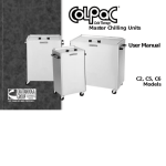
More Trusted Products from Chattanooga Group
Achiever™
Supports
Adapta®
Treatment Tables
A.E.R. Boot ®
Auto Edema Reduction Boot
Cambion®
Shock Dampening Foot Care Products
Carpal-Trac™
Carpal Traction Accessory
ColPaC ®
Chilling Units and Reusable Cold Therapy Products
Conductor Gel™
Highly Conductive Ultrasound Gel
Contracture Products
Contracture Management Orthotic Products
CTS™
Carpal Tunnel Stretching Device
DURA-STICK™ Electrodes
Self-Adhesive Electrodes
EMG Retrainer™ EMG Retrainer™ IR
Dual Channel Surface EMG
Flexi-Pac® I and II
Reusable Hot and Cold Compresses
Gel Medex™
Gel Mattress Overlay
Hydrocollator®
Heating Units and HotPacs™
Intelect ® Legend
Ultrasound and Electrotherapy Products
Measurement Instruments
Dynamometers, Goniometers, etc.
Myossage®
Massage Lotion
Nylatex®
Elastic Wraps
OptiFlex™ & OptiFlex® S
Continuous Passive Motion
Opti-Ice™
Cold Therapy System
Para-Care™
Paraffin Wax Unit
Pillow Perfect™
Problem
Solving
Through
Innovation!
Cervical Pillow Line
Pivotal Therapy System™
Orthotics for the Spine
ProPower Pillow™
Power Massage Pillow
PresSsion®
Intermittent Compression
Pron Pillo ®
Positioning Pillow
SensaFlex™
Hot and Cold Compress
SPORT-PAC™
Soccer Ball Shaped Cold Pack
Theratherm™
Digital Moist Heating Pad
Therma-Wrap™
Hot and Cold Compression
Triton®
ISO 13485 CERTIFIED
Treatment and Traction Equipment
TX®
4717 Adams Road
P.O. Box 489
Hixson, TN 37343 U.S.A.
1-423-870-2281
1-800-592-7329 U.S.A.
1-800-361-6661 CANADA
+1 423-870-2046 OUTSIDE U.S.A. FAX
www.chattgroup.com
Treatment and Traction Equipment
Vectra ®™ Series
Ultrasound and Electrotherapy products
Versa Bath Seat™
Aid to Daily Living
Wellness 1st™
Back Support
Women’s Contour Back Support
Back Support
79542F
© 2004 Encore Medical