1
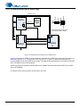
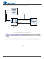
3.1.11.2 Clock and Data Flow for S/PDIF Input
MUXED_DSP_LRCLK1
J101
MUXED_MCLK
\ON_BRD1
HDR1
PLL
Use these jumper settings for the clocking
mode and inputs shown in diagram.
XTAL_OUT
DSP_DAI4
HDR2
\SPDIF
SPDIF
Input
J100
S/PDIF Input
12CH_ADC
CS8416
\ON_BRD2
MUXED_DSP_SCLK1
SDOUT
DAI
DAO
DSP_SCLK
SDIN
DSP_LRCLK
DSP_DA0[3:0]
CS485XX
CS42448
CS42448
2x
2x
XMTA SPDIF OUT
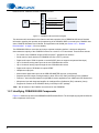
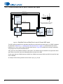
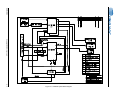
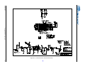
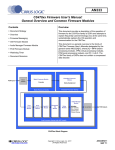
Figure 3-3. Simplified Clock and Data Flow for S/PDIF Input
Figure 3-3 illustrates the S/PDIF clocking architecture used when any S/PDIF RX is used as an audio source, as
described in Section 4.2.2, “Changing the Audio Input Source” on page 4-3). MCLK recovered from the
incoming S/PDIF stream is the MCLK for the system. The CS8416 also generates SCLK and LRCLK for the DAI
side of the DSP from the recovered MCLK.
On the output side, the CS485XX slaves to MCLK from CS8416 and masters SCLK and LRCLK for the DAC
side of the CS42448.
An example of this clocking scheme can be found in pcm.cpa.
7