1
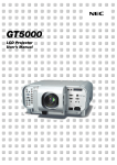
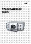
Liquid Crystal Projector
Model 9060
USER'S MANUAL
Important Information
Precautions
RF Interference
Please read this manual carefully before using your 9060 Projector.
And keep this manual handy for future reference.
WARNING
The Federal Communications Commission does not allow any
modifications or changes to the unit EXCEPT those specified by
NEC Solutions, Inc. in this manual. Failure to comply with this
government regulation could void your right to operate this equipment.
This equipment has been tested and found to comply with the
limits for a Class B digital device, pursuant to Part 15 of the FCC
Rules. These limits are designed to provide reasonable protection against harmful interference in a residential installation. This
equipment generates, uses, and can radiate radio frequency
energy and, if not installed and used in accordance with the instructions, may cause harmful interference to radio communications. However, there is no guarantee that interference will not
occur in a particular installation. If this equipment does cause
harmful interference to radio or television reception, which can
be determined by turning the equipment off and on, the user is
encouraged to try to correct the interference by one or more of
the following measures:
Your serial number is located on the bottom of your 9060.
Record it here:
CAUTION
To turn off main power, be sure to remove the plug
from power outlet.
The power outlet socket should be installed as near
to the equipment as possible, and should be easily
accessible.
CAUTION
TO PREVENT SHOCK, DO NOT OPEN THE CABINET.
NO USER-SERVICEABLE PARTS INSIDE.
REFER SERVICING TO QUALIFIED NEC SERVICE PERSONNEL.
• Reorient or relocate the receiving antenna.
This symbol warns the user that uninsulated voltage within the unit may be sufficient to cause electrical shock. Therefore, it is dangerous to make any
kind of contact with any part inside of the unit.
• Increase the separation between the equipment and receiver.
• Connect the equipment into an outlet on a circuit different from that to
which the receiver is connected.
• Consult the dealer or an experienced radio / TV technician for help.
This symbol alerts the user that important information concerning the operation and maintenance of
this unit has been provided. The information should
be read carefully to avoid problems.
Important Safeguards
These safety instructions are to ensure the long life of your projector
and to prevent fire and shock. Please read them carefully and heed
all warnings.
WARNING
Installation
TO PREVENT FIRE OR SHOCK, DO NOT EXPOSE THIS UNIT
TO RAIN OR MOISTURE.
DO NOT USE THIS UNIT’S GROUNDED PLUG WITH AN EXTENSION CORD OR IN AN OUTLET UNLESS ALL THREE
PRONGS CAN BE FULLY INSERTED.
DO NOT OPEN THE CABINET. THERE ARE HIGH-VOLTAGE
COMPONENTS INSIDE. ALL SERVICING MUST BE DONE BY
QUALIFIED NEC SERVICE PERSONNEL.
1. For best results, use your projector in a darkened room.
DOC Compliance Notice
5. Handle your projector carefully. Do not hold the lens hood and the
terminal covers. Dropping or jarring can damage internal components.
2. Place the projector on a flat, level surface in a dry area away from
dust and moisture. Tilting the front of the projector up or down by
more than 45° from level could reduce lamp life by up to 20%.
3. Do not place your projector in direct sunlight, near heaters or heat
radiating appliances.
4. Exposure to direct sunlight, smoke or steam can harm internal
components.
This Class B digital apparatus meets all requirements of the Canadian Interference-Causing Equipment Regulations.
6. Do not place heavy objects on top of the projector.
3. GSGV Acoustic Noise Information Ordinance:
7. If you wish to have the projector installed on the ceiling:
The sound pressure level is less than 70 dB (A) according to ISO
3744 or ISO 7779.
a. Do not attempt to install the projector yourself.
b. The projector must be installed by qualified technicians in order to ensure proper operation and reduce the risk of bodily
injury.
In UK, a BS approved power cable with moulded plug has a Black
(five Amps) fuse installed for use with this equipment. If a power
cable is not supplied with this equipment please contact your
supplier.
c. In addition, the ceiling must be strong enough to support the
projector and the installation must be in accordance with any
local building codes.
d. Please consult your dealer for more information.
• IBM is a registered trademark of International Business Machines Corporation.
To Dealer or Installer:
• Macintosh and PowerBook are registered trademarks of Apple Computer, Inc.
To prevent the projector from falling, install it in a place and fasten it in
a way with sufficient strength to support the combined weight (24.0
kg/53.0 lbs) of the projector (18.4 kg/40.6 lbs), the lens (2.0 kg/4.4
lbs) and the ceiling mount(3.2 kg/7.1 lbs) for an extended period of
time as well as to withstand earthquakes.
• Other product and company names mentioned in this user's manual
may be the trademarks of their respective holders.
ii
Important Information
• The projector must be operated with two lamp housings installed
regardless of whether or not the lamp is active. Failure to do so
may degrade the performance of the projector such as screen flicker
or loss of lamp life. If one lamp has reached the end of its usable
life, replace it with a new one as soon as possible.
Power Supply
1. The projector is designed to operate on a power supply of 100120 or 200-240 V 50/60 Hz AC. Ensure that your power supply fits
this requirement before attempting to use your projector.
2. Handle the power cable carefully and avoid excessive bending. A
damaged cord can cause electric shock or fire.
3. If the projector is not to be used for an extended period of time,
disconnect the plug from the power outlet.
4. Do not touch the power plug with wet hand. Doing so can cause
electrical shock or fire.
5. Do not touch the power plug during a thunder storm. Doing so
can cause electrical shock or fire.
Fire and Shock Precautions
1. Ensure that there is sufficient ventilation and that vents are unobstructed to prevent the build-up of heat inside your projector. Allow
at least 3 inches (10 cm) of space between your projector and a
wall. Allow at least 12 inches (30cm) of space between the outlets
on the left side (when viewed from the front) and the wall.
2. Prevent foreign objects such as paper clips and bits of paper from
falling into your projector. Do not attempt to retrieve any objects
that might fall into your projector. Do not insert any metal objects
such as a wire or screwdriver into your projector. If something should
fall into your projector, disconnect it immediately and have the object removed by a qualified service personnel.
Cleaning
1. Unplug the projector before cleaning.
2. Clean the cabinet periodically with a damp cloth. If heavily soiled,
use a mild detergent. Never use strong detergents or solvents such
as alcohol or thinner.
3. Do not place any liquids on top of your projector.
3. Use a blower or lens paper to clean the lens, and be careful not to
scratch or mar the lens.
4. When using a LAN cable:
For safety, do not connect to the connector for peripheral device
wiring that might have excessive Voltage.
CAUTION
Do not unplug the power cable from the wall outlet under any one of
the following circumstances. Doing so can cause damage to the projector:
• While the message "Please wait a moment." appears. This message will be displayed after the projector is turned off.
CAUTION
• Do not look into the lens while the projector is on. Serious damage
to your eyes could result.
• Keep any items such as magnifying glass out of the light path of
the projector. The light being projected from the lens is extensive,
therefore any kind of abnormal objects that can redirect light coming out of the lens, can cause unpredictable outcome such as fire
or injury to the eyes.
• Immediately after the power cable is plugged into the wall outlet
(the POWER indicator has not changed to a steady orange glow).
• Immediately after the cooling fan stops working (The cooling fan
continues to work for 90 seconds (2 minutes in the optional extended life lamp) after the projector is turned off with the
POWER button).
• Do not cover the lens with the supplied lens hood cap or equivalent while the projector is on. Doing so can lead to melting of the
cap and possibly burning your hands due to the heat emitted from
the light output.
CAUTION
• Do not try to touch the ventilation outlets as they can become heated
while the projector is turned on.
• Do not put the projector on its side when the lamp is turned on.
Doing so may cause damage to the projector.
• Before shipping this projector, remove the lens and attach the lens
hood cap.
The Lens Shift mechanism may encounter damage caused by improper handling during transportation.
• Do not eject a PC card or LAN card while its data is being accessed. Doing so can damage your PC card or LAN card.
Lamp Replacement
• To replace the lamp, follow all instructions provided on page 9-2.
• Be sure to replace the lamp when the message "The Lamp has
reached the end of its usable life. Please replace the lamp." appears. If you continue to use the lamp after the lamp has reached
the end of its usable life, the lamp bulb may shatter, and pieces of
glass may be scattered in the lamp case. Do not touch them as the
pieces of glass may cause injury. If this happens, contact your NEC
dealer for lamp replacement.
• Allow a minimum of 90 seconds (2 minutes in the optional extended
life lamp) to elapse after turning off the projector. Then turn off
the main power and disconnect the power cable and allow
60 minutes to cool the projector before replacing the lamp.
iii
Table of Contents
1. Introduction
7. Setting Up for Double Stacking in Link Mode
z What's in the Box? .................................................................... 1-2
x Introduction to the Projector ................................................... 1-3
c Getting to Know Your Projector ............................................... 1-4
Attaching the lens hood cap to the lens hood with the supplied
string and rivet ............................................................................ 1-6
Carrying the Projector ................................................................. 1-6
Top Features ............................................................................... 1-7
Terminal Panel Features ............................................................. 1-8
v Remote Control Features ....................................................... 1-10
Remote Control Precautions ..................................................... 1-12
Remote Control Battery Installation .......................................... 1-12
Operating Range for Wireless Remote Control ........................ 1-12
Using the Remote Control in Wired Operation ......................... 1-13
z Stacking and Connecting the Projectors ............................... 7-2
x Adjusting and Registering Signals to Be Projected .............. 7-5
c Adjusting the Lens Shift, Zoom and Focus to Clearly Display
all projected patterns .............................................................. 7-5
v Link Mode Setting .................................................................... 7-5
b List of Menu Items Available in Link Mode ............................ 7-6
8. Using On-Screen Menu
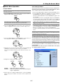
z Basic Menu Operation .............................................................. 8-2
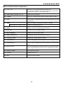
x List of Direct Button Combinations ........................................ 8-3
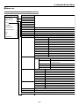
c Menu tree ................................................................................... 8-4
v Menu Descriptions & Functions .............................................. 8-7
Adjust (Source) ........................................................................... 8-8
Picture ................................................................................. 8-8
Video Adjust ........................................................................ 8-8
Picture Management ........................................................... 8-9
Image Options ................................................................... 8-10
Option Adjust ..................................................................... 8-10
Lens Memory ..................................................................... 8-11
Signal Type ........................................................................ 8-11
Sound ....................................................................................... 8-11
Ref. Adjust ................................................................................ 8-12
Using 3D Reform ............................................................... 8-12
Screen Type ....................................................................... 8-12
Reference White Balance .................................................. 8-12
Reference Color Correction ............................................... 8-12
Reference Lens Memory ................................................... 8-13
Factory Default ......................................................................... 8-13
Projector Options ...................................................................... 8-13
Menu ................................................................................. 8-13
Setup ................................................................................. 8-15
Lamp Settings ................................................................... 8-18
Link Mode .......................................................................... 8-18
LAN Mode ......................................................................... 8-19
Setting a Password ............................................................ 8-23
Security ............................................................................. 8-24
Tools ......................................................................................... 8-25
Timer ................................................................................. 8-25
Using Capture (GT5000 only) ........................................... 8-27
Using PC Card Files .......................................................... 8-27
Using ChalkBoard ............................................................. 8-27
Help .......................................................................................... 8-27
Contents ............................................................................ 8-27
Source Information ............................................................ 8-27
Projector Information ......................................................... 8-28
Test Pattern ............................................................................... 8-28
2. Installation
z Setting Up Your Projector ........................................................ 2-2
Screen Size and Projection Distance ......................................... 2-2
x Lens Shift Adjustable Range ................................................... 2-4
c Optional Lens Installation ....................................................... 2-6
v Making Connections ................................................................ 2-8
Connecting Your PC or Macintosh .............................................. 2-8
To connect Scart Output ............................................................. 2-9
Connecting an External Monitor ................................................. 2-9
Connecting Your DVD Player .................................................... 2-10
Connecting Your VCR or Laser Disc Player .............................. 2-11
Connecting to a Network .......................................................... 2-12
Connecting the Supplied Power Cable ..................................... 2-13
3. Projecting an Image (Basic Operation)
z Turning on the Projector .......................................................... 3-2
x Selecting a Source ................................................................... 3-3
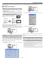
c Adjusting the Picture Size and Position ................................. 3-3
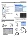
v Correcting the Horizontal and Vertical Keystone Distortion (3D
Reform) ..................................................................................... 3-4
b Optimizing RGB Picture Automatically .................................. 3-6
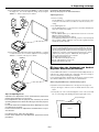
n Turning Up or Down Volume .................................................... 3-6
m Turning off the Projector .......................................................... 3-7
4. Convenient Features
z Turning Off the Image and Sound ...........................................
x Enlarging and Moving a Picture ..............................................
c Getting the On-line Help and Information ..............................
v Using a USB Mouse .................................................................
b Using a USB HUB Function .....................................................
n Changing Background Logo ...................................................
m Making Freehand Drawings on
, Projected Image (ChalkBoard) ................................................
. Lens Memory ............................................................................
4-2
4-2
4-2
4-3
4-3
4-4
4-4
4-5
9. Maintenancez Replacing the Lamp ......... 9-2
z Replacing or Cleaning the Filter ............................................. 9-3
x Cleaning the Cabinet and the Lens ......................................... 9-4
5. Using the Viewer
z Making the Most out of the Viewer Function ......................... 5-2
x Operating the Viewer Function from the Projector
(playback) ................................................................................. 5-3
10. Appendix
z USB Memory Device or USB Memory Card Reader Support ........ 10-2
x Troubleshooting ...................................................................... 10-3
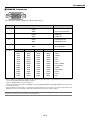
c Specifications ......................................................................... 10-5
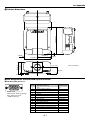
v Cabinet Dimensions ............................................................... 10-7
b Pin Assignments of D-Sub RGB Input Connector ............... 10-7
n Compatible Input Signal List ................................................. 10-8
m REMOTE 1 Connector ............................................................ 10-9
, PC Control Codes and Cable Connection .......................... 10-10
Cable Connection ................................................................... 10-10
PC Control Connector (D-SUB 9P) ......................................... 10-10
. Using Software Keyboard .................................................... 10-10
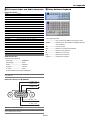
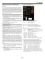
⁄0 Operation Using an HTTP Browser ..................................... 10-11
6. Using the Projector in a Network
z End User License Agreement .................................................
x Introduction ...............................................................................
c Supported Projectors ...............................................................
v Equipment Connections and Settings ....................................
b Software Installation ................................................................
n Starting/Exiting the Software ..................................................
m Troubleshooting ........................................................................
6-2
6-3
6-4
6-5
6-6
6-7
6-8
iv
1
Introduction
○ ○ ○ ○ ○ ○ ○ ○ ○ ○ ○ ○ ○ ○ ○ ○ ○ ○ ○ ○ ○ ○ ○ ○ ○ ○ ○ ○ ○ ○ ○ ○ ○ ○ ○ ○ ○ ○ ○ ○
z What's in the Box? .................................................... 1-2
x Introduction to the Projector ..................................... 1-3
c Getting to Know Your Projector ................................. 1-4
Attaching the lens hood cap to the lens hood with the supplied string and rivet . 1-6
Carrying the Projector ......................................................................................... 1-6
Top Features ........................................................................................................ 1-7
Terminal Panel Features ...................................................................................... 1-8
v Remote Control Features ....................................... 1-10
Remote Control Precautions ............................................................................. 1-12
Remote Control Battery Installation ................................................................... 1-12
Operating Range for Wireless Remote Control ................................................. 1-12
Using the Remote Control in Wired Operation .................................................. 1-13
1. Introduction
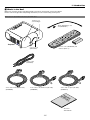
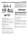
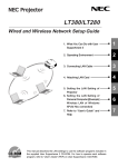
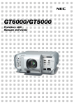
z What's in the Box?
Make sure your box contains everything listed. If any pieces are missing, contact your dealer.
Please save the original box and packing materials if you ever need to ship your Projector.
NOTE: Lenses are optional. Order lenses from your Dukane dealer.
Terminal cover
(Left and Right)
FO
C
U
S
CAR
ZO
O
M
PC
D
1
F
PC
CAR
String (024C04541) and
rivet (024C04531)
Z
D
2
LE
FT
LA
D
O
W
N
M
P
LE
NS
1
SH
IFT
LA
M
P
U
P
ST
R
IG
H
T
2
ENT E R
AT
US
M
O
N
/S
TA
N
D
EN
ER
S
E
LE
C
T
W
CEL
PO
CA
N
U
3D
BY
REF
O
3D
RM
AU
TO
AD
ST
A
JU
Projector
Remote control (079646633) and
batteries (AAA⳯2)
Lens hood cap
(024F37661)
Remote cable
(073499391)
Power cable for Europe (AC 230V)
(07N080003)
Power cable for North America (AC 120V)
(07N080208)
Power cable for Japan (AC 100V)
(07N080113)
nt
rta ion
po at
Im orm
f
In
Document
User's Manual
1-2
1. Introduction
x Introduction to the Projector
This chapter introduces you to the 9060 high end
fixed installation projector and describes key features and controls.
Congratulations on Your Purchase of the
projector
• Double stackable for built in redundancy and high light output
requirements
• Built in 5W⳯2 speakers for an integrated audio solution
• Two timer settings - On/Off with programming or Sleep timer
that counts down at selected intervals
• 12V low voltage Screen Trigger output
The 9060 is a sophisticated three panel, dual
lamp XGA LCD projector. With the 9060 you will be
able to project images up to 500" (measured diagonally) from
your DVD player, VCR, satellite hookup, HDTV source, PC, Workstation or Macintosh computer (desktop or notebook) and images from you digital camera PC Card or compact flash memory.
The Dukane 9060 incorporates integrated networking access
through the RJ45 input or provides for wireless network connectivity from an optional wireless network PC card. With extensive
input and output panels, optional long life lamp, full suite of quickchange lenses and a full function remote, the 9060
will let you immerse yourself in large screen viewing.
Features you’ll enjoy on the 9060:
• Integrated RJ45 connector for wired networking ability
• Two optional modular card slots allow for future projector growth
with the ability to add additional input cards
• Dual PC card slots provide for optional wireless/wired network
connectivity or PC Card usage
• Email projector error status information to selected individuals
• Power Horizontal and Vertical lens shift for optical display corrections
• Lens memory controls lens attributes (zoom, focus, shift) depending on input resolution and input selected for fast and easy
source transitions
• Designed and developed SweetVisionTM technology for
enhanced video image display, more vibrant colors and blacks
richer with detail
• 3D Reform enhanced image technology for increased projector versatility that provides for horizontal, vertical and diagonal
keystone correction (allows for positioning the projector in off
center locations in the room and still get aligned images)
• Display 16:9 or 4:3 information and fill the screen
• Easy set up and operation
• Eco-mode™ lamp technology for increased lamp life and energy savings
• VORTEX Technology Plus™ for uncompromising display of
video and data. Improves white level, color accuracy, dynamic
range, and display of varying levels of black in an image
• Wireless remote control operation
• External control via RS232, USB or Network
• Advanced AccuBlend intelligent pixel blending
technology provides for extremely accurate image compression and HDTV (1920⳯1080) display resolution*2.
• Supports most IBM VGA, SVGA, XGA, Macintosh, component
signal (YCbCr/YPbPr) or other RGB signals within a horizontal frequency range of 15 to 100 kHz and a vertical frequency
range of 48 to 120 Hz. This includes NTSC, NTSC4.43, PAL,
PAL-M, PAL-N, PAL60 and SECAM standard video signals
NOTE: Composite video standards are as follows:
NTSC: U.S. TV standard for video in U.S. and Canada.
NTSC4.43: TV standard used in Middle East countries.
PAL: TV standard used in Western Europe.
PAL-M: TV standard used in Brazil.
PAL-N: TV standard used in Argentine, Paraguay and Uruguay.
PAL60: TV standard used for NTSC playback on PAL TVs.
SECAM: TV standard used in France and Eastern Europe.
*1 The 9060 meets ADA508 compliance, the latest American
government regulation which provides for closed captioning,
including a menu system that can be viewed by colorblind users. This model also meets Executive Order 13221 requirement for standby operation, which consumes less than 1 watt.
*2 HDTV 1080P (1920⳯1080), HDTV 1080i (1920⳯1080), HDTV
720 p (1280⳯720) and 1600⳯1200 are displayed with
Advanced AccuBlend technology on the 9060.
• HDTV (1080p, 1080i, 720p) and SDTV (576p, 576i, 480p, 480i)
compatibility
• 9060 supports a native resolution of XGA (1024⳯768) and
• Intelligent lamp technology offers up to six user lamp settings
to maximize light output or lamp life and provide for built in
redundancy
• Smart security settings for password protection, control panel
lock, menu lock and PC card protection key to help prevent
unauthorized access and adjustments to the projector
• ADA508 and Executive Order 13221 Federal Government compliance *1
• NEC 3D 10-bit video decoder for expanded black levels and
adaptive gamma correction
• High performance optional long life lamp for low total operating costs
• Digital photo viewer to display larger than life images from your
digital cameras PC card or compact flash card
1-3
1. Introduction
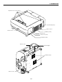
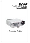
c Getting to Know Your Projector
Controls
N
D
ER
W
PO
TA
O
N
/S
TO
AU
S
U
AT
ST
3D
CE L
2
P
M
LA
1
ENTER
P
M
LA
D
AR
C
U
N
2
S
E
LE
C
T
CAN
3D
M
R
O
EF
R
A
ST
JU
AD
BY
Terminal panel (Left)
M
Z
FO
C
U
S
ZO
O
LE
U
FT
P
LE
NS
SH
PC
IFT
D
O
D
AR
C
R
W
1
N
H
IG
T
PC
ME
F
Lens hood
Lamp cover 1 (Right)
AU
DIO
OU
T
L/M
ON
O
RG
B1
AU
DIO
Terminal panel (Right)
R
L/M
RG
B2
ON
AU
DIO
DV
O
SL
OT
I
1
R
R/C
r
SL
OT
2
RG
B OU
T
G/Y
VIDE
O
S-VI
L/M
DE
O
B/C
b
H/
HV
ON
O
L/M
ON
O
V
R
R
Lens (optional)
US
B (MO
USE/H
UB)
Built-in Security Slot (
US
B (PC
2
)
PC
PC
CA
RD
CO
NT
RO
L
1
IN
Remote sensor
LA
N
OU
T
SC
RE
MO
TE
TR
IGGE
R
RE
MO
TE
1
2
Carrying handle
IN
OU
T
AC
IN
Air filter (Right)
Lens hood cap
Speaker 5W (Stereo)
AC INPUT
Connect the supplied
power cable’s three-pin
plug here.
Foot (four)
Rotate to fine-adjust the height of
each foot (max. 0.6”/15mm).
*NOTE: Slot for Kensington MicroSaver Security System
This security slot supports the MicroSaver® Security System.
MicroSaver® is a registered trademark of Kensington Microware Inc. The logo is trademarked and owned by Kensington Microware Inc.
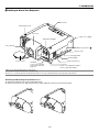
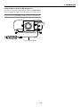
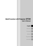
Attaching and Removing the Terminal Covers
S
E
C
R
U
SO
A
AU
TO
AD
D
N
TA
/S
N
JU
BY
ST
To remove the terminal cover, push and hold the latch.
To attach the terminal cover, align the protrusions inside and push it until you feel it click into place.
AUD
IO
OUT
L/MO
NO
RG
B1
AUD
IO
R
DV
L/MO
NO
RG
B2
SLO
T1
AUD
IO
I
R
R/Cr
OPT
ION
2
RGB
OUT
G/Y
VID
EO
S-V
B/Cb
IDE
O
H/
HV
L/MO
NO
R
L/MO
NO
V
R
USB
A
USB
B
PC
PC
2
CAR
D
CON
TRO
L
IN
LAN
OUT
1
SC
TRI
REM
OTE
GGE
R
REM
OTE
1
2
IN
OUT
AC
1-4
IN
)*
1. Introduction
Depression for foot (4 locations)
F
Z
FO
C
U
S
O
LE
ZO
U
FT
M
P
LE
NS
SH
IFT
PC
D
RD
CA
IG
H
N
1
W
R
O
T
PC
2
U
N
RD
CA
ME
S
P
M
LA
E
LE
C
1
EN T E R
T
M
LA
P
2
CAN
3D
3D RM
FO
RE
CE L
US
AT
ST
AU
A
TO
AD
ST
BY
JU
ER
W
PO
D
N
TA
/S
N
O
Speaker 5W (Stereo)
Remote sensor
Remote sensor
Ventilation (outlet)
Air filter (Left)
Lamp cover 2 (Left)
Ventilation (outlet)
Remote sensor
REMOTE 1
OUT
SC TRIGGER
IN
AC IN
IN
REMOTE 2
PC CARD
PC CONTROL
USB (MOUSE/HUB ) USB (PC )
Ventilation (inlet)
R/Cr
G/Y
V
L/MONO
R
L/MONO
R
Remote sensor
H/
HV
B/Cb
RGB 2
VIDEO
RGB OUT
L/MONO
R
S-VIDEO
L/MONO
AUDIO
AUDIO OUT
R
RGB 1
AUDIO
SLOT 1
SLOT 2
DVI
OUT
LAN
2
1
Air filter (Right)
1-5
1. Introduction
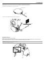
Attaching the lens hood cap to the lens hood with the supplied string and rivet
1. Thread the string through the hole on the lens hood cap.
Lens hood cap
String
Rivet
AUDIO
R/Cr
AUDIO
G/Y
B/Cb
H/HV
R
L/MONO
R
L/MONO
V
S-VIDEO
VIDEO
RGB OUT
R
RGB 2
L/MONO
AUDIO OUT
R
RGB 1
L/MONO
OPTION 1
DVI
OPTION 2
2. Use the rivet to attach the string to the bottom of the projector.
Carrying the Projector
Always carry your projector by the handle.
Ensure that the power cable and any other cables connecting to video sources are disconnected before moving the projector.
When moving the projector or when it is not in use, cover the lens with the lens hood cap.
CAUTION: Do not put the projector on its side when the lamp is on.
Doing so may cause damage to the projector.
FOCUS
Z
PC CARD 1
ZOOM
F
UP
LAMP 1
LENS SHIFT
DOWN
LEFT
PC CARD 2
LAMP 2
RIGHT
ENT
ER
MENU
POWER
L
CE
CAN
SELECT
STATUS
3D
A
3D REFORM AUTO ADJUST
ON/STAND BY
1-6
1. Introduction
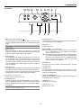
Top Features
14 13 12
10 9
8 11 6
7
MENU
UP
Z
3D
LEFT
NT
5
PC CARD 2
LAMP 1
ER
LAMP 2
4
A
3D REFORM AUTO ADJUST
SELECT
DOWN
ZOOM
PC CARD 1
1. POWER Button (ON / STAND BY)(
RIGHT
E
FOCUS
LENS SHIFT
L
F
CAN
CE
STATUS
3
ON/STAND BY
POWER
2
1
7. AUTO ADJUST Button
)
Use this button to adjust Position-H/V and Pixel Clock/Phase
for an optimal picture. See page 3-6.
Use this button to turn the power on and off when the main
power is supplied and the projector is in standby mode or idle
mode.
NOTE: To turn on or off the projector, press and hold this button for a minimum
of two seconds.
8. MENU Button
Displays the menu.
9. SELECT 왖왔왗왘 (+) (–) / Volume Buttons
2. POWER Indicator
왖왔 : Use these buttons to select the menu of the item you
wish to adjust. When no menus appear, these buttons
work as a volume control.
왗왘 : Use these buttons to change the level of a selected menu
item. A press of the 왘 button executes the selection. When
the menus or the Viewer tool bar is not displayed, these
buttons can be used to select a slide, or to move the
cursor in Folder List or Slide List.
When this indicator is green, the projector is on; when this
indicator is orange, it is in standby or idle mode. See the Power
Indicator section on page 10-3 for more details.
3. STATUS Indicator
If this light blinks red rapidly, it indicates that an error has occurred, the lamp cover is not attached properly or the projector
has overheated. If this light remains orange, it indicates that
you have pressed a cabinet key while the Control Panel Key
Lock is enabled. See the Status Indicator section on page 103 for more details.
10. ENTER Button
Executes your menu selection and activates items selected
from the menu.
4. LAMP Indicator 1/2
If this light blinks red rapidly, it's warning you that the lamp has
reached the end of its usable life. After this light appears, replace the lamp as soon as possible (See page 9-2). See the
Lamp Indicator section on page 10-3 for more details.
11. CANCEL Button
Press this button to exit "Menus". Press this button to return
the adjustments to the last condition while you are in the adjustment or setting menu.
12. LENS SHIFT 왖왔왗왘 Button
5. PC CARD Access Indicator 1/2
Adjust the lens offset by shifting the projected image position
horizontally and / or vertically.
Lights while accessing a PC card.
6. 3D REFORM Button
Press this button to enter 3D Reform mode to correct the keystone (trapezoidal) distortion, and make the image square.
Press to toggle between Cornerstone and Keystone adjustment mode.
13. ZOOM Button (+/-)
Zoom the lens in and out.
14. FOCUS Button (+/-)
NOTE: Pressing and holding this button for a minimum of 2 seconds will reset
3D Reform correction setting values to zero.
1-7
Adjust the lens focus.
1. Introduction
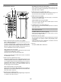
DVI AUDIO Input Mini Jack (Stereo Mini)
This is where you connect the audio output from your computer when connected to the DVI input. A commercially available audio cable is required.
Terminal Panel Features
2 1
AUDIO
3
4. RGB OUT Connector (Mini D-Sub 15 Pin)
You can use this connector to loop your computer image to an
external monitor from the RGB 1 or 2 input source.
8
5. VIDEO IN Connector (BNC)
Connect a VCR, DVD player, laser disc player, or document
camera here to project video.
RGB 1
AUDIO OUT
SLOT 1
7
DVI
L/MONO
SLOT 2
L/MONO
R
R
AUDIO
RGB 2
R/Cr
VIDEO AUDIO Input Jacks R/L (RCA)
These are your left and right channel audio inputs for stereo
sound from a Video source.
G/Y
RGB OUT
4
6. S-VIDEO IN Connector (Mini DIN 4 Pin)
Here is where you connect the S-Video input from an external
source like a VCR.
B/Cb
VIDEO
S-VIDEO
H/
HV
NOTE: S-Video provides more vivid color and higher resolution than the traditional composite video format.
V
L/MONO
L/MONO
R
R
S-VIDEO AUDIO Input Jacks R/L (RCA)
These are your left and right channel audio inputs for stereo
sound from an S-Video source.
5 6
1. RGB 1 Connectors [R/Cr, G/Y, B/Cb, H/V, V] (BNC)
Connect R,G,B,H (Horizontal sync) and V (Vertical sync) outputs of external equipment.
If using a component with a combined sync (SYNC) output,
connect it to the H/V terminal. When using luminance and colordifference signals of HDTV and DVD, connect Pr/Cr to the R, Y
to the G and Pb/Cb to the B input of the projector.
7. AUDIO OUT Jacks R/L (RCA)
You can use this connector to output sound from the currently
selected input source (RGB 1, RGB 2, DVI (DIGITAL), Video
or S-Video).
Output sound level can be adjusted in accordance with the
sound level of the internal speaker.
8. Slot 1/2
For optional RGB, SDI or DVI board.
RGB 1 Audio Input Jacks (RCA)
L/MONO: This is your left channel audio input for stereo sound
coming from the RGB Input 1 source.
This also serves as your monaural audio input.
R: This is your right channel audio input for stereo sound from
the RGB Input 1 source.
2. RGB 2 Connector (Mini D-sub 15 Pin)
Connect your computer or other analog RGB equipment such
as IBM compatible or Macintosh computers. This also serves
as a component input connector that allows you to connect a
component video output of component equipment such as a
DVD player. This connector also supports SCART output signal. See page 2-9 for more details.
RGB 2 Audio Iput Mini Jack (Stereo Mini)
This is where you connect audio output from your computer or
DVD player connected to the RGB2 input. A commercially available audio cable is required.
3. DVI IN Connector (DVI-D 24 Pin)
This connector can be used to accept digital signal output from
a computer with a DVI connector.
1-8
1. Introduction
6. SC. TRIGGER Mini Jack
When the projector is powered ON the screen trigger output
sends a low voltage trigger to the screen controller and the
screen will go down. When the projector is powered OFF the
screen trigger stops sending a low voltage trigger to the screen
controller and the screen will go up.
Terminal Panel Features
1
2
3
4
2
USB (MOUSE/HUB) USB (PC)
1
PC CARD
Stereo mini cable
(not supplied)
7
IN
REMOTE 1
OUT
6
Tip (12V)
Ring (0V)
LAN
PC CONTROL
5
NOTE: To use this feature, you must turn on the Screen Trigger function. See
page 8-17.
SC TRIGGER
REMOTE 2
IN
8
9
Sleave (ground. 0V)
NOTE: Screen controllers are supplied and supported by screen manufacturers.
OUT
NOTE: Do not use this jack for anything other than intended use. Connecting
wired remote control to the SC. TRIGGER Mini Jack causes damage to the remote control.
AC IN
10
7. LAN Port (RJ-45)
This port is typically used for UTP Ethernet/Fast Ethernet. Use
this connector to control the projector on a LAN. See page
2-12.
11
1. USB Port [MOUSE/HUB] (Type A)
Connect a USB mouse. You can operate the menu or Viewer
with a USB mouse via this port.
• A USB-supported scanner or PC peripheral can be connected
to this port. (USB Hub Function. See page 4-3)
8. REMOTE 1 (Mini D-Sub 15 Pin)
This terminal allows external control of the projector by use of
contact closure. See page 10-9.
9. REMOTE 2 Mini Jacks (IN/OUT)
IN: wired remote control input.
OUT: for daisy-chaining multiple projectors and operating them
with the same remote control. To do so, connect to a second
projector’ s IN terminal to relay the input at the IN terminal of
the first projector until all the projectors are connected.
2. USB Port [PC] (Type B)
Connect this port to the USB port (type A) of your PC using a
USB cable. This port also serves as a PC Control port by using
Dynamic Image Utility 2.0 included on the supplied CD-ROM.
3. PC CARD Slot 1/2
Insert a PC card, commercially available flash memory card or
optional wireless LAN card here.
There are two slots: Slot 1 and Slot 2.
4. PC CARD Eject Button 1/2
Press to eject a PC card partially. Each slot has its own eject
button: 1 and 2.
5. PC CONTROL Connectors (Mini D-Sub 9 pin)
For system expansion such as PC-Control using Dynamic Image Utility included on the supplied User Supportware CDROM or RS232C control from an external control system.
10. Main Power Switch
When you plug the supplied power cable into an active wall
outlet and turn on the Main Power switch, the POWER indicator turns orange and the projector is in standby mode. See
page 3-2.
11. AC IN
Connect the supplied power cable’s three-pin plug here.
Three types of power cable are supplied with this projector:
three-pin type for U. S. A. and Canada. Two-pin type for Europe
and Japan.
IN: connect to the external equipment such as a PC or control
system.
OUT: for daisy-chaining multiple projectors and operating them
with the same external equipment. To do so, connect to a second projector’ s IN terminal to relay the input at the IN terminal
of the first projector until all the projectors are connected.
1-9
1. Introduction
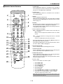
v Remote Control Features
1. POWER ON
Press and hold this button for a minimum of two seconds to
turn on the projector when the main power is supplied and the
projector is in standby mode or idle mode.
2. POWER OFF
Press and hold this button for a minimum of two seconds to
turn off the projector.
POWER
OFF
ON
1
2
MENU
5
-
BS
ADDRESS
+
3
ENTER
4
6
7
ADJUST
IMAGE
PICTURE WHITE BAL. PROJECTOR
9
10
ABC
DEF
GHI
1
2
3
JKL
MNO
PQR
4
5
6
STU
VWX
YZ/
7
8
9
,.
UNDO
CANCEL
INFO.
HELP
POSITION PIXEL
AUTO
TEST
LENS
MUTE
SHUTTER
20
21
22
PICTURE SOUND
OSD
KEYSTONE AMPLITUDE ENTRYLIST
R
G
B
11
14
15
16
18
19
23
MAGNIFY
+
+
-
-
25
24
FOCUS
26
ZOOM
LENS
4. ENTER
Executes the menu selection and activates items selected from
the menu. When the slider or dialog box is displayed:
Pressing this button confirms adjustments/setting and returns
to the previous menu display.
5. Select (Up/Down/Left/Right)
왖왔: Use these buttons to select the menu of the item you
wish to adjust.
When no menus appear, these buttons work as a volume
control.
0
12
13
17
8
3. MENU
Press to display the main menu.
While pressing and holding CTL, press this button to display
the Remote Control ID dialog box to specify the remote control
ID. See page 7-2.
왗왘: Use these buttons to change the level of a selected
menu item.
A press of the 왘 button executes the selection.
Pressing and holding CTL, then pressing 왗 button works as a
Back Space key in the entry screen.
Pressing and holding CTL, then pressing this button moves
the menu, slider, toolbar or dialog box.
6. ADJUST WHITE BAL.
Press to display the Picture Management screen.
7. ADJUST PICTURE
Press to display the Picture adjustment screen. Pressing this
button sequentially selects adjustment screens.
8. IMAGE/PROJECTOR
Press to display the Image Option screen. Pressing this button
sequentially selects Image Options screens.
While pressing and holding CTL, pressing this button rotates
Projector Options screens.
9. Source / Input
Press to select input or to name a signal.
CTL
1
2
3
4
5
6
7
8
9
0
Selects RGB 1 input.
Selects RGB 2 input.
Selects DVI (DIGITAL) input.
Selects VIDEO input.
Selects S-VIDEO input.
Selects Viewer input
Selects LAN input
Selects OPTION SLOT 1* (available for optional SDI board)
Selects OPTION SLOT 2* (available for optional SDI board)
Sequentially selects: RGB1 (VIDEO) → RGB1 (S-VIDEO) .
*
This button toggles between input 1 and 2.
NOTE: While pressing and holding CTL, pressing this button switches to the
selected signal found in the Entry List.
1-10
1. Introduction
25. MAGNIFY/ZOOM (+/–)
Magnify the size of a target portion.
While pressing and holding CTL, pressing this button allows
you to zoom the lens in and out.
2
E
D
H
R
JU
D
A
N
E
F
F
O
R
E
W
O
P
B
S
O
-
N
+
M
IC BC
E
W
S
E
U
15. PIXEL
Displays the Position/Clock screen to adjust the clock and
phase.
T
N
S
ES
DR ER
AD T
IM
A
L.
G
E
14. HELP
Provides online help.
M
26. CTL
Used in conjunction with other buttons, similar to a shift key on
a computer.
TU
13. TEST
Press to display the test pattern. Pressing this button sequentially selects test patterns.
24. FOCUS (+/–)
While pressing and holding CTL, pressing this button allows
you to adjust the lens focus.
B
E
IT F
12. INFO
Displays the "Source Information" or "Projector Information"
window. This button toggles between these two windows.
While pressing and holding CTL, pressing this button stores
lens position settings.
23. ENTRY LIST (B)
Press to display the Entry List screen.
Pressing and holding CTL and then ENTRY LIST buttons simultaneously, enters a signal in the Entry List when you are
not displaying a test pattern.
When the test pattern is displayed, while pressing and holding
CTL, pressing this button displays a blue test pattern.
O
PR
11. CANCEL
Press to exit the menu.
Press this button with CTL to return to the previous menu without closing adjustment/setting screen while the menus appear.
This feature allows you to adjust or set several items concurrently.
22. AMPLITUDE (G)
Service personnel only.
When the test pattern is displayed, while pressing and holding
CTL, pressing this button displays a green test pattern.
A
10. UNDO
Press to return the adjustments and settings to the previous
condition. While pressing and holding CTL, pressing this button clears the entire menus or adjustment/setting screen. At
this time the adjustments/settings are stored in memory except the items on the setting screen with "OK" and "Cancel"
buttons such as the Menu and the Setup screen.
16. AUTO (RGB only)
Press to adjust Position-H/V and Pixel Clock for an optimal
picture.
27
28
17. POSITION
Press to display the Position screen; press again to display the
Blanking screen.
While pressing and holding CTL, pressing this button displays
the Lens Shift adjustment screen.
27. Remote Jack
Connect your remote cable here for wired operation.
18. MUTE SOUND
Turns off the sound for a short period of time. Press again to
restore the sound.
28. Infrared Transmitter
Direct the remote control toward the remote sensor on the projector cabinet.
19. MUTE OSD
Press to turn off the on-screen display. Press again to restore
the on-screen display.
NOTE: You can also turn off the on-screen display forcibly by pressing and
holding CTL and then pressing MUTE OSD (Forced On-Screen Mute Mode) ;
doing this again restores it. In this case any adjustment will still change the
projector's memory settings. This mode is available even when input is switched
to another or the power is turned off the main power.
20. MUTE PICTURE
Press to turn off the picture for a short period of time. Press
again to restore the picture.
21. KEYSTONE (R)
Press to display the Keystone Correction (3D Reform) screen.
This button toggles between “Cornerstone” and “Keystone”.
When the test pattern is displayed, while pressing and holding
CTL, pressing this button displays a red test pattern.
NOTE: Pressing and holding this button for a minimum of two seconds will
reset 3D Reform correction setting values to zero.
1-11
1. Introduction
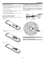
Remote Control Precautions
Operating Range for Wireless Remote Control
• The remote control system may not function when direct sunlight or
strong illumination strikes the remote control sensor of the main unit, or
when there is an obstacle in the path.
The infrared signal operates by line-of-sight up to a distance of
approximately 7m (20 feet) and a 60 degree angle of the remote
sensor.
The projector will not function if there are objects between the
remote sensor and the remote control or if strong light falls on
the remote sensor. Weak batteries will also prevent the projector
from operating properly.
• When remote control buttons are pressed and held, projector’s function
keys may not operate.
• Do not subject to strong shock.
• Do not allow water or other liquid to splash on the remote control. If the
remote control gets wet, wipe it dry immediately.
• Avoid exposure to heat and steam.
• Remove the batteries from the remote control when the remote control
is not going to be used for a long period.
Side View
30˚
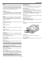
Remote Control Battery Installation
7m
Installing the Remote Control Batteries
When it comes time to replace the batteries, two "AAA" type will
be required.
30˚
Remote sensors on the
projector cabinet
1. Press and open the cover.
7m
2. Align and insert the batteries according to the (+) and (-) indications
inside the case.
Remote control
NOTE: You cannot operate the projector using the remote control if:
• The remote control ID is not set to [None].
• The remote ID is not the same as the projector ID.
See page 7-2 for setting remote ID and projector ID.
3. Replace the cover.
1-12
1. Introduction
Using the Remote Control in Wired Operation
Connect one end of the supplied remote cable to the REMOTE 2 IN
mini jack and the other end to the remote jack on the remote control.
NOTE: Do not use this jack for anything other than intended use. Connecting the wired
remote control to the SC. TRIGGER Mini Jack causes damage to the remote control.
AUDIO
2
DVI
RGB 1
AUDIO OUT
SLOT 1
L/MONO
SLOT 2
USB (MOUSE/HUB) USB (PC)
1
PC CARD
REMOTE 2
IN
L/MONO
R
R
AUDIO
RGB 2
LAN
PC CONTROL
R/Cr
IN
REMOTE 1
G/Y
RGB OUT
OUT
B/Cb
VIDEO
SC TRIGGER
S-VIDEO
H/
HV
REMOTE 2
IN
OUT
V
L/MONO
AC IN
L/MONO
R
R
Terminal panel (Right)
BS
+
POWER
2
DEF
ADJUST
OFF
1
ABC
MENU
ADDRESS
ENTER
ON
6
9
3
YZ /
GHI
PQR
IMAGE
PICTURE WHITE BAL. PROJECTOR
HELP
CANCEL
8
5
VWX
INFO.
UNDO
MNO
,.
7
0
4
JKL
STU
TEST
B
+
-
AUTO
ZOOM
MAGNIFY
G
MUTE
POSITION PIXEL
LENS
SHUTTER
LENS
+
-
PICTURE SOUND
OSD
KEYSTONE AMPLITUDE ENTRYLIST
R
CTL
FOCUS
Remote cable (supplied)
1-13
2
Installation
○ ○ ○ ○ ○ ○ ○ ○ ○ ○ ○ ○ ○ ○ ○ ○ ○ ○ ○ ○ ○ ○ ○ ○ ○ ○ ○ ○ ○ ○ ○ ○ ○ ○ ○ ○ ○ ○ ○ ○
z Setting Up Your Projector .......................................... 2-2
Screen Size and Projection Distance .................................................................. 2-2
x Lens Shift Adjustable Range .................................... 2-4
c Optional Lens Installation ......................................... 2-6
v Making Connections ................................................. 2-8
Connecting Your PC or Macintosh ....................................................................... 2-8
To connect Scart Output ................................................................................. 2-9
Connecting an External Monitor .......................................................................... 2-9
Connecting Your DVD Player ............................................................................. 2-10
Connecting Your VCR or Laser Disc Player ....................................................... 2-11
Connecting to a Network ................................................................................... 2-12
Connecting the Supplied Power Cable .............................................................. 2-13
2-1
2. Installation
This chapter describes how to set up your projector and how to connect video and audio sources.
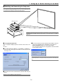
z Setting Up Your Projector
Your Projector is simple to set up and use. But before you get started, you must first:
1. Determine the image size
4. Connect the supplied power cable.
2. Set up a screen or select a non-glossy white wall onto which you can
project your image.
5. Set up the projector.
3. Install the optional lens to the projector.
7. Make settings or adjustments on the projector.
6. Connect a PC, VCR, DVD player, or other equipment.
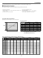
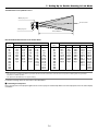
Screen Size and Projection Distance
Applicable lens and throw distance/ List of screen sizes
List of Screen Sizes
Screen size
Height
Screen size (Diagonal)
Width
40"
60"
80"
100"
120"
150"
200"
250"
300"
400"
500"
Formulas:
Width (H)
Height (V)
m
inch
m
inch
0.8
31.5
0.6
23.6
1.2
47.2
0.9
35.4
1.6
63.0
1.2
47.2
2.0
78.7
1.5
59.1
2.4
94.5
1.8
70.9
3.0
118.1
2.3
90.6
4.1
161.4
3.0
118.1
5.1
200.8
3.8
149.6
6.1
240.2
4.6
181.1
8.1
318.9
6.1
240.2
10.2
401.6
7.6
299.2
Screen width H (m)= Screen size⳯4/5⳯0.0254
Screen height V (m)= Screen size⳯3/5⳯0.0254
Screen width H (inch)= Screen size⳯4/5
Screen height V (inch)= Screen size⳯3/5
Table of Throw Distances and Screen Sizes for Optional Lenses
40"
60"
67"
72"
80"
84"
90"
100"
120"
150"
180"
200"
210"
240"
250"
270"
300"
400"
500"
GT10RLB
1.0
(m) (inches)
0.76 30.0
1.17 46.1
1.31 51.7
1.41 55.7
1.58 62.1
1.66 65.3
1.78 70.2
1.99 78.2
2.39 94.2
3.01 118.3
3.62 142.4
4.02 158.5
4.23 166.5
4.84 190.6
5.04 198.6
–– ––
–– ––
–– ––
–– ––
GT13ZLB
1.2-1.5
(m)
(inches)
0.91 - 1.15 36.0 - 45.2
1.40 - 1.75 55.2 - 69.0
1.57 - 1.97 62.0 - 77.4
1.70 - 2.12 66.8 - 83.3
1.89 - 2.36 74.5 - 92.9
1.99 - 2.48 78.3 - 97.6
2.14 - 2.66 84.1 - 104.8
2.38 - 2.96 93.7 - 116.7
2.87 - 3.57 112.9 - 140.5
3.60 - 4.48 141.8 - 176.2
4.33 - 5.38 170.6 - 212.0
4.82 - 5.99 189.9 - 235.8
5.07 - 6.29 199.5 - 247.7
5.80 - 7.20 228.4 - 283.4
6.04 - 7.50 238.0 - 295.4
6.53 - 8.11 257.2 - 319.2
7.27 - 9.01 286.1 - 354.9
––
––
––
––
GT19ZL
1.7-2.2
(m)
(inches)
1.30 - 1.74 51.0 - 68.4
1.99 - 2.65 78.3 - 104.2
2.23 - 2.97 87.8 - 116.7
2.40 - 3.19 94.6 - 125.7
2.68 - 3.56 105.5 - 140.0
2.82 - 3.74 110.9 - 147.2
3.02 - 4.01 119.1 - 158.0
3.37 - 4.47 132.7 - 175.9
4.06 - 5.38 159.9 - 211.7
5.10 - 6.74 200.7 - 265.4
6.14 - 8.11 241.6 - 319.2
6.83 - 9.02 268.8 - 355.0
7.17 - 9.47 282.4 - 372.9
8.21 -10.84 323.2 - 426.7
8.56 -11.29 336.8 - 444.6
9.25 -12.20 364.0 - 480.4
10.28 -13.57 404.9 - 534.1
––
––
––
––
GT20ZL
2.0-2.6
(m)
(inches)
1.53 - 2.03 60.1 - 80.0
2.34 - 3.10 92.1 - 122.0
2.62 - 3.47 103.3 - 136.7
2.83 - 3.74 111.3 - 147.2
3.15 - 4.16 124.1 - 164.0
3.32 - 4.38 130.6 - 172.4
3.56 - 4.70 140.2 - 185.0
3.97 - 5.23 156.2 - 205.9
4.78 - 6.30 188.2 - 247.9
6.00 - 7.90 236.3 - 310.9
7.22 - 9.50 284.3 - 373.9
8.04 -10.56 316.3 - 415.8
8.44 -11.10 332.4 - 436.8
9.66 -12.69 380.4 - 499.8
10.07 -13.23 396.4 - 520.8
10.88 -14.29 428.5 - 562.8
12.10 -15.89 476.5 - 625.7
––
––
––
––
2-2
GT24ZLB
GT34ZLB
2.2-3.2
3.2-4.8
(m)
(inches)
(m)
(inches)
––
––
––
––
2.58 - 3.86 101.6 - 152.0
––
––
2.90 - 4.32 114.0 - 170.3
––
––
3.12 - 4.66 122.9 - 183.3
––
––
3.48 - 5.19 137.1 - 204.3 5.10 - 7.81 200.6 - 307.6
3.66 - 5.45 144.2 - 214.7 5.36 - 8.21 211.0 - 323.3
3.93 - 5.85 154.8 - 230.4 5.76 - 8.81 226.6 - 346.9
4.38 - 6.52 172.6 - 256.5 6.41 - 9.81 252.5 - 386.2
5.28 - 7.84 208.0 - 308.8 7.73 -11.81 304.5 - 464.8
6.64 - 9.83 261.3 - 387.2 9.71 -14.80 382.3 - 582.7
7.99 -11.83 314.5 - 465.6 11.69 -17.80 460.2 - 700.6
8.89 -13.15 350.0 - 517.9 13.01 -19.79 512.1 - 779.2
9.34 -13.82 367.7 - 544.0 13.67 -20.79 538.1 - 818.5
10.69 -15.81 421.0 - 622.4 15.64 -23.79 615.9 - 936.5
11.14 -16.47 438.7 - 648.6 16.30 -24.78 641.9 - 975.8
12.04 -17.80 474.2 - 700.8 17.62 -26.78 693.8 -1,054.4
13.40 -19.79 527.4 - 779.2 19.60 -29.78 771.7 -1,172.3
17.90 -26.43 704.9 -1,040.6 26.19 -39.76 1,031.2 -1,565.3
––
––
32.79 -49.74 1,290.8 -1,958.4
2. Installation
GT24ZLB (H⳯2.2) -(H⳯3.2)
GT19ZL (H⳯1.7) -(H⳯2.2)
GT10RLB (H⳯1.0)
GT13ZLB (H⳯1.2) -(H⳯1.5)
GT20ZL (H⳯2.0) -(H⳯2.6)
Throw distance
GT34ZLB (H⳯3.2) -(H⳯4.8)
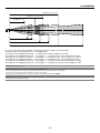
For screen sizes between 40" and 500" not indicated on the above table, use formulas below.
Projection Distance= Screen Width (H) ⳯ Lens Magnification
Throw distance for GT10RLB (m/inch)=H ⳯ 1.0 Distance from 0.8m to 5.0m/31.5" to 196.9"
Throw distance for GT13ZLB (m/inch)=H ⳯ 1.2 through H ⳯ 1.5 Distance from 1.0m to 9.0m/39.37" to 354.3"
Throw distance for GT19ZL (m/inch)=H ⳯ 1.7 through H ⳯ 2.2 Distance from 1.4m to 13.5m/55.12" to 531.5"
Throw distance for GT20ZL (m/inch)=H ⳯ 2.0 through H ⳯ 2.6 Distance from 1.7m to 15.8m/66.93" to 622"
Throw distance for GT24ZLB (m/inch)=H ⳯ 2.2 through H ⳯ 3.2 Distance from 2.6m to 26.4m/102.4" to 1039"
Throw distance for GT34ZLB (m/inch)=H ⳯ 3.2 through H ⳯ 4.8 Distance from 5.1m to 49.7m/200.8" to 1957"
NOTE: Distances may vary +/-5%.
NOTE: GT10RLB should be used only for “zero degree/no-offset” applications.
To set zero degree/no-offset, reset the lens position by using "Return to Factory Default" in "Ref. Lens Memory."
See page 8-13 for using "Return to Factory Default" to reset the lens position.
After resetting, perform fine adjustment on the lens position by using the LENS SHIFT button 왖왔왗왘.
NOTE: When using the projector with either the GT13ZLB or GT13ZL lens, it is recommended to select "Dual" in the Lamp Settings menu. This will provide the best
performance when operating the projector.
2-3
2. Installation
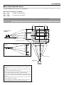
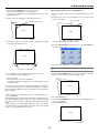
x Lens Shift Adjustable Range
The top right diagram shows the location of the image position in the lens. The lens can be shifted within the shaded area as shown
using the normal projection position as a starting point.
Maximum Possible Range for GT20ZL:
Up:
Down:
Right:
Left:
0.5 V
0.5 V
0.32 H
0.32 H
(V: height of projected image)
(H: width of projected image)
NOTE: Lens shift is not available on the GT10RLB rear lens. The GT10RLB should be used only for “zero degree/no-offset” applications.
NOTE: If lens is shifted in two directions combined, maximum range in either direction cannot be obtained due to rounded off area of lens. (example: shift up and right)
See top right diagram.
0.32H
Desktop/Front
Vertical
1H
0.32H
0.5V
0.5V
1V
1V
Normal position
0.5V
Normal projection position
0.32H
Ceiling/Front
Vertical
1H
0.32H
Normal position
1V
0.5V
Normal position
Horizontal
WARNING
* Installing the projector on the ceiling must be done by a qualified technician.
• Tilting the front of the projector up or down by more than 45° from
level could reduce lamp life by up to 20%.
• Only use your projector on a solid, level surface. If the projector falls,
you could be injured and the projector severely damaged.
• Do not use the projector where temperatures vary greatly. The projector must be used at temperatures between 32°F (0°C) and 95°F
(35°C).
• Do not expose the projector to moisture, dust, or smoke. This will
reduce the quality of the image.
• Ensure that you have adequate ventilation around your projector so
heat can dissipate. Do not cover the vents on the projector.
2-4
2. Installation
Lens Shift Adjustable Range (continued)
The top right diagram shows the location of the image position in the lens. The lens can be shifted within the shaded area as shown
using the normal projection position as a starting point.
Maximum Possible Range for GT13ZLB/GT19ZL/GT24ZLB/GT34ZLB:
Values in parentheses for GT13ZLB.
Up:
0.39V (0.32V) (V: height of projected image)
Down: 0.39V (0.32V)
Right: 0.24H (0.19H) (H: height of projected image)
Left:
0.24H (0.19H)
NOTE: Lens shift is not available on the GT10RLB rear lens. The GT10RLB should be used only for “zero degree/no-offset” applications.
NOTE: If lens is shifted in two directions combined, maximum range in either direction cannot be obtained due to rounded off area of lens. (example: shift up and right)
See top right diagram.
0.24H
(0.19H)
Desktop/Front
Vertical
1H
0.24H
(0.19H)
0.39V
(0.32V)
0.39V
(0.32V)
1V
1V
Normal position
0.39V
(0.32V)
Normal projection position
0.24H
(0.19H)
Ceiling/Front
Vertical
1H
0.24H
(0.19H)
Normal position
1V
0.39V
(0.32V)
Normal position
Horizontal
WARNING
* Installing the projector on the ceiling must be done by a qualified technician.
• Tilting the front of the projector up or down by more than 45° from
level could reduce lamp life by up to 20%.
• Only use your projector on a solid, level surface. If the projector falls,
you could be injured and the projector severely damaged.
• Do not use the projector where temperatures vary greatly. The projector must be used at temperatures between 32°F (0°C) and 95°F
(35°C).
• Do not expose the projector to moisture, dust, or smoke. This will
reduce the quality of the image.
• Ensure that you have adequate ventilation around your projector so
heat can dissipate. Do not cover the vents on the projector.
2-5
2. Installation
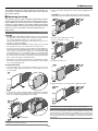
c Optional Lens Installation
This section describes how to install the lens.
Before installation
* Determine the optional lens to be used to obtain a desired projection distance. There are six optional lenses available:
GT13ZLB, GT19ZL, GT20ZL, GT24ZLB and GT34ZLB (Zoom lens)
GT10RLB (Short throw fixed-focus lens)
* Press the power button (ON/STAND BY) on the projector or POWER OFF button on the remote control for a minimum of two seconds to turn off the
power, wait 90 seconds (2 minutes in the optional extended life lamp) for the cooling fan to stop, turn off the main power switch then
disconnect the power cable.
Check that the projector has cooled off sufficiently before proceeding.
CAUTION
* The projector and lens contain high-precision parts. Do not induce shock to the projector or the lens.
* Do not touch the lens surface. Doing so can degrade the optical performance.
Preparation: Tools needed for installation:
A hexagonal driver and dust-protective sheets are supplied with the optional lens.
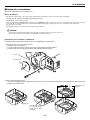
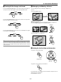
1. Remove the lens hood cap and lens hood.
q Remove the lens hood cap.
w Loosen and remove the 2 screws on the lens hood using the hexagonal driver.
e Remove the lens hood by pushing down and pulling the top toward you.
S-VI
L/M
O
B/C
b
3
O
L/M
Lens hood
DE
H/
HV
ON
ON
O
V
R
R
US
B (MO
USE/H
UB)
US
B (PC
2
)
PC
PC
Lens hood cap
CA
RD
CO
NT
RO
L
1
IN
LA
N
OU
T
SC
RE
MO
TE
TR
IGGE
R
RE
MO
TE
1
2
IN
1
OU
T
AC
IN
3
2
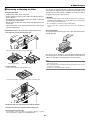
2. Attach a dust-protective sheet.
q Remove the shipping tape on the back of the lens hood. w Insert the dust-protective sheet included with your optional lens. Be
careful not to fold the sheet.
Hole
1
2
Shipping tape
Insert the dust-protective sheet with the aluminum side up while
bending it.
2-6
Align the holes on
the right.
2. Installation
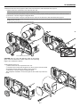
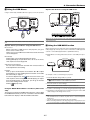
3. Mount the lens unit on the projector and connect the extension cable attached to the projector.
q Remove the lens cap from the rear end of the lens unit.
NOTE: Leave the front lens cap for protection while mounting the lens unit.
w Insert the lens unit so that the 4 screws on the lens unit are properly lined up with the 4 holes on the lens mount.
e Secure the 4 screws using the hexagonal driver.
r Insert the connector of the lens unit fully into the socket of the extension cable attached to the projector.
NOTE: The GT13ZL, GT19ZL, GT24ZL and GT34ZL optional lenses have one connector. The B type lenses (GT13ZLB, GT24ZLB and GT34ZLB) and
GT20ZL have two connectors.
To insert the connector into the 4-pin socket on the right side.
1
AU
DIO
AU
OU
T
AU
RG
B1
L/M
ON
O
OU
AU
B2
I
R/C
B OU
SL
OT
L/M
ON
O
DIO
T
L/M
DV
RG
RG
DIO
DIO
R
ON
RG
O
DV
RG
OT
B2
L/M
AU
DIO
R/C
r
2
ON
R
SL
OT
O
I
1
SL
OT
2
RG
B OU
T
T
G/Y
G/Y
VIDE
VIDE
O
S-VI
B/C
DE
O
O
S-VI
b
DE
O
H/H
B/C
b
H/H
V
L/M
ON
O
L/M
ON
V
L/M
ON
O
R
AU
DIO
B1
R
1
SL
R
r
V
O
V
L/M
ON
R
R
O
R
3
2
RE
MO
TE
RE
MO
TE
2
IN
2
IN
OU
AC
OU
T
T
AC
IN
IN
4
Lens shift defection switch
CAUTION: There is a lens shift detection switch for the moving
gears of the lens shift motors used to reduce the risk of pinching
fingers. Do not defeat this feature.
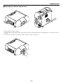
4. Reinstall the lens hood.
q Remove the front lens cap from the lens unit.
w Insert the lens hood so that the grooves on the 4 corners of the lens hood
are properly lined up with the 4 catches on the projector.
e Secure the 2 screws using the hexagonal driver.
This completes installation. If necessary, put the lens hood cap on the lens
hood.
AU
DIO
OU
T
RG
L/M
ON
O
AU
B1
DIO
DV
R
RG
AU
B2
L/M
ON
O
DIO
R/C
R
r
SL
OT
I
1
SL
OT
2
RG
B OU
T
G/Y
VIDE
O
S-VI
DE
B/C
O
b
H/H
V
L/M
ON
O
R
V
L/M
ON
O
R
AU
DIO
2
OU
T
US
B (MO
USE/H
UB)
US
B (PC
1
)
PC
RG
L/M
ON
O
AU
DIO
B1
PC
DV
R
RG
B2
L/M
ON
O
AU
DIO
R/C
r
R
SL
OT
2
IN
1
LA
N
SL
OT
2
RG
B OU
T
OU
T
SC
G/Y
VIDE
CA
RD
CO
NT
RO
L
I
RE
MO
TE
TR
IGGE
R
S-VI
DE
O
B/C
b
RE
MO
TE
OU
T
L/M
ON
O
R
2
IN
H/H
V
V
L/M
ON
O
AC
R
US
B (MO
USE/H
UB)
US
B (PC
1
)
PC
PC
CA
RD
CO
NT
RO
L
2
IN
LA
N
OU
T
SC
RE
MO
TE
TR
IGGE
R
RE
MO
TE
1
1
O
1
2
IN
OU
T
AC
IN
3
2-7
IN
2. Installation
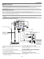
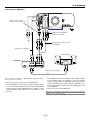
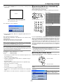
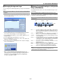
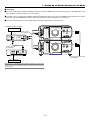
v Making Connections
NOTE: When using with a notebook PC, be sure to connect between the projector and the notebook PC before turning on the power to the notebook PC. In most cases
signal cannot be output from RGB output unless the notebook PC is turned on after connecting with the projector.
* If the screen goes blank while using your remote control, it may be the result of the computer's screen-saver or power management software.
* If you accidentally hit the POWER button on the remote control, wait 90 seconds (2 minutes in the optional extended life lamp) and then press the POWER
button again to resume.
When Viewing a DVI Digital Signal:
To project a DVI digital signal, be sure to connect the PC and the projector using a DVI-D signal cable (not supplied) before turning on your PC or
projector. Turn on the projector first and select DVI (DIGITAL) from the source menu before turning on your PC.
Failure to do so may not activate the digital output of the graphics card resulting in no picture being displayed. Should this happen, restart your PC.
Do not disconnect the DVI-D signal cable while the projector is running. If the signal cable has been disconnected and then re-connected, an image may
not be correctly displayed. Should this happen, restart your PC.
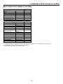
NOTE:
• Use the DVI-D cable compliant with DDWG (Digital Display Working Group) DVI (Digital Visual Interface) revision 1.0 standard. The DVI-D cable should be within 5 m
(196") long.
• The DVI (DIGITAL) connector accepts VGA (640x480), SVGA (800x600), 1152x864, XGA (1024x768) and SXGA (1280x1024 @ up to 60Hz).
Connecting Your PC or Macintosh Computer
DVI
AUDIO
RGB 1
AUDIO OUT
SLOT 1
SLOT 2
USB A
USB B
PC CARD
1
L/MONO
L/MONO
R
LAN
PC CONTROL
R
AUDIO
RGB 2
R/Cr
G/Y
RGB 2
2
DVI
RGB OUT
IN
RGB 1
REMOTE 1
OUT
B/Cb
VIDEO
SC TRIGGER
S-VIDEO
H/
HV
REMOTE 2
IN
OUT
V
L/MONO
R
AC IN
L/MONO
R
Audio cable (not supplied)
BNC⳯5 cable (not supplied)
Audio cable (not supplied)
IBM PC or Compatibles (Desktop type)
or Macintosh (Desktop type)
RGB signal cable
(not supplied)
To mini D-Sub 15-pin connector on the projector.
PHONE
DVI-D cable with ferrite core
(not supplied)
Audio cable (not supplied)
NOTE: For older
Macintosh, use a commercially available pin
adapter (not supplied)
to connect to your
Mac's video port.
PHONE
IBM VGA or Compatibles (Notebook type)
or Macintosh (Notebook type)
Connecting your PC or Macintosh computer to your projector will enable you to project your computer's screen image for an impressive presentation.
To connect to a PC or Macintosh, simply:
1. Turn off the power to your projector and computer.
2. Use a commercially available signal cable to connect your
PC or Macintosh to the projector.
Connecting to RGB 1 IN connectors (BNC)
Use a BNC⳯5 cable (not supplied) to connect your PC and the RGB 1
IN connectors on your projector.
Connecting to RGB2 IN connector (D-Sub 15 Pin)
Use an RGB signal cable (not supplied) to connect your PC and the
RGB2 IN connector on your projector.
3. Turn on the projector and the computer.
Connecting Your PC with a DVI Connector
4. If the projector goes blank after a period of inactivity, it may
be caused by a screen saver installed on the computer you've
connected to the projector.
Use a DVI-D signal cable (not supplied) to connect a DVI connector of
your PC to the projector.
2-8
2. Installation
To connect SCART output (RGB)
1. Turn off the power to the projector and your video equipment.
Before connections: An exclusive SCART adapter (ADP-SC1) and a
commercially available SCART cable are required for this connection.
2. Use the ADP-SC1 SCART adapter and a commercially
available SCART cable to connect the RGB 2 input of your
projector and a SCART output (RGB) of your video equipment.
NOTE:
• Audio signal is not available for this connection.
• The RGB 1 IN connector does not support Plug & Play.
3. Turn on the power to the projector and your video equipment.
4. Use the RGB 2 button on the remote control to select the RGB
2 input.
Projector
Video equipment
such as DVD player
AUDIO
5. Press the MENU button on the remote control to display the
menu.
2
DVI
RGB 1
AUDIO OUT
SLOT 1
SLOT 2
USB A
USB B
PC CARD
1
L/MONO
L/MONO
R
LAN
PC CONTROL
R
AUDIO
RGB 2
R/Cr
IN
REMOTE 1
G/Y
RGB OUT
OUT
RGB 2
B/Cb
VIDEO
SC TRIGGER
S-VIDEO
H/
HV
REMOTE 2
IN
OUT
6. From the Advanced menu, select [Projector Options] → [Setup]
→ [Page 3] → [Signal Select RGB2] → [Scart].
SCART is a standard European audio-visual connector for TVs,
VCRs and DVD players. It is also referred to as Euro-connector.
V
L/MONO
R
AC IN
L/MONO
R
To RGB 2 IN
Commercially available
SCART cable
Female
ADP-SC1
NOTE: The ADP-SC1 SCART adapter is obtainable from your dealer in Europe.
Contact your dealer in Europe for more information.
Connecting an External Monitor
AUDIO
DVI
RGB 1
AUDIO OUT
SLOT 1
SLOT 2
USB A
USB B
PC CARD
L/MONO
L/MONO
R
LAN
PC CONTROL
R
AUDIO
RGB 2
R/Cr
IN
REMOTE 1
G/Y
RGB OUT
OUT
B/Cb
VIDEO
SC TRIGGER
S-VIDEO
RGB OUT
H/
HV
REMOTE 2
IN
OUT
V
L/MONO
R
AC IN
L/MONO
R
Audio cable
(not supplied)
RGB signal cable
(not supplied)
To mini D-Sub 15-pin connector on the projector.
LINE IN
Audio cable
(not supplied)
RGB signal cable
(not supplied)
To mini D-Sub 15-pin connector on the projector.
PHONE
You can connect a separate, external monitor to your projector to simultaneously view on a monitor the RGB analog image you're projecting. To do
so:
1. Turn off the power to your projector, monitor and computer.
2. Use a 15-pin cable to connect your monitor to the RGB OUT
(Mini D-Sub 15 pin) connector on your projector.
3. Turn on the projector, monitor and the computer.
NOTE:
• The RGB OUT connector outputs RGB signal during idle mode (See page 8-15).
When the projector goes into idle mode, the image on an external monitor disappears for a moment. Note that the RGB OUT connector will not output RGB
signal during Standby mode.
• When the projector is in the Idle mode, the image may not be correctly displayed while the cooling fans are running immediately after turning on or off the
power. Note that the RGB OUT connector will not output RGB signal during
Standby mode.
• Daisy chain connection is not possible.
2-9
2. Installation
Connecting Your DVD Player
DVI
AUDIO
RGB 1
AUDIO OUT
SLOT 1
L/MONO
R
USB A
USB B
PC CARD
LAN
PC CONTROL
R
AUDIO
RGB 2
SLOT 2
RGB 1
L/MONO
R/Cr
IN
REMOTE 1
G/Y
RGB OUT
Optional 15-pin-to-RCA
(female)⳯3 cable (ADP-CV1)
RGB 2
OUT
B/Cb
VIDEO
SC TRIGGER
S-VIDEO
REMOTE 2
H/
HV
IN
OUT
V
L/MONO
R
AC IN
L/MONO
R
RCA(female)-to-BNC(male)
adapter (not supplied)
Component video RCA⳯3 cable
(not supplied)
Audio cable (not supplied)
Audio Equipment
DVD player
AUDIO IN
L
L
R
AUDIO OUT
Y
Cb
R
Cr
Component
Audio cable (not supplied)
For a DVD player without a component video (Y,Cb,Cr) output,
use an S-Video cable (not supplied) to connect an S-Video
output of the DVD player to the S-Video input of the projector.
Use an appropriate type of audio cable (not supplied) to connect the desired type of audio from your DVD player to your
audio equipment.
You can connect your projector to a DVD player with component output or
Video output. To do so, simply:
1. Turn off the power to your projector and DVD player.
2. If your DVD player has the component video (Y,Cb,Cr) output,
use a commercially available component video cable (RCAX3)
and the optional 15-pin-to-RCA (female)⳯3 cable to connect
your DVD player to the RGB 1 IN or 2 IN connector on the
projector.
3. Turn on the projector and DVD player.
NOTE: Refer to your DVD player's owner's manual for more information about your
DVD player's video output requirements,
2-10
2. Installation
Connecting Your VCR or Laser Disc Player
AUDIO
DVI
RGB 1
AUDIO OUT
SLOT 1
L/MONO
SLOT 2
USB A
USB B
PC CARD
L/MONO
R
RGB 2
LAN
PC CONTROL
R
AUDIO
R/Cr
IN
REMOTE 1
G/Y
RGB OUT
VIDEO
B/Cb
VIDEO
S-VIDEO
OUT
S-VIDEO
SC TRIGGER
H/
HV
REMOTE 2
IN
OUT
V
L/MONO
AC IN
L/MONO
R
R
Video cable (not supplied)
Audio cable (not supplied)
S-video cable (not supplied)
Audio equipment
VCR/ Laser disc player
AUDIO IN
L
L
R
AUDIO OUT
R
S-VIDEO VIDEO
VIDEO OUT
Audio cable (not supplied)
Use common RCA cables (not provided) to connect your VCR, laser disc
player or document camera to your projector.
To make these connections, simply:
1. Turn off the power to the projector and VCR, laser disc player
or document camera.
NOTE: Refer to your VCR or laser disc player owner's manual for more information
about your equipment's video output requirements.
NOTE: An image may not be displayed correctly when a Video or S-Video source is
played back in fast-forward or fast-rewind via a scan converter.
2. Connect one end of an RCA cable (not supplied) to the video
output connector on the back of your VCR or laser disc player,
connect the other end to the Video input on your projector (an
RCA to BNC adapter is necessary). Use an audio cable (not
supplied) to connect the audio from your VCR or laser disc
player to your audio equipment (if your VCR or laser disc player
has this capability). Be careful to keep your right and left channel connections correct for stereo sound.
3. Turn on the projector and the VCR or laser disc player.
2-11
2. Installation
Connecting to a Network
With the LAN connection, you can control the projector over the network using a computer to switch the unit on/off, select the input and others.
* To control the projector over the network using a computer, use the Dynamic Image Utility 2.0 contained on the User Supportware CD-ROM or the
HTTP Server feature.
* With the Image Express Utility 1.0 contained on the supplied User Supportware CD-ROM, you can project your PC screen image to the projector
over the network.
* With a use of the supplied User Supportware CD-ROM and the optional wireless LAN card (SWL-2100-N*), you can control the projector wirelessly
or send your PC screen image to the projector over the network using a computer.
Example of LAN connection
Server
Hub
LAN cable (not supplied)
AUDIO
2
DVI
RGB 1
AUDIO OUT
OPTION 1
L/MONO
OPTION 2
USB (MOUSE/HUB) USB (PC)
LAN
1
PC CARD
L/MONO
R
R
AUDIO
RGB 2
LAN
PC CONTROL
R/Cr
IN
REMOTE 1
G/Y
RGB OUT
OUT
B/Cb
VIDEO
S-VIDEO
H/HV
SC TRIGGER
REMOTE 2
IN
OUT
V
L/MONO
L/MONO
R
R
AC IN
Using the HTTP Server function
Using the User Supportware
1. Configure your LAN settings such as IP address on the projector. (See “LAN Mode” on page 8-19)
1. Configure your LAN settings such as IP address on the projector. (See “LAN Mode” on page 8-19)
2. Start the Web browser on the computer connected to the network and execute HTTP server functions. (See “Operation
Using an HTTP Browser” on page 10-11)
2. Install the software contained on the User Supportware CDROM into the computer connected to the network. See “6 Using the Projector in a Network” on page 6-1.
2-12
2. Installation
Connecting the Supplied Power Cable
Connect the supplied power cable to the projector.
First connect the supplied power cable's three-pin plug to the AC IN of the projector, and then connect the other plug of the supplied power cable in the
wall outlet.
AU
DIO
OU
T
RG
L/M
ON
O
AU
B1
DIO
DV
R
RG
AU
B2
L/M
ON
O
DIO
R/C
R
r
SL
OT
I
1
SL
OT
2
RG
B OU
T
G/Y
VIDE
O
S-VI
DE
B/C
O
b
H/H
V
L/M
ON
O
R
V
L/M
ON
O
R
US
B (MO
USE/H
UB)
US
B (PC
2
)
PC
PC
CA
RD
CO
NT
RO
L
1
IN
LA
N
OU
T
SC
RE
MO
TE
TR
IGGE
R
RE
MO
TE
1
2
IN
OU
T
AC
2-13
IN
3
Projecting an Image
(Basic Operation)
○ ○ ○ ○ ○ ○ ○ ○ ○ ○ ○ ○ ○ ○ ○ ○ ○ ○ ○ ○ ○ ○ ○ ○ ○ ○ ○ ○ ○ ○ ○ ○ ○ ○ ○ ○ ○ ○ ○ ○
z Turning on the Projector............................................ 3-2
x Selecting a Source ................................................... 3-3
c Adjusting the Picture Size and Position .................... 3-3
v Correcting the Horizontal and
Vertical Keystone Distortion (3D Reform) ................ 3-4
b Optimizing RGB Picture Automatically ..................... 3-6
n Turning Up or Down Volume ..................................... 3-6
m Turning off the Projector............................................ 3-7
3. Projecting an Image
This chapter describes how to turn on the projector and to project a picture onto the screen.
2. Press the ENTER button to execute the selection.
z Turning on the Projector
MENU
3D
L
NT
A
3D REFORM AUTO ADJUST
SELECT
E
NOTE:
• When plugging in or unplugging the supplied power cable, make sure that the
main power switch is pushed to the off[O] position. Failure to do so may cause
damage to the projector.
• The projector has two power switches: main power switch and POWER button
(POWER ON and OFF on the remote control)
• The projector has a feature to prevent itself from being used by unauthorized
individuals. To use this feature, register your PC card as a protect key. See "Security" in "Projector Options" on page 8-23 for more details.
ER
CAN
LAMP 2
CE
STATUS
ON/STAND BY
POWER
3. The Basic menu will be displayed in the language you have selected.
To turn on the main power to the projector,
press the Main Power switch to the ON position ( I ).
Flashing for 1
Steady light
minute.
Standby or Idle
POWER
POWER
Flashing green
light
Steady green
light
POWER
ON/STAND BY
Steady orange
light
Before you turn on your projector, ensure that the computer or video source
is turned on and that your lens hood cap is removed.
Only after you press the ON/STAND BY button on the projector cabinet or
POWER ON button on the remote control for a minimum of 2 seconds will
the power indicator turn to green and the projector become ready to use.
To close the menu, press the CANCEL button.
MENU
MENU
3D
3D
E
NT
L
3D REFORM AUTO ADJUST
SELECT
ER
CAN
CE
ON/STAND BY
L
E
NT
A
3D REFORM AUTO ADJUST
SELECT
A
ER
CA
LAMP 2
E
NC
ON/STAND BY
LAMP 2
NOTE: You cannot turn off the projector for 60 seconds immediately after turning
on the projector.
Note on Startup screen (Menu Language Select screen)
When you first turn on the projector, you will get the Startup screen. This
screen gives you the opportunity to select one of the seven menu languages: English, German, French, Italian, Spanish, Swedish and Japanese.
To select a menu language, follow these steps:
1. Use the SELECT 왖 or 왔 button to select one of the seven languages
for the menu.
MENU
LAMP 2
CAN
CE
STATUS
After this has been done, you can proceed to the advanced menu operation.
If you want, you can select the menu language later. See "Language" on
page 8-13.
NOTE: To turn the projector on by plugging in the power cable, first turn on the
Main Power switch to ON and use the menu and enable the "Auto Start" feature.
(See page 8-16.) Immediately after turning on the projector, screen flicker may
occur. This is not a fault. Wait 3 to 5 minutes until the lamp lighting is stabilized.
• If one of the following things happens, the projector will not turn on.
* If the internal temperature of the projector is too high, the projector
detects abnormal high temperature. In this condition the projector will
not turn on to protect the internal system. If this happens, wait for the
projector's internal components to cool down.
* When the lamp reaches its end of usable life, the projector will not turn
on. If this happens, replace the lamp.
ON/STAND BY
* If the lamp fails to light, and if the LAMP indicator 1 or 2 flashes on and
off in a cycle of six times, wait a full minute and then turn on the power.
L
E
ER
POWER
3D REFORM AUTO ADJUST
3D
SELECT
NT
STATUS
POWER
STATUS
A
POWER
3-2
3. Projecting an Image
x Selecting a Source
c Adjusting the Picture Size and Position
Selecting the computer or video source
1. Turn on the projector
2. Select your type of projector orientation.
Desktop front, ceiling rear, desktop rear, and ceiling front.
Using the Remote Control
POWER
OFF
Press the Source/Number button (0-9) to select input.
ON
MENU
-
BS
ADDRESS
+
ENTER
1 ...... RGB 1 input
2 ...... RGB 2 input
ADJUST
3 ...... DVI (DIGITAL) input
IMAGE
PICTURE WHITE BAL. PROJECTOR
ABC
DEF
GHI
1
2
3
JKL
MNO
PQR
4
5
6
STU
VWX
YZ /
4 ...... VIDEO input
5 ...... S-VIDEO input
6 ...... Viewer
7 ...... LAN
7
8
9
,.
UNDO
CANCEL
3. Display the test pattern by pressing the TEST button on the remote
control or using the menu.
8 ...... SLOT 1
0
9 ...... SLOT 2
TEST
INFO.
HELP
POSITION PIXEL
AUTO
0 ...... Sequentially selects:
RGB1 (VIDEO) → RGB2 (S-VIDEO) →
LENS
MUTE
SHUTTER
TEST
RGB1 (VIDEO) ........
PICTURE SOUND
OSD
KEYSTONE AMPLITUDE ENTRYLIST
R
G
B
MAGNIFY
+
+
-
-
FOCUS
ZOOM
LENS
4. Adjust the image position and the image size.
CTL
(1) Press and hold the CTL button and press the POSITION button to
display the Lens Shift adjustment screen.
NOTE: If no input signal is available, the projector will display a blue background
(factory preset).
Use the SELECT button on the remote control or the LENS SHIFT
button on the projector cabinet to move the image horizontally and
vertically.
To close the Lens Shift adjustment screen, press the CANCEL
button. See pages 2-4 and 2-5 for “Lens Shift Adjustable Range”.
Using the menu
You can also select the computer or video source using the menu.
POSITION
LENS
POWER
OFF
ON
MENU
3D
BS
-
+
CTL
ADDRESS
ENTER
L
E
NT
MENU
A
3D REFORM AUTO ADJUST
SELECT
ER
LAMP 2
CAN
CE
STATUS
ON/STAND BY
POWER
-
3-3
+
3. Projecting an Image
(2) Press and hold the CTL and press the ZOOM + or - button to adjust
the image size. You can also adjust the image size by using the
ZOOM + or - button on the projector cabinet.
Preparation (Recommended):
Warm up the projector for about 60 minutes.
Adjusting the Focus
MAGNIFY
+
+
-
-
FOCUS
1. Practice focusing
Use the FOCUS (+) or (-) button on the projector or the remote control
to increase or decrease the focus values to verify the accuracy of focusing.
2. Try optimizing defocus
Use the FOCUS button (-) to decrease the focus values until pixel patterns are too blurry to be visible.
ZOOM
LENS
3. Obtain correct focus
Use the FOCUS button (+) to obtain the best focus. Do not use the
FOCUS (-) button at this time.
Finally store the adjustments in memory.
If you adjust beyond the best focus point, go back to step 2 and repeat
the procedures. Always adjust the focus from the negative direction
towards the positive direction.
CTL
Geometric Correction Tool
If you use a special shaped screen such as a cylindrical or spherical
screen, a downloadable program, Geometric Correction Tool is available. This program (Geometric Correction Tool) enables the geometrical distortion correction of an image when projected onto a special
shaped screen with a projector. Additionally, this program allows control of the projector via a computer.
For additional information visit:
US : http://www.necvisualsystems.com
Europe : http://www.nec-europe.com/
Global : http://www.nec-pj.com/
(3) Press and hold the CTL button and press the FOCUS + or - button
to obtain the best focus. You can also adjust the focus by using the
FOCUS + or - button on the projector cabinet.
MAGNIFY
+
+
-
-
FOCUS
v Correcting the Horizontal and Vertical
Keystone Distortion (3D Reform)
ZOOM
LENS
Use the 3D Reform feature to correct keystone (trapezoidal) distortion to
make the top or bottom and the left or right side of the screen longer or
shorter so that the projected image is rectangular.
In the following description, 3D Reform (Cornerstone) correction can be
done with the USB mouse, remote control or cabinet buttons.
CTL
When using the USB mouse connected to the projector
Preparation: Connect the USB mouse to the projector. See page 4-3.
1. Project an image so that the screen is smaller than the area of the
raster.
2. Pick up any one of the corners and align the corner of the screen with
the one of the image. (The drawing shows the upper right corner.)
Tips on Adjusting Focus
Optimum focus adjustments can be achieved on the projector by
paying special attention in a few areas.
Focus adjustment after the projector has warned up to normal
operating temperature is better than doing so when the projector
is cold.
Lens mechanism interacts differently when adjusting focus from
one direction to the other.
For this reason final focus adjustments should be done in a specific direction.
For optimum focus, follow the steps below.
For the zoom and the lens shift adjustment, perform the normal
procedures.
3-4
Projected image
Screen
3. Projecting an Image
3. Press the 3D REFORM button on the remote control.
The Cornerstone adjustment screen is displayed.
The Cornerstone adjustment screen will disappear when you move the
USB mouse cursor.
When using the remote control or cabinet buttons:
4. Point to one of the remaining 3 corners and left-click on it.
2. Pick up any one of the corners and align the corner of the screen with
the one of the image.
Projected image
Left-click on the corner.
1. Project an image so that the screen is smaller than the area of the
raster.
Screen
Screen
(The drawing shows the upper right corner.)
5. Do the above step 4 for the other two corners so that the projected area
becomes smaller than the screen.
3. Press the 3D REFORM button on the projector or the KEYSTONE button on the remote control.
Screen
The Cornerstone adjustment screen is displayed.
NOTE: Press the 3D REFORM button to toggle between "Cornerstone" and "Keystone."
Left-click on each corner.
4. Use the SELECT 왖왔왗왘 button to select one icon which points in the
direction you wish to move the projected image frame.
6. To complete the procedure, right-click anywhere on the screen.
The confirmation screen is displayed.
7. Left-click on "OK".
This completes the Cornerstone adjustment.
* To return the Cornerstone adjustment to the default settings, left-click
on "Reset" in Step 7.
You can save your Cornerstone changes. The changes are saved when
you turn off the projector. To do so, select [Projector Options] → [Setup] →
[Page 4]. Select the 3D Reform Save check box. This is not selected at the
time of shipment.
* There are limitations of shapes which can be corrected using the Cornerstone adjustment.
When adjusting the Cornerstone beyond these limits, you will get the message "Out of adjustment range!" and no correction can be done. Should
this happen, do the Cornerstone adjustment again within the allowable
range.
* Due to limitations of accuracy within internal processes, there may be
some discrepancy of positions between the mouse cursor and corrected
shape or one corner and the other 3 corners.
Screen
5. Press the ENTER button.
6. Use the SELECT 왖왔왗왘 button to move the projected image frame as
shown on the example.
7. Press the ENTER button.
Screen
3-5
3. Projecting an Image
8. Use the SELECT 왖왔왗왘 button to select another icon which points in
the direction.
b Optimizing RGB Picture Automatically
Adjusting the Image Using Auto Adjust
Optimizing RGB image automatically
Press the Auto Adjust button to optimize an RGB image automatically.
[Poor picture]
MENU
Screen
3D
L
E
NT
On the Cornerstone adjustment screen, select
“Exit” and then “OK”, or press the CANCEL button on the remote control.
A
3D REFORM AUTO ADJUST
SELECT
ER
LAMP 2
CAN
CE
STATUS
The confirmation screen is displayed.
ON/STAND BY
POWER
JKL
MNO
4
5
PQR
6
STU
VWX
YZ /
7
8
9
,.
UNDO
CANCEL
INFO.
HELP
POSITION PIXEL
AUTO
[Normal picture]
0
TEST
LENS
9. Press the SELECT 왗 or 왘 button to highlight the [OK] and press the
ENTER button.
This completes the keystone correction.
Selecting “Cancel” will return to the adjustment screen without saving
changes (Step 3).
Selecting "Reset" will return to the factory default.
Selecting "Undo" will exit without saving changes.
NOTE: To return the 3D Reform correction setting values to the factory default,
press and hold the 3D REFORM button on the projector cabinet or the KEYSTONE
button on the remote control for a minimum of 2 seconds.
NOTE: During 3D Reform adjustment, "Aspect Ratio" and "Screen" may not be available. Should this happen, first reset the 3D Reform data and then do each setting.
Second repeat the 3D Reform adjustment. Changing Aspect Ratio and/or Screen
setting can limit 3D Reform in its adjustable range.
The adjustable ranges for 3D Reform are as follows:
Horizontal ........... Max ±30° approx.
Vertical ............... Max ±40° approx.
Press the AUTO ADJUST or AUTO button to fine-tune the computer image or to remove any vertical banding that might appear and to reduce
video noise, dot interference or cross talk (this is evident when part of your
image appears to be shimmering). This function adjusts the clock frequencies that eliminate the horizontal banding in the image. This function also
adjusts the clock phase to reduce video noise, dot interference or cross
talk. (This is evident when part of your image appears to be shimmering.)
This adjustment may be necessary when you connect your computer for
the first time.
NOTE:
• Some signals may not be displayed correctly or take time.
• The Auto Adjust function does not work for component and video signal.
• If the Auto Adjust operation cannot optimize the RGB signal, try to adjust Clock
and Phase manually. See page 8-10.
n Turning Up or Down Volume
* The following are conditions at the above maximum angle when all of
the following are met
Sound level from the speaker and the AUDIO OUT jack (RCA) on the
projector can be adjusted.
• Image is projected in Wide (Zoom)
• The lens is positioned at the center (when not, adjustable range increases or decreases)
-
+
increase volume
• Resolution is XGA
Higher resolution than XGA limits 3D Reform in its adjustable range.
• Menu items should be set as follows:
decrease volume
Aspect Ratio ............................... 1.33:1 (4:3)
NOTE: The SELECT 왖 or 왔 button works as a volume control only when no menu
appears.
Screen Type ................................ 1.33:1 (4:3)
• Horizontal and Vertical are adjusted separately.
A combination of both adjustments limits 3D Reform in its adjustable
range.
Volume bar
• When “Native” is selected in “Resolution”, “3D Reform” is not available.
3-6
NOTE: The volume bar can be displayed by selecting “Sound” from “Basic Menu” or “Advanced Menu”.
3. Projecting an Image
m Turning off the Projector
To turn off the projector:
First press the POWER (ON/STAND BY) button on the projector cabinet
or the POWER OFF button on the remote control for a minimum of two
seconds. The POWER indicator will glow orange. After the projector turns
off, the cooling fans keep operating for 90 seconds (2 minutes in the optional extended life lamp) (Cooling-off time).
Second, turn off the Main Power switch. The power indicator will go out.
Last unplug the power cable.
POWER
OFF
ON
MENU
BS
-
+
ADDRESS
ENTER
Fan working
Power on
POWER
POWER
Standby or Idle
POWER
ON/STAND BY
Steady green
light
Flashing orange Steady orange
light
light
NOTE: You cannot turn off the projector for 1 minute immediately after turning on
the projector.
CAUTION
Do not unplug the power cable from the wall outlet or do not turn off
the main power under any one of the following circumstances. Doing
so can cause damage to the projector:
• While the Hour Glass icon appears.
• While the message "Please wait a moment." appears. This message will be displayed after the projector is turned off.
• While the cooling fans are running. (The cooling fans continue to
work for 90 seconds (2 minutes in the optional extended life lamp)
after the projector is turned off).
• While accessing a PC card or LAN card. (The PC Card Access indicator lights.)
3-7
4
Convenient Features
○ ○ ○ ○ ○ ○ ○ ○ ○ ○ ○ ○ ○ ○ ○ ○ ○ ○ ○ ○ ○ ○ ○ ○ ○ ○ ○ ○ ○ ○ ○ ○ ○ ○ ○ ○ ○ ○ ○ ○
z Turning Off the Image and Sound ............................. 4-2
x Enlarging and Moving a Picture ................................ 4-2
c Getting the On-line Help and Information ................. 4-2
v Using a USB Mouse ................................................. 4-3
b Using a USB HUB Function ...................................... 4-3
n Changing Background Logo ..................................... 4-4
m Making Freehand Drawings on
a Projected Image (ChalkBoard) .............................. 4-4
, Lens Memory ............................................................ 4-5
4. Convenient Features
z Turning Off the Image and Sound
x Enlarging and Moving a Picture
Press the MUTE PICTURE button to turn off the image and sound for a
short period of time. Press again to restore the image and sound.
You can enlarge the area you want up to 400 percent.
To do so:
Press the MAGNIFY button.
MUTE
PICTURE
SOUND
OSD
Press the MUTE SOUND button to turn off the sound for a short period of
time. Press again to restore the sound.
Enlarge the selected area.
When the MAGNIFY (+) button is pressed, the image is magnified. To
move the magnified image, use the SELECT button.
MUTE
PICTURE
SOUND
MAGNIFY
OSD
+
-
Press the MUTE OSD button to turn off the on-screen display. Press again
to restore the on-screen display.
ZOOM
Return the image to the original size.
MUTE
PICTURE
SOUND
MAGNIFY
OSD
+
-
NOTE: You can also turn off the on-screen display forcibly by pressing and holding
CTL and then pressing MUTE OSD (Forced On-Screen Mute Mode) ; doing this
again restores it. In this case any adjustment will still change the projector's memory
settings. This mode is available even when input is switched to another or the main
power is turned off.
ZOOM
c Getting the On-line Help and Information
You get the contents about Help.
HELP
SELECT
Display Help
Exit Help
You get the source and projector information.
INFO.
Press this button once to display “Source Information” and press twice to
display “Projector Information”.
Press third time to close it.
4-2
4. Convenient Features
v Using the USB Mouse
Operate the PC mouse using the USB mouse
USB(PC)
Using a commercially available USB mouse gives you smooth operation.
AUDIO
OPTION 1
R
USB(MOUSE/HUB)
OPTION 2
USB (MOUSE/HUB) USB (PC)
1
PC CARD
L/MONO
L/MONO
AUDIO
2
DVI
RGB 1
AUDIO OUT
LAN
PC CONTROL
R
AUDIO
RGB 2
R/Cr
IN
REMOTE 1
G/Y
RGB OUT
2
DVI
OUT
B/Cb
RGB 1
AUDIO OUT
OPTION 1
OPTION 2
VIDEO
USB (MOUSE/HUB) USB (PC)
SC TRIGGER
S-VIDEO
REMOTE 2
1
PC CARD
IN
H/HV
L/MONO
OUT
L/MONO
R
RGB 2
LAN
PC CONTROL
R
AUDIO
V
L/MONO
L/MONO
R
R
AC IN
R/Cr
IN
REMOTE 1
G/Y
RGB OUT
OUT
B/Cb
VIDEO
SC TRIGGER
S-VIDEO
REMOTE 2
IN
H/HV
OUT
V
L/MONO
L/MONO
R
R
AC IN
NOTE: You can select the operation mode of the USB mouse connected to the USB
port of the projector.
NOTE: There may be some brands of USB mouse that the projector does not support.
b Using the USB HUB Function
Operate the Projector Menus using the USB mouse
Mouse Cursor
When connecting a USB mouse to the projector, you get a
mouse cursor on the screen.
Unless you use your USB mouse within 10 seconds, the mouse
cursor disappears.
When using the projector with a PC via the supplied USB cable, both the
USB port(type A) on the projector can be connected to a USB-supported
scanner or other USB-supported device. (USB Hub Function)
Example: When connecting a PC and a scanner to each USB port respectively
Menu Display
Clicking with a mouse button displays the menu.
Clicking 왘 displays the pull-down menu. To close the menu,
click anywhere in the background.
USB(MOUSE/HUB)
AUDIO
USB(PC)
2
DVI
RGB 1
AUDIO OUT
OPTION 1
L/MONO
OPTION 2
USB (MOUSE/HUB) USB (PC)
1
PC CARD
L/MONO
R
R
AUDIO
RGB 2
LAN
PC CONTROL
R/Cr
IN
REMOTE 1
G/Y
RGB OUT
OUT
B/Cb
VIDEO
S-VIDEO
H/HV
SC TRIGGER
REMOTE 2
IN
OUT
V
Adjusting and Setting Display
L/MONO
L/MONO
R
R
AC IN
You can select a menu item and click with a mouse button to
make adjustments and setting.
Examples
Click (or press and hold) the mouse button 왗 or 왘 to adjust
the brightness. Or click and drag the mouse button on the slide
bar horizontally to adjust it.
An example of how a scanned image is projected
To save the adjustments, click
. This closes the menu. If you
click anywhere in the background while displaying an adjustment and setting menu or dialog box, you will go to the main
menu after clicking with the mouse.
1. Install the Dynamic Image Utility on your PC.
Clicking
2. Use your scanner to scan an image.
displays help.
NOTE: The Dynamic Image Utility is contained on the supplied CD-ROM. See
“6- b Software Installation” for the installation procedure.
NOTE: A scanner driver must be installed on your PC before use.
Using the Middle Button/Wheel on a Mouse (when available)
The projector supports the middle button/wheel on a mouse. With
the middle button/wheel you can use a scroll bar or click the middle
button/wheel to display or hide the Chalkboard toolbar.
3. Load the scanned image on your PC using the Dynamic Image Utility.
4. Transmit the scanned image from your PC to the projector via the USB
cable and project the image on the screen.
NOTE:
• The USB HUB function is effective only when “Auto” is selected in Operation
Mode Select.
• The PCs using the USB Host Controller may not be available.
• When connecting a USB hub to the USB port (type B) on the projector, be sure
to use a USB hub capable of supplying 500mA per port of downstream current.
4-3
4. Convenient Features
n Changing Background Logo
You can change the default background logo using the PC Card Files
feature.
NOTE: File size must be 256KB or less. Other file formats than JPEG and BMP are
not available.
1. From the menu, select [Tools] → [PC Card Files] to display a list of all
the files stored in the PC card so that you can select a file you want to
use as a background logo.
m Making Freehand Drawings on a Projected
Image (ChalkBoard)
The ChalkBoard feature allows you to write and draw messages on a projected image.
NOTE: The ChalkBoard feature is available only when a USB mouse is used.
From the menu, select [Tools] → [ChalkBoard] to display the ChalkBoard
tool bar that contains the following icons.
NOTE: You can also display the ChalkBoard tool bar by clicking the scroll button on
your USB mouse.
Pen
Eraser
Drive
Exit
Color
2. The Logo button allows you to select a background logo from graphic
files on a PC card and change to it as the background logo.
3. Use the SELECT 왖 or 왔 button to select a JPEG or BMP file for your
background logo.
4. Use the SELECT 왘 and then 왔 button to select "Logo".
5. Press the ENTER button on the remote control or the cabinet. You
will get the confirmation dialog box.
6. Select "OK" and press the ENTER button. This completes changing
a logo for the background.
Capture
Clear
Hide
Pen .............. Left-click and drag to draw. Left-click [왖] or right-click the
pen icon to display the pen palette containing four lines of
different thickness from which you can select a line you prefer by left-clicking.
Color ........... Selects a color. Left-click to display the color palette from
which you can select a color you prefer by left-clicking.
Capture ....... Left click to capture and save freehand drawings in the PC
card. (GT5000 only)
Eraser ......... Left-click and drag to erase part of a drawing. Left-click [왖]
or right-click the eraser icon to display the eraser palette
containing four eraser of different thickness from which you
can select an eraser you prefer by left-clicking.
Clear ........... Left-click to clear the drawing completely from the
ChalkBoard screen.
Drive ............ Switches between PC Card slot. (GT5000 only)
Hide ............. Hides the tool bar by left-clicking. Right-clicking anywhere
on the screen displays the ChalkBoard tool bar again.
Exit .............. Clears the complete drawing and exits the ChalkBoard.
NOTE:
• The menu is not available while you display the ChalkBoard screen.
• Switching slides clears a drawing completely.
* Once you have changed the background from the logo to another, you cannot return the logo to background even by using Factory Default. To do so, repeat the above steps. The logo file is
included on the supplied CD-ROM Projector User Supportware
(“/Logo/nec_bb_x.jpg” for 9060.
4-4
4. Convenient Features
, Lens Memory
This function serves to store the adjusted value when using the Shift, Focus, and
Zoom buttons of the projector or the remote control.
Reference memory:
Reference Point ....... Adjusted settings are stored in memory as a reference common to all the input sources. If no setting is stored in Custom Point, the adjusted settings in Reference Point will be
applied.
Custom memory:
Custom Point ........... Adjusted settings are stored in memory for each input signal.
Usage Example
When you wish to display on a screen having a 4:3 aspect ratio an NTSC or other
4:3 aspect ratio signal and an SXGA or other 5:4 aspect ratio signal:
Perform shift, focus, and zoom adjustments to set the vertical screen size of the
vertically tall 5:4 aspect ratio signal to standard.
Both 4:3 apsect ratio signals and 5:4 aspect ratio signals can now be displayed.
Note that with these shift, focus, and zoom adjustments, the 4:3 aspect ratio signal
will become smaller on the screen.
To eliminate this size reduction, adjust the shift, focus and zoom to the optimum
condition for each of the 4:3 aspect ratio signal and the 5:4 aspect ratio signal.
Memory (storage) of each of these values will permit projection at an optimum condition upon signal switching.
1. Perform Zoom, Focus and Lens Shift adjustments and store them in memory
using “Set Custom Point”.
Another way to store your adjustments is to use the CTL and INFO buttons on
the remote control.
2. When “Yes” is selected for “Use Point on Signal Change”, the adjustment is applied to the signal you switched.
3. Select “OK” and press the ENTER button for the change to take effect.
NOTE: The Lens Memory function is not available in Link mode.
NOTE: The other optional lenses than GT10RLB, GT13ZLB, GT20ZL, GT24ZLB and GT34ZLB do not support
Lens Memory function. (On GT10RLB focus can be stored in memory)
You cannot store settings for zoom and focus on the following lenses:
GT13ZL, GT19ZL, GT24ZL and GT34ZL.
Picture Mute during Lens Shift?
To turn off the image and sound during lens shift, select "Yes".
NOTE: This option is only available when "Yes" is selected for "Use Point on Signal Change?".
4-5
5
Using the Viewer
○ ○ ○ ○ ○ ○ ○ ○ ○ ○ ○ ○ ○ ○ ○ ○ ○ ○ ○ ○ ○ ○ ○ ○ ○ ○ ○ ○ ○ ○ ○ ○ ○ ○ ○ ○ ○ ○ ○ ○
z Making the Most out of the Viewer Function ............. 5-2
x Operating the Viewer Function from the Projector
(playback) ................................................................. 5-3
5-1
5. Using the Viewer
NOTE:
• To use the Viewer, first you need to create presentation materials on your PC
using the Dynamic Image Utility 2.0 contained on the supplied Projector
User Supportware CD-ROM. For installation, see “6- b Software Installation”.
For creating presentation materials, see the Slide show function on the on-line
manual of the Dynamic Image Utility 2.0.
• Selecting Viewer sets the audio input for DVI input.
Inserting and Removing a PC Card
z Making the Most out of the Viewer Function
NOTE: When using two PC cards, do not insert both PC cards into the two PC card
slots simultaneously. Doing so may cause projector malfunction such as shutting
down. Each PC card must be inserted slowly one at a time.
Features
You can view presentation data, capture (9060), and play
images on the projector. A PC card is used to view presentation
data prepared on the computer and to capture and play images
projected with the projector.
The Viewer feature allows you to view slides stored on a PC
memory card (referred to as PC card in this manual) on the projector. Even if no computer is available, presentations can be
conducted simply with the projector. This feature is convenient
for holding presentations at meetings and in offices, as well as
for playing images taken on digital cameras.
NOTE:
• Do not try to force the PC card into the slot.
2
PC CARD
1
Inserting the PC Card
•
Hold the PC card horizontally and insert it slowly into PC card slot
1 or 2 with its top facing up.
PC card (not supplied)
US
B (MO
USE/H
UB)
US
B (PC
2
)
PC
PC
CA
RD
CO
NT
RO
L
1
IN
LA
N
OU
T
SC
RE
MOT
E1
TR
IGGE
R
RE
MOT
E2
Easy to use
IN
OU
T
•
Presentations can be started immediately simply by inserting a
PC card (not supplied)
•
Easy slide switching
•
Remote control operation
•
Jumping to list of slides or any specific slide
AC
IN
Removing the PC Card
Press the eject button slowly. The eject button card pops out a
little. Press the eject button slowly again. Grasp the edges of
the PC card and pull it out. Push and insert the eject button
fully until it stops.
High quality images
•
High resolution up to 1024 x 768 dots
•
24-bit full color playback
•
Viewing of digital camera images
US
B (MO
USE/H
UB)
Eject button
US
B (PC
2
)
PC
PC
CA
RD
CO
NT
RO
L
1
IN
LA
N
Simple utility software (for computer)
OU
T
SC
•
Dynamic Image Utility 2.0 operable on Windows 98/Me/XP/2000
•
Slides can be created by capturing the currently displayed image
RE
MOT
E1
TR
IGGE
R
RE
MOT
E2
IN
•
Control screen for displaying lists of slides and editing
*
Microsoft, Windows and PowerPoint are registered trademarks of
Microsoft Corporation.
OU
T
AC
IN
NOTE: Do not eject the PC card while its data is being accessed.
CAUTION: Make sure that the PC card or LAN card is removed
during Standby mode (NOT Idle mode)or with the main power
off.Failure to do so may cause damage to the data on your PC
card or LAN card,or may cause the projector to
malfunction.Should a malfunction occur, turn off the main power
and turn it back on.
Direction for Inserting the PC Card
The PC card has a top and bottom and must be inserted into the
PC card slot in a specific direction. It cannot be inserted backwards or upside-down. Attempting to force it into the slot in the
wrong direction may break the internal pin and damage the card
slot. Refer to the PC card's operating instructions for the proper
direction of insertion.
PC Card Type
The PC Card slot accepts PCMCIA Type II only.
5-2
5. Using the Viewer
x Operating the Viewer Function from the
Projector (playback)
When the tool bar is not displayed:
You can use the 왗 and 왘 button on the cabinet to select folders
or slides.
This section describes the operation for showing slides of presentation documents created using the Viewer function with the
projector. It is also possible to make slides directly from the images projected with the projector.
MENU
3D
E
L
NT
Projecting slides (Viewer)
1. Insert a PC card into the PC card slot.
A
3D REFORM AUTO ADJUST
SELECT
ER
LAMP 2
CAN
CE
STATUS
ON/STAND BY
POWER
Insert the PC card so that the end with the insertion direction arrow on
the top goes in first.
* Press the eject button to eject the card.
Multi cursor (blue marks)
2. Select the "Viewer" from the Source Select menu.
3. Project slides.
Folder
Checking "Show Folder List", means that selecting Viewer input
displays a list of the folders in the PC card and if "Auto Play" is
checked the projector automatically starts to play slides at the
first slide of the folder you have selected.
Folder
Current folder number
A tool bar will appear when you press the MENU button on the
remote control or the projector cabinet or clicking with the right
button of a mouse.
Prev
Play
Jump
Folder
Folder
Folder
02 : 0001 / 0008
Current slide
number
Number of all slides in folder
Delete
Drive
Use the SELECT 왗 or 왘 button to advance to the next folder
or return to the previous folder.
Next
Stop
Select
Setup
View
MENU
Folder
3D
The tool bar includes the following buttons:
3D REFORM
E
NT
L
SELECT
Prev .......... Returns to the previous slide or folder. Or this lets
you play slides back in reverse.
ER
LAMP 2
CAN
CE
STATUS
ON/STAND BY
POWER
Next .......... Advances to the next slide or folder. Or this lets you
play slides back.
Play .......... Plays back automatically or manually depending on
the setting on Viewer Options of the menu. This allows you to move on to the next slide when "Manual
Play" is selected.
Use the SELECT 왗 or 왘 button to advance to the next slide or
return to the previous slide.
Stop .......... This allows you to stop Auto Play while you are playing back and to resume playing from the selected
slide or folder when "Auto Play" is selected.
Slide(Table) cursor
(green marks)
Slide
Slide
Slide
Slide
Slide
Slide
Slide
Slide
Jump ........ Displays a list of slides while you are playing back.
Select ....... Displays a list of folders while you are playing back.
Drive ......... Switches between PC Card slot.
Setup ........ Displays the Viewer Options dialog box on Page 2 of
the Setup dialog box.
Delete ....... Deletes a captured slide(s) or all the captured slides
in the Capture - specific folder. (9060)
View ......... Hides the tool bar while you are playing back. Pressing the MENU button or clicking with the right button
of a mouse shows it again.
NOTE: If no memory card is inserted in the PC CARD slot, there is no signal, and a
black, blue or logo background is displayed, depending on the setting.
Playback is stopped when 왗왘 button on the cabinet is pressed in Auto Play mode.
Up to 12 indexes can be displayed on the list of folders. The folder in the right
bottom is always a folder exclusively for captured images, but is only displayed
when images have been captured. (9060 only)
5-3
02 : 0004 / 0008
5. Using the Viewer
If the "Auto Play" option is selected in "Viewer Options" of the
menu, any given slide will start to play automatically.
You can also specify Auto Play Interval between 5 and 300 seconds.
Preparations:
Insert the PC card into the card slot.
Insert the PC card so that the end with the insertion direction
arrow on the top goes in first.
* Press the eject button to eject the card.
Switching to Slides Directly from Other Input Modes
1. Project the image you wish to store on the projector.
Auto Play Mode
With this function it is possible to switch directly to a slide when
the picture of a VCR or computer is being projected.
Example: When conducting presentations using a combination
of slides and moving pictures from a VCR, etc., it is possible to
switch from a Viewer slide to the video picture then back to the
Viewer slide simply by using the SELECT button.
NOTE: Even if you switch the current Viewer source to another source, the current
slide is retained. When you return back to the Viewer, you will get the slide that has
been retained.
The PC card editing operation cannot be performed from the projector. Do so using the Dynamic Image Utility 2.0 software.
2. Select the "Capture" from the Tools menu.
3. A tool bar will appear.
Capture
Freeze
Exit
Viewing Digital Images
Drive
Digital images can be played with the Viewer if the following conditions are met:
• If the image can be stored on an MS-DOS format PC card
• If the image can be stored in a format supported by the Viewer. With the
Viewer, images on the card are searched for in directories and images
in JPEG or BMP format are recognized as slides. Searchable directories are directories within two steps from the root directory, and searchable images are images within the first 12 files in the directory. Only file
and slide switching are possible.
NOTE: The maximum number of images recognized as slides within one directory
is 128.
Storing Images Displayed on the Projector on the PC card
(Capture)
The Capture features allows you to capture an image from a
source that is currently being displayed. The image is saved as
JPEG in the PC card. When you select Capture from the menu,
you will get a tool bar. You can capture an image directly using
the tool bar when the menu is not displayed.
NOTE:
* Unless a PC card is inserted into the PC Card slot of the projector, the Capture
feature is not available.
* The "Card Error" display means that the free space of the PC card is insufficient
for saving images. Make more space available on the card by erasing unwanted
images with your PC. The number of images that can be captured depends on
the size of the PC card.
The tool bar includes the following buttons:
Capture .... Captures an image and save it as a JPEG file on a
PC card.
Freeze ...... Freezes and unfreezes images.
Drive ......... Switches between PC Card slot.
Exit ........... Exits the Capture function. Another option to exit the
Capture function is to press MENU or CANCEL button on the remote control or projector cabinet.
NOTE:
You can compress a captured file (JPEG) using the Capture Options in the Setup
dialog. See page 8-15.
Captured images with higher resolution than the projector's native resolution cannot be displayed correctly.
• File size of the captured image varies depending on the resolution of an input
signal.
• An hourglass indicating that an image is being captured appears on the projector's
display. Do not eject the PC card or turn off the projector's power while this icon
is displayed. Doing so will damage the PC card data. If the PC card data is damaged, use a computer to repair the data.
CAUTION: Make sure that the PC card is removed during Standby
mode (NOT Idle mode) or with the main power off.
Failure to do so may cause damage to the data on your PC card,
or may cause the projector to malfunction.
Should a malfunction occur, turn off the main power and turn it
back on.
5-4
5. Using the Viewer
Deleting Captured Images
Using the Delete button on the tool bar for Viewer can delete
captured images.
Prev
Play
Next
Jump
Stop
Delete
Drive
Select
Setup
View
To delete captured images:
1. Select Viewer and display a folder list of captured images.
button to select the Capture folder “Cap” in the right bottom of
2. Use
the screen.
3. Press the MENU button to display the tool bar.
4. Use the 왗 or 왘 button to select the Delete icon and press the ENTER
button or click with a mouse button.
Using the PC Card Files Fucntion (PC Card Files)
The PC Card Files function allows you to display a list of all the
files stored in the PC card so that you can select a file you want
to display. You can also sort files by file name or date, or display
the file. Although a list of all the files in the PC card is displayed,
you can view files in idx, text, HTML, JPEG and BMP format only.
Selecting BMP and JPEG files automatically switches to the
Viewer source. See also page 5-3.
NOTE: This option is not available for selection unless a PC card is inserted properly.
Selecting "Execute" displays the file you selected.
When you select a JPEG or BMP file and press the ENTER button on the remote or the cabinet, or "Execute" on the above, you
will get a toolbar. This toolbar is used to return to the PC Card
Files screen.
Close
Return
Return ......... Returns to the PC Card Files screen.
Close ........... Close the toolbar.
5-5
6
Using the Projector in a Network
○ ○ ○ ○ ○ ○ ○ ○ ○ ○ ○ ○ ○ ○ ○ ○ ○ ○ ○ ○ ○ ○ ○ ○ ○ ○ ○ ○ ○ ○ ○ ○ ○ ○ ○ ○ ○ ○ ○ ○
z End User License Agreement ................................... 6-2
x Introduction ............................................................... 6-3
c Supported Projectors ................................................ 6-4
v Equipment Connections and Settings ...................... 6-5
b Software Installation ................................................. 6-6
n Starting/Exiting the Software .................................... 6-7
m Troubleshooting ........................................................ 6-8
6-1
6. Using the Projector in a Network
Be sure to read this before using the accompanying software.
6. Limitations of Warranty
1) Except as expressly specified herein, the Software is provided "as
is" without warranty of any kind, including but not limited to implied
warranties for fitness for a particular purpose, merchantability, title
and non-infringement of any third party rights.
z END USER LICENSE AGREEMENT
PLEASE READ THIS SOFTWARE LICENSE AGREEMENT ("LICENSE") CAREFULLY BEFORE PRESSING THE "Yes" BUTTON BELOW. BY PRESSING "Yes", YOU ARE AGREEING TO
BE BOUND BY THE TERMS OF THIS LICENSE. IF YOU DO
NOT AGREE TO THE TERMS OF THIS LICENSE, PRESS "No"
AND (IF APPLICABLE) RETURN THIS SOFTWARE TO THE
PLACE WHERE YOU OBTAINED IT FOR A REFUND.
2) If User finds a material defect, which effects to the proper operation of the Software, in the media of the Software, NECVT will replace such defective media at no charge, if such media is returned
to distributor from which such User purchased it within 1 month
from such purchase and if NECVT determines that such defect is
due to NECVT.
NEC Viewtechnology,Ltd.("NECVT") grants you ("User") a license
to use the PROJECTOR USER SUPPORTWARE ("Software") provided with this End User License Agreement ("EULA").
User assumes responsibility for the selection, adoption use and
the result of use of the Software to achieve its intended result.
7. Limitations of Liability
In no event shall NECVT be responsible for any indirect, consequential or special damages or lost profits even if NECVT has
been advised of the possibility of such damages, and/or for any
claim for compensation or damage by any third party to User.
1. Term
8. Others
1) EULA will become effective upon User's agreement to the terms of
EULA and shall remain in force until User terminates it by returning or destroying the Software and its related documents.
2) Notwithstanding the foregoing NECVT may terminate EULA at any
time upon User failing to abide by any terms of EULA. Upon the
termination of the EULA by NECVT, the license granted to User
shall be terminated automatically. User agrees to destroy the Software together with all copies of it upon such termination.
2. License
User use the Software on personal computers only for operating
NECVT's projector supplied with the Software or other projector
to be specified by NECVT("Projector")
3. Replication, modification and merger of the Software
1) User may make copies of the Software and related documentation
to the extent necessary for using the Projector. User agrees to
reproduce the NECVT's copyright notice and other notice on any
such copies.
2) User may not use, copy, modify, or otherwise dispose of the Software, except as expressly permitted in EULA.
3) No provision in EULA shall be construed to assign and/or transfer
any intellectual property right in the Software to User.
4. Transfer of the Software
1) User may transfer the Software to any third party, provided always
that:
a) User must transfer, with the Software, to such third party EULA
and all the related
documentation with all copies thereof, and must not retain any
copy thereof.
b) Such third party has agreed to the terms and conditions of
EULA.
2) Except as otherwise expressly permitted above, User may not sublicense, assign, transfer or otherwise dispose of the license for the
Software.
5. Reverse Engineering
User may not reverse engineer, decompile, and/or disassemble
the Software, except and only to the extent that such activity is
expressly permitted by applicable law notwithstanding this limitation.
6-2
1) The validity, interpretation, construction and performance of EULA
shall be governed by the laws of Japan.
2) User shall not export the Software to any country to which such
export would be prohibited by any applicable laws.
6. Using the Projector in a Network
x Introduction
*1: Please purchase a commercially available PCMCIA Type 2 (ATA
specification) flash memory card.
Thank you for your purchase of the Dukane portable projector
(here-after referred to as "unit" or "projector").
This projector is connected to a personal computer or other equipment and clearly projects text or graphics to a screen.
*2: Please check the network environment on the next page.
*3: USB cable connection is not supported by the LT260/LT240/LT220.
Information about Upgrading this Software
This projector is supplied with convenient software that allows
presentations to be made more simply and effectively. This guide
gives an overview and describes the use of the accompanying
software (contained in the CD-ROM that is supplied with this projector). Look over this guide in conjunction with the Help functions of the software programs.
Contents of the Supplied CD-ROM
The supplied CD-ROM contains the following software programs:
• Dynamic Image Utility 2.0
• Viewer PPT Converter 2.0
• Image Express Utility 1.0
Please see the Help functions of the software programs for information about their functions and operation.
What Can Be Accomplished with the Supplied Software
Please see the service page for projectors (http://
www.nec-pj.com/) for information about software upgrades of
Projector User Supportware (i.e., Dynamic Image Utility, Viewer
PPT Converter, and Image Express Utility).
Projector "Easy Connection" Settings
The "Easy Connection" option is a mode that can abbreviate the
troublesome LAN settings when using the Image Express Utility
and connecting the PC and projector via a wireless LAN.
• From the Advanced menu, select [Projector Options] → [LAN Mode] →
[Status] → [Advanced] → [Network Type] → [Mode] → [Easy Connection] on the projector. (No setting for IP address, SSID and channel are
required.)
• After you have installed the software from the supplied CD-ROM to
your PC, before executing Easy Connection" using Image Express Utility, visit our website to update the information about Image Express
Utility and its related software.
Software can be downloaded from our website at no charge.
Dynamic Image Utility 2.0
•
Converts PowerPoint files, JPEG images, and other files and creates slides that can be displayed with the viewer function of the
projector.
• Captures portions of the image from the screens of word processors,
spreadsheets, browsers, and other programs for use in presentations.
•
By saving the created slides on a flash memory card (*1) and inserting the card into the PC Card slot of the projector, the slides
can be projected to the screen without connecting a personal computer.
•
The connection of personal computers and projectors by means of
a network environment (*2) or connection with USB cable (*3) or
serial cable allows the following uses. (In a network environment
or USB cable connection (*3) , support of multiple units is permitted.)
• Easy Connection is available on Windows 2000 Professional, Windows
XP Professional and Windows XP Home Edition (not available on Windows XP Tablet PC Edition [with Image Express Utility 1.0 version
1.01.0003]).
• Easy Connection is available only when both PC and projector use the
NEC optional wireless cards.
• Easy Connection is not available on Dynamic Image Utility included on
the supplied CD-ROM.
(1) Images and slides can be sent from the personal computer to the
projector and then projected to the screen. When using Microsoft
PowerPoint 2000/2002, slides can be sent synchronized with the
slide show page feed.
(2) A personal computer can be used to switch the projector power
on/off, control the adjustment of image quality and other settings,
and to display the remaining lamp life.
Viewer PPT Converter 2.0
•
Converts files created with Microsoft PowerPoint 95/97/2000/2002
to an independent index format with a simple operation to enable
direct playback with the viewer function of the projector.
•
When using Microsoft PowerPoint 2000/2002, Viewer PPT Converter 2.0 can be started from PowerPoint (by means of add-in
registration to PowerPoint).
Image Express Utility 1.0
•
Using a network environment (*2), this program enables the screen
image displayed by the personal computer to be sent to the projector and then projected to a screen.
•
Two methods are available for sending the screen image to the
projector. "Continuous Transmit" automatically sends the screen
image of the personal computer at a fixed interval. "Single Frame
Transmit" sends the screen image by clicking the screen button (or
pressing a key).
6-3
6. Using the Projector in a Network
c Supported Projectors
Operating Environment
Supported Equipment
CPU
Memory
Network Environment
(when used)
Supported OS
Resolution
Screen Colors
IBM PC/AT compatible computers
• CD-ROM drive a requirement (at time of installation)
Pentium MMX processor or higher a requirement
Pentium III 800 MHz or higher recommended
For Windows XP
• 128 MB or more a requirement
• 192 MB or more recommended
For other operating systems
• 64 MB or more a requirement
• 128 MB or more recommended
쏄 More memory may be necessary when other applications are run at the same time.
A LAN that supports TCP/IP or a wireless LAN environment is a requirement.
• For information on supported LAN cards, visit:
http://www.nec-pj.com/ (In US: http://www.necvisualsystems.com)
• For wireless LAN connection, use NEC optional wireless LAN card (SWL-2100N-N*).
* Last digit of the model code varies depending on which country you live in. For more information,
visit the above Website.
Windows 98
Windows 98 Second Edition
Windows Me
Windows 2000 Professional
Windows XP Home Edition
Windows XP Professional/Windows XP Tablet PC Edition
* Microsoft Internet Explorer 5.01 or higher is required for the aforementioned environments.
* Does not support Windows power-saving function.
1024 dots x 768 lines recommended
High Color (15 bit, 16 bit)
True Color (24 bit, 32 bit)
6-4
6. Using the Projector in a Network
v Equipment Connections and Settings
[For Connections with USB Cable]
When Using a Network Environment
Equipment to Be Prepared
• Projector (This unit)
What Can Be Accomplished
• Personal computer
• Using Image Express Utility 1.0, the screen image displayed by the
personal computer can be sent to the projector and then projected to a
screen.
• USB cable (included with the projector)
• Using Dynamic Image Utility 2.0, a picture or slide can be sent to the
projector and then projected to a screen.
• Using the projector control function of Dynamic Image Utility 2.0 allows
operations to be performed from the personal computer which include
switching the projector power on/off, signal selection, and adjustment
of the picture quality.
Equipment to Be Prepared
• Projector (This unit)
Connection at the Projector Side
Plug the B type connector of the USB cable to the USB port [PC]
(type B).
NOTE: When switching the power of the projector on/off with the projector control
function, please set [Projector Options] → [Setup] → [Page 4] → [Idle Mode] to
“On”.
Connection at the Personal Computer Side
Plug the A type connector of the USB cable to the USB port [PC]
(type A).
• Personal computer (with LAN card)
• LAN cable (not supplied) or wireless LAN card (optional)
Settings at the Projector Side
Preparation:
[For Connections with Serial Cable]
(1) Connect a LAN cable (not supplied) to the LAN port (RJ-45) of the
projector.
Equipment to Be Prepared
(For the use of an optional wireless LAN card, insert the wireless LAN
card into the PC CARD slot 1 or 2 of the projector.)
(2) Switch on the projector power and project to the screen. (chapter 3)
• Projector (This unit)
• Personal computer
• Serial cable,
A commercially available RS-232C cross cable for 9060
(3) Switch to the advanced menu.
1. Press the MENU button.
The menu will be displayed.
2. Use the SELECT 왔 button to align the cursor with [Projector Options],
then press the ENTER button.
The sub menu will be displayed.
3. Use the SELECT 왔 button to align the cursor with [LAN Mode], then
press the ENTER button.
The LAN mode setting screen will be displayed.
Connection at the Projector Side
Plug the serial cable into the PC CONTROL connector. (“Terminal Panel Features” and “PC Control Connector” on pages 1-9
and 10-10)
Connection at the Personal Computer Side
Plug the serial cable into the (RS-232C) serial connector.
4. Set the various items.
See "Setting LAN Mode" on page 8-19 for information about the various items.
NOTE: When switching the power of the projector on/off with the projector control
function, please set [Projector Options] → [Setup] → [Page 4] → [Idle Mode] to
"On".
Settings at the Personal Computer Side
Perform the regular LAN connections settings according to the
instruction manual of the LAN card (adapter).
There are no special settings to be made in the connections with
the projector.
When Making Connections with Serial Cable or USB
Cable(*)
* USB cable connection is not supported.
What Can Be Accomplished
• Using Dynamic Image Utility 2.0, a picture or slide can be sent to the
projector and then projected to a screen.
• Using the projector control function of Dynamic Image Utility 2.0 allows
operations to be performed from the personal computer which include
switching the projector power on/off, signal selection, and adjustment
of the picture quality.
6-5
6. Using the Projector in a Network
b Software Installation
NOTE
• Windows 98 operations will be described in examples given here.
• When using Windows 2000, please perform software installation/uninstalling with
"Administrators" authority. When using Windows XP, perform with "Computer
Administrator" authority.
7. Now, follow the operations described in the screen messages.
When the uninstall procedure is completed, there will be a return to the
"Add/Remove Programs Properties" screen.
8. Click [OK].
There will be a return to the "Control Panel" screen
Installation
Dynamic Image Utility 2.0, Viewer PPT Converter 2.0, and Image Express Utility 1.0 will all be installed together. The various
programs cannot be installed individually.
Preparation:
Start Windows.
If Windows has already been started, please exit all running application software. The installation may not be completed properly unless all software has been exited.
1. Place the supplied CD-ROM in the CD-ROM drive.
The "Welcome" screen will appear.
Reference
Should the "Welcome" screen not appear...
1) Click [Start].
2) Click [Run (R)]. The [Run] screen will appear.
3) Enter the CD-ROM drive name (e.g., "Q: \") and then "SETUP.EXE"
to [Open (O)].
4) Click [OK]. The "Welcome" screen will appear.
2. Click [Next >] at the "Welcome" screen.
The "End User License Agreement" screen will appear.
• Please carefully read the contents of the "End User License Agreement".
3. If you agree, click [Yes].
• If you do not agree, please click [No] and exit the installer.
4. Now, follow the operations described in the screen messages.
• Please remove the CD-ROM from the CD-ROM drive when the
installation is completed.
Reference
•
To cancel the installation of the supplied software part way through
the installation, click [Cancel] and follow the instructions of the dialog box.
Uninstalling
Dynamic Image Utility 2.0, Viewer PPT Converter 2.0, and Image Express Utility 1.0 will all be uninstalled together. The various programs cannot be uninstalled individually.
1. Click [Start].
2. Click [Settings] R [Control Panel].
The "Control Panel" screen will be displayed.
3. Double click [Add/Remove Programs].
The "Add/Remove Programs Properties" screen will appear.
4. Click "NEC Projector User Supportware" from the list.
5. Click [Add/Remove. . . ].
The "Confirm File Deletion" screen will appear.
6. Check the message and click [Yes].
6-6
6. Using the Projector in a Network
n Starting/Exiting the Software
Exit the Software
1. Click [Exit].
Viewer PPT Converter 2.0 will close.
Dynamic Image Utility 2.0
Start the Software
Preparation:
Install the software on the personal computer from the supplied
CD-ROM. (Page 6-6)
The software cannot be started from the supplied CD-ROM.
From the [Start] menu click [Program] → [NEC Projector User
Supportware] → [Dynamic Image Utility 2.0].
Dynamic Image Utility 2.0 will start.
Image Express Utility 1.0
Start the Software
Preparation:
Install the software on the personal computer from the supplied
CD-ROM. (Page 6-6)
The software cannot be started from the supplied CD-ROM.
1. From the [Start] menu click [Program] → [NEC Projector User
Supportware] → [Image Express Utility 1.0].
Image Express Utility 1.0 will start.
Reference
Reference
• By selecting a PowerPoint file with Dynamic Image Utility 2.0 and clicking [Tools] → [Converting PowerPoint file], the function equivalent to
Viewer PPT Converter 2.0 can be executed.
•
• Image Express Utility 1.0 can be started by clicking [Tools] → [Image
Express Utility 1.0 Start] of Dynamic Image Utility 2.0.
Image Express Utility 1.0 can also be started from the [Tools] R
[Image Express Utility 1.0 Start] menu of Dynamic Image Utility
2.0.
Display Help
Preparation:
Please start Image Express Utility 1.0.
Display Help
Preparation:
Please start Dynamic Image Utility 2.0.
1. Click the [ ] or [ ] icon of the Windows screen task tray.
The main menu of Image Express Utility 1.0 will appear.
1. Click [Help].
The [Help] menu will appear.
2. Click [Help] .
The Help screen will appear.
2. Click [Help].
The [Help] screen will appear.
Exit the Software
Exit the Software
1. Click the [ ] or [ ] icon of the Windows screen task tray.
The main menu of Image Express Utility 1.0 will appear.
1. Click [File].
The [File] menu will appear.
2. Click [Exit].
Image Express Utility 1.0 will close.
2. Click [Exit].
Dynamic Image Utility 2.0 will close.
Viewer PPT Converter 2.0
Start the Software
Preparation:
(1) Check that Microsoft PowerPoint has been installed. Viewer PPT Converter 2.0 cannot be used unless PowerPoint has been installed.
(2) Install the software on the personal computer from the supplied CDROM. (Page 6-6)
The software cannot be started from the supplied CD-ROM.
1. From the [Start] menu click [Program] → [NEC Projector User
Supportware] → [Viewer PPT Converter 2.0].
Dynamic Image Utility 2.0 will start.
Reference
•
A function equivalent to Viewer PPT Converter 2.0 can also be
executed from the Dynamic Image Utility 2.0 [Tools] → [Converting
PowerPoint file] menu.
•
Viewer PPT Converter 2.0 can also be started from the Microsoft
PowerPoint 2000/2002 [Tools] → [NEC Projector User Supportware]
→ [Output Viewer] menu.
Display Help
Preparation:
Please start Viewer PPT Converter 2.0.
1. Click [Help].
The [Help] menu will appear.
6-7
6. Using the Projector in a Network
m Troubleshooting
In this section, the software names have been abbreviated as follows:
Dynamic Image Utility 2.0 to DIU 2.0, Viewer PPT Converter 2.0 to PPTC 2.0, and Image Express Utility 1.0 to IEU 1.0.
<Problem> Installation does not complete normally.
Countermeasures
Check Points
When using Windows 2000, did you log on with "Administrators" authority? When using Windows XP, did you log on with
"Computer Administrator" authority?
When using Windows 2000 or Windows XP, log on with the
authority described at the left and then install.
Has Microsoft PowerPoint 2000/2002 been installed on the
personal computer to which this projector software is being
installed?
When this projector software is installed on a personal
computer that does not have PowerPoint 2000/2002 installed,
a message to the effect of "Error in the automatic registration of
PPTViewer2.dll" will appear part way through the installation.
When the message described at the left appears part way
through the installation, add-in registration will not be made to
PowerPoint; however, the installation of this projector software
will be completed normally.
To have add-in registration made to PowerPoint, please install
this projector software to a personal computer on which
PowerPoint 2000/2002 has been installed.
<Problem> Viewer PPT Converter 2.0 does not function. (PPTC 2.0)
Countermeasures
Check Points
Has Microsoft PowerPoint been installed on the personal
computer?
Install PowerPoint on the personal computer. Or, install Viewer
PPT Converter 2.0 on a personal computer on which
PowerPoint has been installed.
<Problem> When using the projector control function, the projector power does not switch on. (DIU 2.0)
Countermeasures
Check Points
Are the personal computer and the projector connected by a
serial cable?
Or, are the personal computer and the projector connected by
a LAN?
Connect the personal computer and the projector with an serial
cable or USB cable.
Or, check the LAN port (RJ-45) of the projector. Purchase the
optional wireless LAN card for wireless LAN connection.
When the personal computer and the projector are connected
with a LAN, is the projector in the idle mode?
In the [Projector Options]씮[Setup] menu of the projector, place
checkmark in “Idle Mode”. Connect a power cable to the
power outlet and set the main power switch to "I (On)".
<Problem> You want to delete the PowerPoint add-in registration. (PPTC 2.0)
Countermeasures
Check Points
Installing this projector software when Microsoft PowerPoint
2000/2002 has already been installed on the personal
computer, will result in the automatic registration of the add-in
to PowerPoint.
Please see the PowerPoint Help function for the method of
deleting PowerPoint add-in registrations.
The PowerPoint add-in registration will not be deleted even
when this projector software is uninstalled.
6-8
6. Using the Projector in a Network
<Problem> Projection to the screen is not possible when using the LAN environment. (DIU 2.0, IEU 1.0)
Check Points
Countermeasures
Have LAN cards (i.e., adapters) been put into both the personal
computer and the projector?
Put LAN cards (i.e., adapters) into both the personal computer
and the projector.
Have the LAN settings (for both the personal computer and the
projector) been completed?
Perform the LAN settings for both the personal computer and
the projector.
Are a wired LAN and a wireless LAN being used simultaneously
with the same personal computer?
Please cancel either one of the LAN connections. When a builtin type is used, set it to "not used" under Properties.
Image Express Utility 1.0 does not support the following:
(1) Software using Direct X
(2) MS-DOS screens
(3) Microsoft Office assistant
(4) IME
(5) Moving pictures
On the LT260K and LT240K, images cannot be sent from the
“Dynamic Image Utility 2.0” on a PC to the projector on the
Continuous Transmit of the Image Express Utility 1.0.
Quit the Continuous Transmmit in the Image Express Utility 1.0
and then send the image from Dynamic Image Utility 2.0.
<Problem> Operation of this projector software becomes unstable. (DIU 2.0, IEU 1.0)
Countermeasures
Check Points
When the network settings of the projector or personal
computer are changed while this projector software (i.e.,
Dynamic Image Utility 2.0 or Image Express Utility 1.0) is
starting or running, the operation of the projector software may
become unstable.
Please restart the projector and the personal computer. When
changes are to be made to the network settings, exit the
projector software before making the changes.
An application error occurs under Image Express Utility 1.0
when the screen resolution is changed during Continuous
Transmit.
When changes are to be made to the screen resolution, exit
Image Express Utility 1.0 before making the changes.
<Problem> The colors become strange when Windows is set to 256 colors. (IEU 1.0)
Countermeasures
Check Points
Image Express Utility 1.0 does not support 256 colors.
Please set the Windows number of colors setting to High Color
(15 bit) or higher.
6-9
6. Using the Projector in a Network
<Problem> The projector cannot be found with "General search". (IEU 1.0)
Check Points
Countermeasures
Are the wireless LAN settings appropriate?
Are the channel numbers for the personal computer and the
projector set to the same number?
When WEP (encryption) has been set, has the same value been
set for both the personal computer and the projector?
Please check the access points, the personal computer setting
values and the projector [LAN Mode] setting values.
When using the infrastructure or 802.11 Ad Hoc, please set to
the same character string since SSID distinguishes between
upper and lower case characters.
Are radio communication conditions satisfactory?
Check whether there are obstacles located between the
access point and the personal computer. Try moving the
personal computer closer to the access point.
Are the TCP/IP settings (e.g., IP address, sub net mask, etc.) of
the personal computer and the projector correct?
Check whether the network settings are within the same
segment.
Are more than one network interface cards (NIC) being used
with the same computer?
Set only the network interface card (NIC) that is connected to
the projector to "Valid".
For a network card that is not connected to the projector, click
the network card name under "Control Panel" 씮 "System" 씮
"Device Manager" 씮 "Network Adapter" and then click
[Properties (R)] and set the device usage to "Not used".
<Problem> Sometimes it takes a long time for screen transmission from the personal computer to the
projector. (IEU 1.0)
Countermeasures
Check Points
• Transmission time may be long depending on the image
pattern.
• When screens are sent to multiple projectors simultaneously,
a larger number of projectors will result in longer transmission
times.
• The transmission time may vary depending on the network
environment.
• The transmission time may vary depending on the performance of the personal computer as well as other application
software that is running at the same time.
Transmission time will be longer when the resolution of the
personal computer and that of the projector differ since there
will be an increase in resolution conversion processing.
We recommend that the resolution of the personal computer
and that of the projector be set to the same setting value
(except GT6000).
<Problem> Cannot follow the screen switching processing of the PowerPoint slide show, etc. (IEU 1.0)
Countermeasures
Check Points
Smooth screen switching processing or animation effects
cannot be followed because in Image Express Utility 1.0, the
screen condition of the personal computer is sent to the
projector at a fixed time interval.
Use the software with " the PowerPoint screen switching
effects, animation effects, and other settings set to "None".
6-10
7
Setting Up for Double Stacking in
Link Mode
○ ○ ○ ○ ○ ○ ○ ○ ○ ○ ○ ○ ○ ○ ○ ○ ○ ○ ○ ○ ○ ○ ○ ○ ○ ○ ○ ○ ○ ○ ○ ○ ○ ○ ○ ○ ○ ○ ○ ○
z Stacking and Connecting the Projectors .................. 7-2
x Adjusting and Registering Signals to Be Projected ........... 7-5
c Adjusting the Lens Shift, Zoom and Focus to Clearly
Display all projected patterns................................ 7-5
v Link Mode Setting ..................................................... 7-5
b List of Menu Items Available in Link Mode................ 7-6
7-1
7. Setting Up for Double Stacking in Link Mode
z Stacking and Connecting the Projectors
NOTE: Up to two units can be gravity stacked without external support. In some
cases, however, two images will not align on the screen correctly. This will become
more apparent when displaying small text and detailed graphics.
Master projector
Slave projector
CAUTION: To prevent the projectors from falling, install them in a place and fasten them in a
way with sufficient strength to support the two projectors. The projector with a lens weighs 21
kg/46.3 lbs.
z-1. Assigning Projector IDs
You can operate multiple projectors with the same remote control.
To do so:
z-1-3. On the remote control specify the ID number of the projector to be adjusted. Press and hold the CTL and press
MENU (ADDRESS) button to enter the ID number.
You can operate the projector assigned the same ID number
as the remote control.
z-1-1. Select [Projector Options] → [Link Mode] → [Settings] →
[Projector ID] a-nd assign an ID number to each projector. See
also page 8-18.
NOTE: Specifying "None" for projector ID allows you to operate multiple projectors
concurrently. However, some projectors may not synchronize to the other projectors.
z-1-2. Select the same communication speed for both the projector.
NOTE: Do not turn on [Master] or [Slave] at this time.
7-2
7. Setting Up for Double Stacking in Link Mode
Throw Distances for Optional Lenses
Master projector
Screen center
Slave projector
Throw Distance
Recommended Throw Distances for Double Stack
Screen Size
(inch)
GT13ZLB
40
60
80
100
120
150
200
240
300
350
400
450
500
0.94
1.43
1.92
2.40
2.89
3.62
4.84
5.82
7.28
-
Throw Distance (m)
GT19ZL GT20ZL GT24ZLB GT34ZLB
1.61
2.03
2.44
3.05
2.92
3.27
4.07
3.93
6.21
4.10
5.09
4.93
7.78
4.93
6.11
5.93
9.35
6.18
7.63
7.44
11.70
8.25
10.18
9.95
15.62
9.91
12.21
11.96
18.76
12.40
15.27
14.97
23.46
17.48
27.38
19.99
31.30
35.22
39.14
Screen Size
(inch)
GT13ZLB
40
60
80
100
120
150
200
240
300
350
400
450
500
37.0
56.2
75.4
94.6
113.9
142.7
190.7
229.1
286.8
-
Throw Distance (inch)
GT19ZL GT20ZL GT24ZLB GT34ZLB
63.6
96.2
128.9
161.6
194.3
243.3
325.0
390.3
488.4
-
80.1
120.2
160.2
200.3
240.4
300.5
400.7
480.9
601.1
-
115.0
154.5
194.1
233.6
292.9
391.7
470.8
589.3
688.2
787.0
-
244.6
306.3
368.0
460.6
615.0
738.4
923.6
1078.0
1232.3
1386.6
1541.0
NOTE:
• The optional lenses for 9060 have different geometrical distortions in wide zoom and tele. Select the best zoom position for stacking where the geometrical
distortion is as small as possible.
• The optional lens GT10RLB does not support stacking.
For double stacking, follow the instructions described below.
z-2. Stacking the Projectors
Place the projectors at the proper height for best screen to projector relationship. Make sure that all projectors have the same display
orientation.
7-3
7. Setting Up for Double Stacking in Link Mode
z-3. Hookup
z-3-1. Use commercially available RGB signal cables to connect the RGB output of the master projector to the RGB input of the
slave projector until all the projectors are connected.
z-3-2. Next, using a commercially available, bi-directional RS-232C cable connect the PC CONTROL OUT terminal of the master
projector to the PC CONTROL IN terminal of the slave projector until all the projectors are connected.
z-3-3. Turn all the projectors on and roughly make some optical adjustments to each projector.
Example: Composite signal
AUDIO
SLOT 1
Distribution amplifer
SLOT 2
L/MONO
R
R
AUDIO
RGB 2
S-Video cable
(not supplied)
2
DVI
RGB 1
AUDIO OUT
L/MONO
R/Cr
PC CONTROL
OUT
USB(MOUSE/HUB)
USB(PC)
PC CARD
1
LAN
PC CONTROL
IN
S-VIDEO
REMOTE 1
G/Y
RGB OUT
OUT
B/Cb
VIDEO
SC TRIGGER
S-VIDEO
REMOTE 2
H/
HV
IN
OUT
V
L/MONO
S-VIDEO
INPUT
S-VIDEO
OUTPUT
AC IN
L/MONO
R
R
1
2
AUDIO
SLOT 1
L/MONO
R
SLOT 2
PC CONTROL
IN
USB(MOUSE/HUB) USB(PC)
PC CARD
LAN
PC CONTROL
R
AUDIO
RGB 2
R/Cr
IN
S-VIDEO
S-Video cable
(not supplied)
DVI
RGB 1
AUDIO OUT
L/MONO
REMOTE 1
G/Y
RGB OUT
OUT
B/Cb
VIDEO
SC TRIGGER
S-VIDEO
H/
HV
REMOTE 2
IN
OUT
V
L/MONO
R
L
R
AUDIO OUT
AC IN
L/MONO
R
S-VIDEO
VIDEO
VIDEO OUT
Bi-directional RS232C cable
(not supplied)
Video equipment
NOTE: Connect a commercially available distribution amplifier to both the master
and the slave projectors to distribute signal to two outputs of the master and the
slave projectors.
7-4
7. Setting Up for Double Stacking in Link Mode
x Adjusting and Registering Signals to Be
Projected
c Adjusting the Lens Shift, Zoom and Focus to Clearly Display all projected patterns
x-1. Display a desired input signal on the master projector.
c-1. Display the internal crosshatch test pattern.
x-2. Make adjustment to the signal, then save (register) adjustments on the master projector by pressing and holding CTL
and pressing ENTRY LIST button on the remote control.
NOTE: Use a different single color for each projector. Example: Turn on Green of
master projctor, then Red of the slave projector.
x-3. Repeat steps x-1 and x-2 for all signals you want to project.
Display all the signals you registered and check. To check, select
[Source Select] → [Entry List].
x-4 Transferring Signal Data in the Entry List
x-4-1. Transfer the data from the master projector to the slave
projector so that both the projectors have the same data in
memory.
c-2. Adjust the Lens Shift by pressing and holding CTL and pressing the POSITION button on the remote control.
For lens shift adjustable range, see page 2-4 and 2-5. Lens
Shift Adjustable Range.
c-3. Zoom the lens in and out by pressing and holding CTL and
pressing the MAGNIFY(ZOOM)+/- button on the remote control.
c-4. Adjust the lens focus by pressing and holding CTL and pressing the FOCUS +/- button on the remote control.
NOTE: If the physical (vertical) alignment of the projector is not correct, adjust the
height of the feet. If there is any keystone distortion, use 3D-Reform (Keystone)
adjustment to correct and save the settings on each projector. See page 3-4 for 3DReform correction.
v Link Mode Setting
v-1. Set the Link Mode on each projector.
NOTE: Be sure to set the Link Mode on the slave projector before the master projector. If you do this first on the master projector, you will not be able to set the Link
Mode on the slave projector.
v-1-1. Select [Projector Options] → [Link Mode] → [Settings].
v-1-2. First select [Slave] on the slave projector.
x-4-2. Select [Projector Options] → [Link Mode] on the master projector.
x-4-3.Select [Entry List Copy] and press the ENTER button.
The following will be displayed.
v-1-3. Select [Master] on the master projector.
v-2. Projecting a Source Image from both the Projectors.
v-3. Display any signal onto the screen.
v-4. Check to see if the images on the master projector are displayed in synchronization with the ones on the slave projector
while the projectors are in Link Mode.
x-4-4.Select [OK] and press the ENTER button.
The data has been transferred from the master projector to
the slave projector.
x-5.Making Adjustments to the Slave Projector
NOTE: Registering signals is not possible in the Link mode. To register a signal,
first set "Link Mode" to "Standalone" on the menu and then repeat the steps from
“x Adjusting and Registering Signals to Be Projected”. If you select an unregistered signal, the master projector displays the image, but the slave projector doesn't.
To view the information on the currently displayed signal, select [Help] → [Source
Information].
x-5-1. Display a desired input signal on the slave projector.
x-5-2. Make adjustment to the signal, then save (register) adjustments on the slave projector by pressing and holding
CTL and pressing ENTRY LIST button on the remote control.
x-5-3. Repeat steps x-2 and x-2 for all signals you want to
project.
Display all the signals you registered and check. To check,
select [Source Select] → [Entry List].
7-5
7. Setting Up for Double Stacking in Link Mode
b List of Menu Items Available in Link Mode
Available Menu Items
Source Select
Sound
Menu
Link Mode
On/Off Timer
Sleep Timer
Source Information
Projector Information
Direct Button
LENS SHIFT
FOCUS
ZOOM
"MENU/SELECT/
ENTER/CANCEL"
POWER
POWER ON
POWER OFF
INPUT
MUTE(PICTURE)
MUTE(SOUND)
MUTE(OSD)
NOTE
*1
Projector
Projector
Remote Control
Projector
Remote Control
Projector
Remote Control
Projector
Remote Control
Remote Control
Remote Control
Remote Control
Remote Control
Remote Control
NOTE
*2
*2
*2
*2
*2
*3
*3
*3
*1
*1: Unregistered signal is displayed on the master projector only and the picture is muted on the slave projector.
*2: Adjustment is possible on each projector independently.
*3: You can also turn on the slave projector only.
7-6
8
Using On-Screen Menu
○ ○ ○ ○ ○ ○ ○ ○ ○ ○ ○ ○ ○ ○ ○ ○ ○ ○ ○ ○ ○ ○ ○ ○ ○ ○ ○ ○ ○ ○ ○ ○ ○ ○ ○ ○ ○ ○ ○ ○ ○ ○ ○ ○ ○ ○ ○ ○ ○ ○ ○ ○ ○ ○ ○ ○ ○ ○
z Basic Menu Operation ............................... 8-2
Projector Options .....................................8-13
x List of Direct Button Combinations ............ 8-3
Menu ...................................................8-13
c Menu tree ................................................... 8-4
Setup ...................................................8-15
v Menu Descriptions & Functions ................. 8-7
Lamp Settings .....................................8-18
Adjust (Source) ......................................... 8-8
Link Mode .......................................... 8-18
Picture ................................................... 8-8
LAN Mode .......................................... 8-19
Video Adjust ......................................... 8-8
Setting a Password ............................ 8-23
Picture Management ............................ 8-9
Security .............................................. 8-24
Image Options .....................................8-10
Tools ........................................................ 8-25
Option Adjust ..................................... 8-10
Timer ...................................................8-25
Lens Memory ..................................... 8-11
Using Capture .....................................8-27
Signal Type ..........................................8-11
Using PC Card Files .......................... 8-27
Sound ...................................................... 8-11
Using ChalkBoard .............................. 8-27
Ref. Adjust ............................................... 8-12
Help ..........................................................8-27
Using 3D Reform ............................... 8-12
Contents ............................................. 8-27
Screen Type ....................................... 8-12
Source Information ..............................8-27
Reference White Balance ...................8-12
Projector Information .......................... 8-28
Reference Color Correction ............... 8-12
Test Pattern ............................................. 8-28
Reference Lens Memory .....................8-13
Factory Default ........................................ 8-13
8-1
8. Using On-Screen Menu
z Basic Menu Operation
Customizing the Menu
Using the Menus
The Custom menu can be customized to meet your requirements.
Selecting a menu item from the "Custom Menu Edit" list, allows
you to custom tailor the menu items to your needs.
NOTE: The on-screen menu may not be displayed correctly while interlaced motion
video image is projected.
1. Select "Custom Menu Edit" to display the "Custom Menu Edit" screen.
1. Press the MENU button on the remote control or projector cabinet to
display the Basic, Advanced or Custom Menu.
2. Use the SELECT 왖 or 왔 buttons to highlight your selection and press
the ENTER button to place a check mark next to an option.
MENU
This action enables that feature. Press the ENTER button again to clear
the check box.
If you select an item with a solid triangle 왘 and press the ENTER button on the remote control or the projector cabinet, you can enable all
the items within that submenu. Also you can turn on an item within the
submenu without placing a check mark on the main menu item.
ADDRESS
NOTE: When using a USB mouse, click the mouse button to display the menu.
For other operations, do the same way as you use your PC mouse.
2. Press the SELECT 왖왔 buttons on the remote control or the projector
cabinet to highlight the menu for the item you want to adjust or set.
-
NOTE: Up to 12 main menu items (within Custom Menu Edit, not including
submenu items) can be selected.
3. In order for the changes to take effect, use the SELECT 왗 or 왘 button
on the remote control or the projector cabinet to highlight "OK", then
press the ENTER button. To cancel the changes, use the SELECT 왖 or
왔 buttons to highlight "Cancel" and press the ENTER button.
To return to the factory default, select "Reset" then press the ENTER
button.
+
NOTE: Once you have selected OK on the Custom Menu Edit screen, you cannot
cancel the changes on the Menu screen. However, you can reedit the menu items
over again as described in the steps above.
3. Press the SELECT 왘 button or the ENTER button on the remote control or the projector cabinet to select a submenu or item.
-
+
4. Adjust the level or turn the selected item on or off by using SELECT 왗
or 왘 buttons on the remote control or the projector cabinet.
NOTE: If the "Advanced Menu" item has been selected on the Menu mode, you get
the "Change Custom menu now?" upon completion of "Custom Menu" editing. In
this case, selecting "Yes" then "ENTER" will close all the menus and apply the changes
from the Advanced menu to the Custom Menu. If you select "No" then "ENTER"
functions, then all menu items will return to the Advanced menu, but your changes
will still be available within the "Custom Menu" selection. To display the previously
tailored Custom Menu, select "Custom Menu" from the "Menu Mode".
An item "To Advanced Menu" will be added to the bottom of the
Custom Menu.
Selecting this item and pressing the ENTER button will display
the "Advanced Menu" features.
The on-screen slide bar will show you the amount of increase or decrease.
-
+
5. Changes are stored until you adjust it again.
ENTER
CANCEL
ENTER ........ Stores the setting or adjustments.
CANCEL ...... Return to the previous screen without storing settings or adjustments.
6. Repeat steps 2-5 to adjust an additional item, or press the CANCEL
button on the projector cabinet or the remote control to quit the menu
display.
8-2
8. Using On-Screen Menu
x List of Direct Button Combinations
CTL+ Input (1-10)
Switches to any selected signal found in the Entry List.
To enable this combination, you must first assign specific remote buttons
for direct input selection in the Entry Edit window.
CTL+ ENTER (While displaying Entry list)
Displays the selected signal.
CTL+ CANCEL
Returns to the previous menu without closing the slidebar or dialog.
CTL+ UNDO
Clears all menus or adjustment/setting screens. All adjustments are saved
automatically.
CTL+ 왖왔왗왘
Moves the slidebar or dialog box horizontally or vertically.
While using zoom on remote control:
Displays the magnifying glass icon.
CTL+ 왗 (BS)
Deletes one letter or numeral in the entry screen.
CTL+MUTE OSD
Turns off the on-screen display forciblly.
CTL+ MENU (ADDRESS)
Displays the remote ID entry window.
CTL+ IMAGE (PROJECTOR)
Sequentially selects the Projector Options sub menu.
CTL+ POSITION (LENS)
Displays the Lens Shift adjustment window.
CTL+ KEYSTONE (R)
Turns on red. Available only when the projector is in the test pattern mode.
CTL+ AMPLITUDE (G)
Turns on green. Available only when the projector is in the test pattern
mode.
CTL+ ENTRY LIST (B)
Turns on blue. Available only when the projector is in the test pattern mode.
Stores a signal in the Entry List when you are not displaying a test pattern.
CTL+ MAGNIFY (ZOOM)
Zooms the lens in and out
CTL+ (FOCUS)
Adjusts the lens focus.
CTL+ INFO.
Stores lens position settings.
8-3
8. Using On-Screen Menu
c Menu tree
NOTE: The item appears dimmed on the menu, it is unavailable.
Advanced Menu
Source Select
Adjust (Source)
Sound
Ref. Adjust
Factory Default
Projector Options
Tools
1. RGB1
2. RGB2
3. DVI(DIGITAL)
4. Video
5. S-Video
6. Viewer
7. LAN
8. Slot 1
9. Slot 2
0. RGB1(Video)
Entry List
Input Terminal 1/Input Terminal 2(available only when option board is installed)
Input Terminal 1/Input Terminal 2(available only when option board is installed)
RGB1(Video)/RGB1(S-Video)
Load/Cut/Copy/Paste/Store/Edit/All Delete
Help
Test Pattern
Picture
Video Adjust
Picture Management
Brightness/Contrast/Saturation/Color/Hue/Sharpness
Noise Reduction
Off/Low/Medium/High
Color Matrix
HDTV/SDTV
Y/C Delay
0 to 15
YTR Adjustment
Gain/Tap
CTR Adjustment
Gain/Tap
SweetVision
Off/Low/Medium/High
Split Mode (Off/On)
Deinterlace
Off/On
Telecine
Auto/Off
Black Expansion
0 to 5
Contrast Enhancement -3 to +3
3D Y/C Separation
Off/On
Presentation/sRGB/Graphic/Video/Movie
User Gamma Correction Dynamic/Natural/Black Detail
Color Correction
Image Options
Option Adjust
Red/Green/Blue/Yellow/Magenta/
Cyan/Color Gain
Color Temperature 6 Steps
White Balance
Brightness R/G/B, Contrast R/G/B
Base Setting
Presentation/sRGB/Graphic/Video/Movie
Clock/Phase
Pixel Adjust
Horizontal/Vertical
Position
1.25:1(5:4)/1.33:1(4:3)/1.78:1(16:9)/1.85:1/2.35:1
Aspect Ratio
Auto/Native
Resolution
0%/5%/10%/25%
Overscan
Off/Less/More
Video Filter
Top/Bottom/Left/Right
Blanking
Mode 0-4/ Adjust
Clamp Timing
Sync Protection Upper/Lower
Adjustment/Field Invert (On/Off)
VD Delay
Red/Green/Blue, Y/Cb/Cr, Y/Pb/Pr
Signal Level
Lens Memory
Signal Type
Set Custom Point/Use Custom Point
RGB/Component
Sound
Volume/Bass/Treble
8-4
8. Using On-Screen Menu
NOTE: The shaded item indicates the default setting.
Advanced Menu
Source Select
3D Reform
Conerstone
Keystone
Screen
Screen Type 1.25:1(5:4)/1.33:1(4:3)/1.78:1(16:9)/1.85:1/2.35:1
Position
Brightness R/G/B, Contrast R/G/B
Adjust (Source)
Sound
Ref. White Balance
Ref. Adjust
Ref. Color Correction
Ref. Lens Memory
Horizontal/Vertical
Factory Default
Red/Green/Blue/Yellow/Magenta/Cyan/Color Gain
Set Reference Point/Use Reference Point/Return to Factory Default/
Use Point on Signal Change? Yes/No
Projector Options
Picture Mute during Lens Shift? Yes/No
Tools
Factory Default
Help
Menu
Page 1
Test Pattern
Page 2
Page 3
Setup
Page 1
Page 2
All Data (Including Entry List)/Current Signal
English/Deutsch/Français/Italiano/Español/Svenska/
Basic/Custom/Advanced
Menu Mode
Custom Menu Edit
Menu Display Time Manual/Auto 5 sec./Auto 15 sec./Auto 45 sec.
MM/DD/YYYY, MM/DD/YYYY ddd, DD/MM/YYYY,
Date Format
DD/MM/YYYY ddd, YYYY/MM/DD, YYYY/MM/DD ddd,
Month DD, YYYY, Month DD, YYYY ddd
Date, Time Preset Date Month/Day/Year (Day of the week), Time (H/M)
Date/Time/Input Terminal/Source Name/Projector ID/Message
Display Select
Color/Monochrome
Menu Color
Pointer 1-9
Mouse Pointer
Desktop Front/Ceiling Rear/Desktop Rear/Ceiling Front
Orientation
Blue/Black/Logo
Background
RGBOUT Terminal Last/RGB 1/RGB 2
Off/Caption 1-4/Text 1-4
Closed Caption
Sync Termination RGB 1(Hi-Z/75Ω)
Show Folder List, Auto Play/Manual Play, Interval (5-300 sec)
Viewer Options
Language
Capture Options*
* GT5000 only
Mouse
Page 3
High Quality/Normal/High Compression
Button (Right Hand/Left Hand),
Sensitivity (Fast/Medium/Slow)
Operation Mode Select (Auto/Projector)
Signal Select RGB 1 (RGB/Component, RGB, Component, Scart
RGB2 (RGB/Component, RGB, Component, Scart)
Video (Auto/NTSC3.58/NTSC4.43/PAL/PAL-M/PAL-N/PAL60/SECAM)
S-Video (Auto/NTSC3.58/NTSC4.43/PAL/PAL-M/PAL-N/PAL60/SECAM)
RGB1 (Video) (Auto/NTSC3.58/NTSC4.43/PAL/PAL-M/PAL-N/PAL60/SECAM)
Page 4
Page 5
Page 6
RGB1(S-Video) (Auto/NTSC3.58/NTSC4.43/PAL/PAL-M/PAL-N/PAL60/SECAM)
Auto Adjust (On/Off), Auto Start (On/Off), Power Management (On/Off),
Power Off Confirmation (On/Off), 3D Reform Save (On/Off), Built-in Speaker (On/Off),
Last Memory (On/Off), Idle Mode (On/Off), Back Light (On/Off), Screen Trigger (On/Off)
Remote Sensor
Front/Back/Left/Right
S-Video Mode Select
Off/S2
Clear Filter Usage Meter
Communication Speed 4800/9600/19200/38400
Projector ID
Default Source Select
Enable (1-64)/Disable
Last/Auto/Select
Select: RGB1/RGB2/DVI(DIGITAL)/Video/S-Video/
Viewer/LAN/Solt-1-1(None)/Solt-1-2(None)
Solt-2-1(None)/Solt-2-2(None)/RGB1(Video)/
RGB1(S-Video)
Control Panel Key Lock Enable/Disable
8-5
8. Using On-Screen Menu
Advanced Menu
Lamp Settings
Source Select
Adjust (Source)
Sound
Link Mode
Lamp Mode
Lamp Select
Interval
Lamp Type
Settings
Ref. Adjust
Factory Default
Status
Projector Options
Tools
LAN Mode
Status
Help
Test Pattern
* When selecting “PC
Card”, the “Network
Type” and the “WEP”
setting screens appear.
Mail
Password
Security
Normal/Eco
Dual/Lamp 1/Lamp 2
Auto/1 week/4 weeks/1300H/1800H/3000H/4000H
Lamp1, Lamp2
Mode
Standalone/Master/Slave
Communication Speed 4800/9600/19200/38400
Projector ID
Enable (1 - 64)/Disable
Entry List Copy
Link Mode(Master/Slave, ID, Status, Connected PJ)
Reconnect
LAN Card
Build-in/PC Card*
Projector Name
IP Address
Subnet Mask
MAC Address
Advanced
Recconect
IP Address
Automatic/Manual
IP Address
Subnet Mask
On/Of
Gateway
DNS Configuration
Domain Name
Network Type Mode
Infrastructure/802.11 Ad Hoc/
Ad Hoc/Easy Connection
SSID
1-14
Channel
Automatic/11M/5.5M/2M/1M/
TX Rate
1M-2M-Automatic
WEP
Disable/64 bit/128 bit
WEP
Key Select Key 1-4
Key 1-4
DHCP
None/Request/
Host Name option
Discover/Request
Client-Identifer option None/Request/
Discover/Request
On/Off
Alert Mail
Sender's Address
SMTP Server Name
Recipient's Adderss 1-3
Test Mail
Menu, Logo
Enable/Disable, Keyword, Use Protect Key, Drive/Read/Register/Delete
Timer
On/Off Timer Execute Switch (Active/Inactive), Edit, Delete
Preset Time (Off/0:30/1:00/2:00/4:00/8:00/12:00/16:00)
Sleep Timer
Capture (GT5000 only), PC Card Files, ChalkBoard
Contents
Source Information
Projector Information
Page 1 Source Name/Input Terminal/Entry No./Horizontal Frequency/
Vertical Frequency/Sync Polarity
Page 2 Signal Type/Video Type/Sync Type/Interlace/Direct Key
Page 1 Remaining Lamp 1Time/Remaining Lamp 2 Time/
Lamp 1 Hour Meter/Lamp 2 Hour Meter
Page 2 Filter Usage/Projector Usage/Projector ID
Page 3 Version (BIOS/Firmware/Data/FPGA)
Test Pattern
Cross Hatch/Gray Bars/Raster (0%)/Raster(25%)/Raster(50%)/Focus
Raster(100%)/Raster Blue/Gray Raster 10/Gray Raster 30
Red (On/Off), Green (On/Off), Blue (On/Off)
8-6
8. Using On-Screen Menu
Entering Alphanumeric Characters by Using the Menu
v Menu Descriptions & Functions
Alphabet or numeric characters are used for your IP address or
projector name. To enter IP Address or projector name, use the
software keyboard.
For using the software keyboard, see page 10-10.
Source Select
Enables you to select a video source such as a VCR, DVD player,
laser disc player, computer or document camera depending on
what is connected to your inputs.
Press the up/down buttons on your remote control or the projector cabinet to highlight the menu for the item you want to project.
* RGB1,2
* DVI DIGITAL
* Video
* S-Video
* Viewer
* LAN
* RGB 1 (Video)
* RGB 1 (S-Video)
Entry List
Entering Alphanumeric Characters by Using the Remote
Control Numeric Buttons
Input alphanumeric characters by selecting one character at a
time with the numeric (Source/Input) buttons 1through 10(0) and
by moving the cursor with the SELECT 왘 button. After finishing
the selection of the characters, press the ENTER button.
Whenever one of the Source/Input buttons on the remote control
is pressed, characters will be rotated.
For example: A → B → C → 1 → A → ...
NOTE: When holding and pressing the CTL button and pressing one of the Source/
Input buttons, another group of characters will be rotated.
For example: a → b → c → ! → a → ...
The alphanumeric characters corresponding to these Source/Input buttons are as follows:
Displays the list of the entry signals. Use the SELECT 왖왔 buttons on your remote control or the projector cabinet to select the
signal and press the ENTER button on the remote control or the
projector cabinet to display the Entry Edit Command screen.
Using the Entry List
Making any adjustments to the current picture will automatically
register its adjustments to the Entry List. The registered signal
can be loaded any time from the Entry List.
NOTE: Up to 100 presets can be registered.
Entry Edit Command
Numeric buttons
1
2
3
4
5
6
7
8
9
0
Press
A→B→C→1
D→E→F→2
G→H→I→3
J→K→L→4
M→N→O→5
P→Q→R→6
S→T→U→7
V→W→X→8
Y→Z→/→9
*→,→ .→0
Press with CTL
a→b→c→!
d→e→f→”
g→h→i→#
j→k→l→$
m→n→o→%
p→q→r→&
s→t→u→'
v→w→x→(
y→z→?→)
;→:→+→-
You can edit signals on the Entry List.
Load ............ Enables you to select a signal from the list.
NOTE: This can be done by pressing CTL and ENTER buttons.
Store ............ Enables you to store the currently projected signal.
NOTE: This can be done by pressing CTL and ENTRY LIST buttons.
* If you have made an error in the input of a character, use the
SELECT 왗 button and enter the correct letter or number.
Cut ............... Enables you to remove a selected signal from
the list and place it on the "clipboard" in the projector.
NOTE: Only numbers can be entered when you use the remote control Source/
Input buttons while displaying the Software Keyboard.
Copy .............. Enables you to copy a selected signal from the
list and place it on the "clipboard" in the projector.
Paste ........... Enables you to paste the signal placed on the
"clipboard" to any other line of the list. To do this,
select "Paste" and then select the line number
you want to paste to. Last press ENTER.
8-7
8. Using On-Screen Menu
Edit .............. Enables you to change source names or assign
the direct key.
Video Adjust (not available for RGB)
Noise Reduction
Source Name
Enter a signal name. Up to 18 alphanumeric characters can be used.
Input Terminal
Change the input terminal. RGB1 and RGB2 are
available for RGB signal; Video and S-Video are
available for composite signal.
Direct key
You can assign specific remote keys for direct
signal input selection.
Select one of the three levels for reducing video noise: Low, Medium or High.
NOTE: The lower the Noise Reduction level, the better the image quality by way of
higher video bandwidth.
Color Matrix
Lock
Set so that the selected signal cannot be deleted
when "All Delete" is executed. The changes cannot be saved.
Select an appropriate color matrix for your input signal, either
HDTV or SDTV.
Skip
Set so that the selected signal will be skipped
during auto search.
When complete, select OK and press ENTER.
To exit without storing setting, select Cancel.
Select "Source Name" and press ENTER to display the Source Name Edit window. You can
change source name on this window. Press [왔]
to display the software keyboard, which you can
enter alphanumeric characters. See page 10-10
for the key function of the software keyboard.
Y/C Delay
Adjusts Y/C delay level.
YTR Adjustment
All Delete ..... This feature enables you to delete all the registered signals in the Entry List.
Adjusts luminance transient time.
The following buttons are not available for the currently projecting signals:
CTR Adjustment
1) The Cut and Paste buttons on the Entry Edit Command screen
2) The Input Terminal button on the Entry Edit screen
Adjust (Source)
Picture
Adjusts chroma transient time.
Brightness
Adjusts the brightness level or the back raster intensity.
Contrast
Adjusts the intensity of the image according to the incoming
signal.
Saturation
Adjust saturation at the white peak.
Color
Increases or decreases the color saturation level (not available for RGB).
Hue
Varies the color level from +/- green to +/-blue. The red level is
used as reference. This adjustment is only valid for Video and
Component inputs (not available for RGB).
Sharpness
Controls the detail of the image for Video (not available for
RGB).
8-8
8. Using On-Screen Menu
SweetVision
3D Y/C Separation
This option turns on or off the 3 dimension separation feature.
NOTE: This feature is available for NTSC3.58 of Video signal only.
Picture Management
The SweetVision feature provides improvement of contrast using a proprietary detail enhancement technology.
NOTE: This feature is not available for 480p, 576p and HDTV signals.
Off ............... Turns off the SweetVision feature
Low .............. Selects low level
Medium ....... Selects medium level
High ............. Selects high level
Split Mode
This feature turns on or off to show the effect of the Sweet Vision.
NOTE: When the projector is turned off, the Split Mode will return to Off.
This option allows you to adjust neutral tint for yellow, cyan or
magenta.
There are 5 factory presets optimized for various types of images, or you can set a user adjustable setting.
Presentation .. Recommended for making a presentation using
a PowerPoint file.
Deinterlace
sRGB ........... Standard color values
Graphic ........ Recommended for graphics
Video ........... Recommended for regular picture such as TV
program
Turns on or off the deinterlace function for a telecine signal.
On ............... Default standard setting.
Movie ........... Recommended for movies
Off ............... Select this option if there is any jitter or artifacts
in video.
User ............. User adjustable
NOTE: This feature is not available for 480p, 576p and HDTV signals.
NOTE: When "sRGB", "Graphic", "Video" or "Movie" is selected, the brightness decreases slightly when compared to "Presentation". This is not a malfunction.
Telecine
User Adjust
Use 3:2 pull down correction to eliminate jitter and artifacts in
video.
Auto ............. For film source such as a DVD player
Off ............... For signals other than film sources
NOTE:
• This feature is not available for 480p, 576p and HDTV signals.
• When “Off” is selected in Deinterlace, this feature is not available.
Black Expansion
Minimizes blacks that appear more like shades of gray to provide
a true black and white image at high contrast.
NOTE: This feature is not available for 480p, 576p and HDTV signals.
Contrast Enhancement
When selecting the user adjustable presetting (User), the
submenu will be displayed. You can customize each gamma or
color. To do so, first select [Setting] and press the ENTER button,
and then proceed the following steps.
This option allows you to provide a high contrast image in a bright
scene.
NOTE: This feature is not available for 480p, 576p and HDTV signals.
8-9
8. Using On-Screen Menu
Selecting Gamma Correction Mode
Use the 왗 or 왘 buttons to choose one mode from three options.
Each mode is recommended for :
Resolution
This allows you to activate or deactivate the Advanced AccuBlend
feature.
Dynamic ...... For true color reproduction of natural tones
Auto ............. Turns on the Advanced AccuBlend feature. The
projector automatically reduces or enlarges the
current image to fit the full screen.
Natural ......... Normal settings
Black Detail . For dark portions of a picture
Selecting Color Correction
Adjusts red, green, blue, yellow, magenta, cyan and color gain
each independently to correct the tint on whole screen.
Adjusting Color Temperature
This feature adjusts the color temperature using the slide bar.
Checking "Color Temperature" enables the color temperature slide
bar.
Adjusting White Balance
Press the White Balance button to access the Contrast/Brightness adjustment for each R, G, and B.
NOTE: The White Balance is not available for Viewer and LAN.
Selecting Base Setting
This feature allows you to use color correction or gamma values
as reference data to optimize for various types of images. You
can select one of the following five settings.
• Presentation
• Graphic
• sRGB
• Video
Native .......... Turns off the Advanced AccuBlend feature. The
projector displays the current image in its true
resolution.
NOTE:
* When "Resolution" is set to "Native", "3D Reform", "Aspect Ratio", "Screen" and
"Overscan" are not available.
* While you are displaying an image with higher resolution than the projector's
native resolution (GT6000: SXGA+ and GT5000: XGA), "Resolution" is not available.
Overscan
Select overscan percentage (0%, 5%, 10% and 25%) for signal.
NOTE: When "Resolution" is set to "Native", this feature is not available, and the
stored settings and adjustments are invalid.
NOTE: The "0%" option may not be available depending upon the input signal.
Video Filter (not available for Video, Component, Viewer and
LAN)
This function reduces video noise.
• Movie
Off ............... The filter is removed.
Less ............. The low-pass filter is applied partially.
More ............ The low-pass filter is applied fully.
Image Options
Pixel Adjust
Displays the Clock and Phase adjustments.
Clock ........... Use this item to fine tune the computer image or
to remove any vertical banding that might appear.
Phase .......... Use this item to adjust the clock phase or to reduce video noise, dot interference or cross talk.
(This is evident when part of your image appears
to be shimmering.) Use the 왗 and 왘 buttons to
adjust the image.
Blanking
This feature allows you to mask any unwanted area of the screen
image.
Adjust the Top, Bottom, Left or Right blanking with the SELECT
왗 or 왘 button.
Option Adjust
Clamp Timing
Use "Phase" only after the "Clock" is complete.
Position
Adjusts the image location horizontally and vertically using the
SELECT 왗and 왘 buttons.
According to the signal, this function sets the detection position
(i.e., clamp position) of the black level reproduction of the analog
input signal. Normally this is not used.
Aspect Ratio
Mode 0-4 ..... Select the appropriate one.
Adjust .......... This permits the video clamp position for each
signal to be set. Use "Adjust" when a clamp timing error occurs at the time of special analog signal reception such as 1080P. Note that "Adjust"
is not valid for doubler signals such as NTSC
and PAL.
You can select the aspect ratio for input signal.
Select the appropriate aspect ratio using the SELECT 왗 or 왘
button.
NOTE: When "Resolution" is set to "Native", this feature is not available, and the
aspect ratio is set to “1.33:1 (4:3)”.
NOTE: When “S2” is selected in “S-Video Mode Select” and the S2 signal is detected, this feature is not available.
To delete the "Clamp Timing" setting screen, select the SELECT
왔 button and press the ENTER button, or press the remote control CANCEL button.
8-10
8. Using On-Screen Menu
Sync Protection
Lens Memory
When a VCR, DVD, or some other equipment that supports
Copyguard (a copy prevention system) is played back, the screen
may be displayed in a curved manner. Adjustments are made in
such circumstances. Use the SELECT 왗 or 왘 button to adjust
the VD level.
This function serves to store or apply the adjusted value when
using the Shift, Focus and Zoom buttons on the projector or the
remote control.
Set Custom Point ........... Store the current adjusted values in
memory.
VD Delay
Use Custom Point .......... Apply the adjusted values to the current signal.
NOTE:
• To enable the Lens Memory feature, select [Ref. Adjust] → [Ref. Lens Memory]
and place a check mark next to “Yes” for [Use Point on Signal Change?].
• The Lens Memory feature is not available in the Link Mode.
• To store adjusted values common to all the input sources, use the Ref. Lens
Memory. See page 8-13.
Signal Type
Adjustment:
This feature is used to correct vertical jitter of a signal.
RGB/Component
NOTE: When connecting with a scan converter:
If an image from the scan converter is not correctly displayed, adjust to select the
best level point so that the image is displayed correctly.
Field Invert:
This feature is used to correct diagonal lines of a non-standard
interlaced signal when they appear jaggy.
Invert the odd or even field of a video signal.
Select either the RGB signal type or the Component signal type.
RGB ............ RGB signal
Component .. Component signals such as Y/Cb/Cr, Y/Pb/Pr
NOTE: This feature is available on RGB 1 and 2 only. If you do not get a better
picture even when you set "Signal Select" to "Component" in Setup, set this to "Component".
Signal Level
Sound
Volume/Bass/Treble
Controlling Volume, Bass and Treble.
Adjusts the sound, bass and treble level of the projector speaker
and AUDIO OUT (RCA).
R/G/B, Y/Cb/Cr or Y/Pb/Pr Gain:
Adjust RGB, Component or HDTV Gain to match multiple projector color uniformity.
8-11
8. Using On-Screen Menu
Ref. Adjust
Using 3D Reform
This feature corrects trapezoidal distortion so that the projected
image is rectangular.
Two options are available for correcting procedures.
You can save adjustment settings by using the 3D Reform Save
option on Setup (See page 8-16).
Cornerstone
Position
This feature adjusts the vertical position of the image when viewing video with an aspect ratio selected.
When some aspect ratios are selected in Image Options, the
image is displayed with black borders on the top and bottom.
You can adjust the vertical position between top and bottom.
NOTE: This option is available only when "1.78:1 (16:9)", "1.85:1" and "2.35:1 " are
selected in Screen Type and Aspect Ratio.
NOTE: During 3D Reform adjustment, "Screen Type" and "Screen Position" may not
be available. To make available, first reset the 3D Reform data and then do settings
again. Secondly repeat the 3D Reform adjustment. Changing "Screen Type" and
"Screen Position" can limit 3D Reform in its adjustable range.
Reference White Balance [Ref. White Balance]
See page 3-4.
* When "Resolution" is set to "Native", "Cornerstone" and "Keystone" are not available.
Keystone
1. Press the SELECT 왗 or 왘 button to adjust the horizontal keystone.
Brightness R/G/B, Contrast R/G/B
This feature adjusts the white balance that is used as a reference. This adjustment affects all sources.
2. Press the SELECT 왖 or 왔 button to select "Vertical".
Reference Color Correction [Ref. Color Correction]
3. Press the SELECT 왗 or 왘 button to adjust the vertical keystone.
4. After completing, press the ENTER button. This will return to the menu
screen.
Screen
Screen Type
Select the correct aspect ratio for the screen to be used.
See also "Aspect Ratio" on page 8-10.
NOTE: When "Resolution" is set to "Native", this selection is inactive.
Red/Green/Blue/Yellow/Magenta/Cyan/Color Gain
This option allows you to adjust red, green, blue, yellow, cyan,
magenta or color gain.
8-12
8. Using On-Screen Menu
Including Entry List:
Reference Lens Memory [Ref. Lens Memmory]
Also deletes all the signals in the Entry List and
returns to the factory preset.
NOTE: Locked signals in Entry List cannot be deleted.
Current Signal
.................... Resets the adjustments for the current signal to
the factory preset levels.
All the items in "Adjust (Source)" and "Sound"
can be reset.
NOTE: Locked signals in Entry List cannot be reset.
This function serves to store the adjusted value common to all
input sources when using the Shift, Focus, and Zoom buttons of
the main unit or the remote control.
Set Reference Point ............. Stores the current adjusted values in memory as a reference.
Projector Options
Menu
[Page 1]
Use Reference Point ............ Applies the adjusted values
stored in Set Reference Point to
the current signal.
Return to Factory Default ..... Returns the adjusted values to
the factory default setting.
Use Point on Signal Change? .... For change to take effect at the
time of source selection, select
“Yes”.
Picture Mute during Lens Shift? ... To turn off the image and sound
during lens shift, select "Yes".
NOTE: This option is only available when
"Yes" is selected for "Use Point on Signal
Change?".
Even if “CANCEL” is executed, changes to “Set Reference Point”,
“Use Reference Point” and “Return to Factory Default” will not be
canceled.
* See "Tips on Adjusting Focus" on page 3-4 for more information.
NOTE:
• Adjusted values in Ref. Lens Memory will not be returned to default by using the
Factory Default.
• To store adjusted values for each input source, use the Lens Memory.
NOTE: In the Link mode the Lens Memory feature is not available.
Selecting Menu Language [Language]
You can choose one of seven languages for on-screen instructions. The options are: English, German, French, Italian, Spanish, Swedish and Japanese.
Selecting Menu Mode [Menu Mode]
This feature allows you to select 4 menu modes: Advanced,
Custom, Basic and Service Menu.
Advanced Menu ...... This is the menu that contains all the
available menus and commands.
Factory Default
Basic Menu ............. This is the basic menu that contains minimum essentials of menus and commands.
Custom Menu .......... This is the menu that you can customize
using the Custom Menu Edit to fit your
needs.
Service Menu .......... For service personnel only.
All Data /Current Signal
The Factory Default feature allows you to change adjustments
and setting to the factory preset for source.
All Data ........ Reset all the adjustments and settings for all the
signals to the factory preset except Ref. Lens
Memory, Language, Background Logo, Communication Speed, Projector ID, Lamp Settings, LAN
Mode, Password, Security, Remaining Lamp1/2
Time, Lamp 1/2 Hour Meter, Filter Usage and
Projector Usage.
Customizing the Menu [Custom Menu Edit]
See page 8-2 for instructions about how to customize the Menu.
8-13
8. Using On-Screen Menu
Selecting Menu Display Time
This option allows you to select how long the projector waits
after the last touch of a button to turn off the menu.
The preset choices are "Manual", "Auto 5 sec", "Auto 15 sec",
and "Auto 45 sec". The "Auto 45 sec" is the factory preset.
[Page 2]
Manual ........ The menu can be turned off manually.
Auto 5 sec ... The menu will automatically be turned off in 5
seconds if no buttons are pressed within 5 seconds.
Auto 15 sec . The menu will automatically be turned off in 15
seconds if no buttons are pressed within 15 seconds.
Auto 45 sec . The menu will automatically be turned off in 45
seconds if no buttons are pressed within 45 seconds.
Selecting Date Format
Eight display formats can be selected. This date format sets
the current date that appears on the upper left corner of the
screen.
Display Select
You can choose the desired status information to be displayed
on the screen.
Setting the Current Date and Time [Date, Time Preset]
You can set the current time, month, date, and year.
The information selections are:
Date, Time, Input Terminal, Source Name, Projector ID and
Message.
1. Type in date.
Enter month, date and year in this order using Source/Input buttons on
the remote control.
Month and date must be entered in two digits. For example, to display
"February", press "0" and "2".
2. Type in time.
Time is expressed in the 24-hour format. For example, 6:00 p.m. is entered as 18:00.
The Message selections are:
Lamp life warning, lamp error, 3-minute before power off time,
clearn filter, lock in Security and “Wait a moment”.
[Page 3]
3. Select "OK" and press ENTER.
Closing the window allows the clock to start.
The current year, month, date and time are displayed on the top of the
screen.
NOTE: The projector has a built-in clock. The clock will keep working for about 3
days after the main power is turned off. If the main power is off for 3 days or more,
the built-in clock will cease. If the built-in clock ceases, set the date and time again.
The built-in clock will not cease while in the standby or idle condition.
Selecting Menu Color [Menu Color Select]
You can choose between two color modes for menu color: color
and monochrome.
Selecting Mouse Pointer Icon [Mouse Pointer]
This enables you to select from nine different mouse icons
when using a USB mouse.
NOTE: There may be cases where the Pointer function is not available (ex. a noninterlace signal at 15kHz such as video game.)
8-14
8. Using On-Screen Menu
[Page 2]
Setup
[Page 1]
Selecting Projector Orientation [Orientation]
This reorients your image for your type of projection. The options are: desktop front projection, ceiling rear projection, desktop rear projection, and ceiling front projection.
Selecting a Color or Logo for Background [Background]
Use this feature to display a blue/ black screen or logo when
no signal is available. The default background is "Blue". You
can change the logo screen using the PC Card Files feature.
See pages 4-4.
Setting RGB 1 or 2 for RGB OUT [RGBOUT Terminal]
This option allows you to determine which RGB source is output from the RGBOUT connector during Idle mode.
Last ............. The signal from the last RGB input will be output
to the RGBOUT connector.
RGB 1 ......... The signal from RGB1 will be output to the
RGBOUT connector.
RGB 2 ......... The signal from RGB2 will be output to the
RGBOUT connector.
NOTE:
• The AUDIO OUT jack (RCA) will not output sound during the Idle mode.
• The RGB signal can be output even when Video, S-Video, Viewer and LAN is
selected.
• When the DVI (DIGITAL) input is selected, the RGB OUTPUT terminal will not
output signal.
Setting Closed Caption
This option sets several closed caption modes that allows text
to be superimposed on the projected image of Video or SVideo.
Setting Viewer Options [Viewer Options]
Show Folder List:
If this option is checked, when the Viewer source is selected
on the projector, the folder lists will be displayed and allows
you to select the presentation from a PC card.
Auto Play:
If this option is checked, when the Viewer source is selected
on the projector any given slide will start to play automatically.
Auto Play Interval:
You can specify interval time between 5 and 300 seconds.
NOTE: The Auto Play Interval time set on "Slide Show Settings" of the Dynamic
Image Utility 2.0 overrides the one set here.
Manual Play:
Views a slide manually when the Viewer source is selected.
Selecting Capture Options [Capture Option] (GT5000 only)
(available for JPEG only)
These options are used for the Capture function that you can
select from Tools. You have three options for JPEG compression quality: High quality, Normal and High Compression.
High Quality ............. Gives quality of JPEG a priority.
Normal ..................... Gives normal JPEG quality.
High Compression ... Gives compression a priority.
Setting Mouse Button and Sensitivity [Mouse]
This option lets you to change your USB mouse settings. The
mouse settings feature is available for USB mouse only. Choose
the settings you want:
Mouse Button .......... "Right Hand" or "Left Hand"
Mouse Sensitivity .... "Fast", "Medium" or "Slow"
CAPTION 1-4 ... Text is superimposed.
TEXT 1-4 ..... Text is displayed in full screen.
OFF ............. This exits the closed caption mode.
Sync Termination (RGB1)
This function is used to select the impedance of the sync signal.
Select " 75Ω" or "Hi-Z".
NOTE: This should be "75Ω" for normal use. Select the "Hi-Z" when inputting a TTL
signal.
8-15
8. Using On-Screen Menu
Selecting Operation Mode [Operation Mode Select]
Set the operation mode of the USB mouse connected to the
USB port (MOUSE/HUB) on the projector
[Page 4]
Auto ............. Depending on connection of the USB port (PC)
on the projector and a USB port (type A) on your
PC, the USB mouse is operated in the following
way:
* When connecting the projector to your PC
The USB mouse connected to the projector
can be used as a PC mouse.
* When not connecting the projector to your PC
The USB mouse connected to the projector
can perform menu operation of the projector.
Projector ...... The USB mouse connected to the projector can
perform menu operation of the projector.
[Page 3]
Enabling Auto Adjust [Auto Adjust]
When "Auto Adjust" is set to "On", the projector automatically
determines the best resolution for the current RGB input signal to project an image using NEC's Advanced AccuBlend Intelligent Pixel Blending Technology.
The image can be automatically adjusted for position and stability; "Horizontal Position", "Vertical Position", "Clock", "Phase",
and "Resolution".
On ............... Automatically adjusts image "Horizontal Position", "Vertical Position", "Clock", "Phase" and
"Resolution".
Off ............... User can adjust the image display functions
("Horizontal Position", "Vertical Position", "Clock",
"Phase" and "Resolution") manually.
Selecting Signal Format [Signal Select]
RGB1/2
Allows you to choose "RGB" for an RGB source such as a
computer, or "Component" for a component video source such
as a DVD player.
Normally select "RGB/Component" and the projector automatically detects an either incoming signal. However there may be
some component signals that the projector is unable to detect.
If this is the case, select "Component". Select "Scart" in RGB
1 or 2 for the European Scart.
VIDEO, S-VIDEO and RGB1 (Video and S-Video)
This feature enables you to select composite video standards
manually.
Normally select "Auto". Select the video standard from the
pulldown menu. This must be done for Video and S-Video separately and "VIDEO" or "S-VIDEO" for RGB1 connector.
Enabling Auto Start [Auto Start]
Turns the projector on automatically when the power cable is
inserted into an active power outlet and the main power switch
is turned on.
This eliminates the need to always use the "Power" button on
the remote control or projector cabinet.
Enabling Power Management [Power Management]
When this option is on and there is no input for five minutes or
more, the projector will automatically turn itself off.
Enabling Power Off Confirmation [Power Off Confirmation]
This option determines whether a confirmation dialog for turning off the projector will appear or not.
Enabling Horizontal and Vertical Keystone Correction Save [3D
Reform Save]
This option enables you to save your current 3D Reform settings. Saving your change once affects all sources. The changes
are saved when you turn off the projector.
Selecting Built-in Speakers [Built-in Speaker]
This option allows you to mute the built-in speakers.
8-16
8. Using On-Screen Menu
Enabling Last Memory [Last Memory]
The projector stores the last signal data in memory for each
input (RGB1, RGB2, DVI DIGITAL, Video, S-Video and Slot 1/
2).
This feature will reduce switching time between sources. If a
commercially available switcher is connected, turning on this
feature may cause the image to appear incorrectly.
Should this happen, turn this feature off to mute the screen
during switching.
Enabling Idle Mode [Idle Mode]
The projector has two standby modes: Standby and Idle.
Standby is the mode that allows you to put the projector in the
standby condition which consumes less power than the idle
mode. The projector is preset for Standby at the factory.
When this check box is turned on, you allow the RGB OUT
connector to output RGB signal during Idle mode.
S-Video Mode Select:
This feature is used to select the S-Video signal detection mode.
This allows identifying of the S-Video signals with different aspect ratio (16:9 and 4:3).
Off ............... Does not identify any S-video signal.
S2 ................ Identifies the 16:9 or 4:3 signal.
NOTE: The Aspect Ration is not available when S2 signal is detected.
Resetting the Filter Usage Hours [Clear Filter Usage Meter]
Resets the filter usage back to zero. Pressing this button appears a confirmation dialog box. To reset the filter usage hours,
press "OK".
[Page 6]
NOTE:
* The RGB OUT connector will not output signal during the Standby mode.
* Via the USB interface the projector can be turned on from your PC using Dynamic Image Utility 2.0 during the Standby or Idle mode. On the LAN connection
the projector can be controlled or monitored from your PC using Dynamic Image
Utility 2.0 only in the Idle mode.
* The HTTP server functions are not available during Standby mode. See page 1011.
Turning on or off the Back Light [Back Light]
This function turns on or off the backlight of the buttons on the
cabinet.
NOTE: The Back Light feature is available in the normal operating mode or the idle
mode only.
Enabling Screen Trigger [Screen Trigger]
When "Screen Trigger" is selected and the projector is powered ON, the screen trigger output sends a low voltage trigger
to the screen controller and the screen will go down. When the
projector is powered OFF the screen trigger stops sending a
low voltage trigger to the screen controller and the screen will
go up. Use a commercially available stereo mini cable.
Selecting Communication Speed [Communication Speed]
This feature sets the baud rate of the PC CONTROL port (DSub 9 Pin). It supports data rates from 4800 to 38400 bps.
The default is 38400 bps. Select the appropriate baud rate for
your equipment to be connected (depending on the equipment,
a lower baud rate may be recommended for long cable runs).
[Page 5]
Enabling and Disabling Projector ID
Each projector needs its own unique addresses when used in
serial communication mode. You can choose one of 64 unique
address using the spin box. First select Enable. Keep pressing
왘 button increases the number. To make your setting available, select OK.
Selecting Default Source [Default Source Select]
You can set the projector to default to any one of its inputs
each time the projector is turned on.
Last ............. Sets the projector to default to the previous or
last active input each time the projector is turned
on.
Remote Sensor
This option determines which remote sensors on the projector
are enabled in wireless mode.
The options are: front, rear, right, or left. All checked boxes
indicate that they can accept the infrared signal from the supplied remote control.
8-17
Auto ............. Searches for an active source in order of RGB1
→ RGB2 → DVI(DIGITAL) → Video → S-Video
→ Viewer → Slot 1 → Slot 2 → RGB1(Video) →
RGB1(S-Video) → RGB1 and displays the first
found source.
Select .......... Displays the selected source input every time the
projector is started up. Select an input from the
pull-down menu.
8. Using On-Screen Menu
Disabling the Cabinet Buttons [Control Panel Key Lock]
This option turns on or off the Control Panel Key Lock function.
Lamp Type:
The lamp type you use and its information are displayed here.
The information displayed here are:
Light on or off, standard lamp or extended life lamp and remaining hours.
NOTE:
* This Control Panel Key Lock does not affect the remote control functions.
* When the cabinet buttons are disabled, pressing and holding the CANCEL button
for about 10 seconds will change the setting to enable.
Link Mode
Lamp Settings
The projector is designed to accept two lamps (dual lamp system). This dual lamp system provides prolong lamp life or high
brightness or extra lamp (Extended life lamp).
NOTE: Be sure to use the same lamp type for both lamp 1 and 2.
Lamp Mode
This feature enables you to select two modes of the lamp:
Normal and Eco. The lamp life can be extended by using the
Eco mode.
Normal Mode . This is the default setting (100% Brightness).
Eco Mode .... Select this mode to increase the lamp life (80%
Brightness).
NOTE: When the optional Extended life lamp is used, the Lamp Mode is fixed to
Eco mode.
Lamp Select
This feature allows you to select which lamp to be used.
Settings
Selecting Standalone/Master/Slave
This feature is used for multiple projector connection. The
master projector is set to Master. The other slave projectors
are set to Slave. When not using Link mode, set to Standalone.
See page 7-5 for setting up for double stacking in link mode.
Selecting Communication Speed [Communication Speed]
This feature sets the baud rate of the PC CONTROL port (DSub 9 Pin). This is the same procedure as in “Page 6” of “Setup”.
Enabling and Disabling Projector ID:
Each projector needs its own unique addresses when used in
serial communication mode. This is the same procedure as in
“Page 6” of “Setup”.
Copying Signals in the Entry List
Press the Entry List Copy button to copy all of the signals recorded in the Entry List from one projector to another.
NOTE: This option is not displayed in the Basic menu.
*
Changes to these options will not take effect for 90 seconds immediately after the lamp is turned off (120 seconds for the extended
life lamp).
*
The lamp cannot be turned off for 60 seconds immediately after
the lamp is turned on. Changes to these options cannot take effect
until then.
Dual ............. Select to use the two lamps at the same time to
increase brightness.
Lamp1/2 ...... Select to use one lamp of the two lamps. (Lamp
1 on the right side and Lamp 2 on the left side
when viewed from the front)
Interval
This allows you to specify the time for switching between the
two lamps alternately. This option is available only when
“Lamp1” or “Lamp2” is selected. When Auto is selected and
one lamp has reached the end of its usable life, the other lamp
is turned on. The lamp cannot be turned off for 60 seconds
immediately after the lamp is turned on.
NOTE: This option is not displayed in the Basic menu.
8-18
8. Using On-Screen Menu
Status
LAN Mode
This feature allows you to set various setting items when the
projector is used on your network.
Consult with your network administrator about these settings.
NOTE:
• Connect an Ethernet LAN cable to the LAN port (RJ-45) of the projector for network connection.
• NEC's optional wireless LAN card is available. For more information on inserting
or ejecting a LAN card, see page 5-2.
• Either PC Card Slots 1 or 2 can accept LAN card. If two LAN cards are inserted
into both PC card slots, the first inserted one is effective.
• The standard built-in LAN feature and a commercially LAN card are available for
network connection, but only one can be used at a time (mutual exclusion).
Displaying Current Status of Link Mode
When selecting the tab "Status", you will get the following dialog box.
CAUTION: Make sure that the LAN card is removed during
Standby mode (NOT Idle mode)or with the main power off.Failure
to do so may cause damage to the LAN card,or may cause the
projector to malfunction.Should a malfunction occur, turn off the
main power and turn it back on.
Status
Master ID ................. Indicates the Master projector
Status ...................... Indicates the status of the master projector
Connected PJ .......... Indicates number of connected slave
projectors
Slave No .................. Indicates serial number of the slave projector
ID ............................. Indicates ID of a slave projector
Status ...................... Indicates the status of the slave projector
Reconnect button .... Confirms connection of all linked projectors
Status items
Running ................... The projector is now working
Cooling Lamp .......... The fan is now cooling the lamp
Standby ................... The projector is in stand-by or idle.
Communication Error ... A communication error has occurred
Connecting .............. The projector is now verifying for connection
Error Standby .......... An error caused the projector to enter
the stand-by mode.
LAN Card
This option selects to use either LAN feature between the standard LAN port (RJ-45) and an optional LAN card inserted in
the PC CARD slot.
Projector Name
Specify a unique projector name. Press 왔 to display the software keyboard and type in. Up to 16 alphanumeric characters
can be used.
IP Address ............... Indicates the IP address of the projector.
Subnet Mask ........... Indicates the subnet mask of the projector.
Gateway .................. Indicates the gateway of network connected to the projector.
MAC Address .......... Indicates the MAC address of the LAN
card.
Advanced ................ Displays the IP Address setting window.
Reconnect ............... Use this button to connect the projector
to a network.
NOTE: Once you have selected "OK" on the Advanced screen, you cannot cancel the
changes using "Cancel" on the LAN Mode screen.
8-19
8. Using On-Screen Menu
Advanced
Network Type (required for wireless only)
IP Address
An IP address can be automatically assigned to this projector
by your DHCP server. If your network does not automatically
assign IP address, ask your network administrator for an address, and then register it manually.
Mode:
Select communication method when using wireless LAN.
Infrastructure
.................... Select this option when communicating with one
or more equipment connected to the wireless or
wired LAN network via an access point.
Automatic .... Automatically assigns an IP address to the projector from a DHCP server.
802.11 Ad Hoc
Manual ........ Provides a space for you to register the IP address or subnet mask number obtained from your
network administrator.
.................... Select this option when using the wireless LAN
to communicate with a computer in a one-to-one
correspondence. This is a method that meets the
IEEE802.11 wireless standard.
IP Address ... Set your IP address. Press 왔 to display the software keyboard and type in 12 numeric characters.
Ad Hoc ........ Select this option when using the wireless LAN
to communicate with a computer in a one-to-one
correspondence.
Subnet Mask Set your subnet mask number. Press 왔 to display the software keyboard and type in 12 numeric characters.
Easy Connection
.................... This allows you to easily set up wireless LAN
connection. See the Software Utility Installation
section for more information.
Gateway ...... Set the default gateway of the network connected
to the projector. Press 왔 to display the software
keyboard and type in 12 numeric characters.
Checking this box will make the set default route
valid.
When data is sent from the LAN card, the transfer location will be searched according to the previously set routing information; however, when
the transfer location has not been found as a result of the search, the data will be sent to the
device that holds the IP address set here. The IP
address that is set here must be one that can be
identified by a search of the routing information.
DNS Configuration
.................... Type in the IP address of DNS server on the network connected to the projector.
12 numeric characters are used.
See chapter 6 “Using the Projector in a Network”.
SSID (Network name):
Enter an identifier (SSID) for wireless LAN. Communication
can be done only with equipment whose SSID matches SSID
for your wireless LAN. Up to 32 alphanumeric characters can
be used (Case sensitive).
NOTE: To disable SSID, select a space (null) or "ANY"(All caps).
Channel:
Set this option when selecting [802.11 Ad Hoc] or [Ad Hoc] in
[Mode].
Select a channel number from the pull-down list. The channel
must match for all wireless devices communicating on your
wireless LAN.
NOTE: Channels in the pull-down list are different depending on which country you
live in.
Domain Name
.................... Type in domain name of the network connected
to the projector. Up to 60 alphanumeric characters can be used.
TX rate:
Select a wireless transmission speed. Normally leave it as Automatic.
Try another transmission speed when the connection fails.
8-20
8. Using On-Screen Menu
WEP (for Wireless only)
DHCP
Select this option whether using the WEP (Wired Equivalent Privacy) key for encryption or not. To use encryption, specify WEP
key.
Depending on your network environment, acquiring an IP address from a DHCP server may not be possible.
Should this happen, consult your network administrator to make
changes to the following settings.
Disable ........ Will not turn on the encryption feature. Your communications may be monitored by someone.
64bit ............ Uses 64-bit datalength for secure transmission.
128bit .......... Uses 128-bit datalength for secure transmission.
This option will increase privacy and security
when compared to use of 64bit datalength encryption.
NOTE: The WEP settings must be the same as communication devices such as PC
or access point in your wireless network. When you use WEP, your image transmission speed will slow down.
Key Select:
Selects one key from the four keys below when selecting [64bit]
or [128bit] in [WEP].
Key1-4:
Enter encryption key when selecting [64bit] or [128bit] in [WEP].
Up to 5 characters can be set in 64 bit and up to 13 characters
in 128 bit. Press the “HEX” button to change to “ASCII” to set
the key in ASCII digit.You can toggle this button between “ASCII”
and “HEX”.
Host Name option
Select whether or not to add option hostname for DHCP.
None ........................ Not add
Request ................... Add at the time of DHCP_REQUEST.
Discover/Request .... Add at the time of DHCP_DISCOVER
and DHCP_REQUEST.
Host Name
Type in a hostname. This field is available only when “Request”
or “Discover/Request.”
Client-identifier option
Select whether or not to add option client identifier for DHCP.
None ........................ Not add
Request ................... Add at the time of DHCP_REQUEST.
Discover/Request .... Add at the time of DHCP_DISCOVER
and DHCP_REQUEST.
Use MAC address
Turn on to use MAC address for Client-identifier.
Client-identifier
Type in a client identifier.
The key can also be set in hexadecimal digit.
* Hexadecimal uses 0 to 9 and A to F.
* Up to 10 characters can be set in 64 bit and up to 26
characters in 128 bit.
NOTE: Only numbers can be entered when you use the remote control Source/
Input buttons.
8-21
Mail
Test Mail:
Send a test mail to check if your settings are correct.
NOTE: If you entered an incorrect address in a test, you may not receive an Alert
mail. Should this happen, check if the Recipient's Address is correctly set.
NOTE: Unless any one of the "Sender's Address", "SMTP Server's Name" or
"Recipient's Address 1-3" is selected, "Test Mail" is not available.
NOTE: Be sure to highlight “OK” and press the ENTER button before executing
“Test Mail”.
NOTE: To the Mail Alert feature on wireless LAN connection, select "Infrastructure"
for "Mode" in "Network Type." .
Alert Mail:
Checking this box enables Alert Mail feature.
This option notifies your computer of an error message via email when using wireless or wired LAN. The error message
will be notified when the projector lamp has reached the end
of its usable life or an error occurs in the projector.
Sample of a message sent from the projector:
The lamp is at the end of its usable life. Please replace the
lamp.
Projector Name: X X X X
Lamp 1 Hour Meter: xxxx [H]
Lamp 2 Hour Meter: xxxx [H]
Projector Usage: xxxxxx [H]
Sender's Address:
Specify the senders address. Use the Software keyboard. Up
to 60 alphanumeric and symbols characters can be used. See
"Using Software Keyboard" in Appendix for more details.
SMTP Server Name:
Type in the SMTP server name to be connected to the projector. Up to 60 alphanumeric characters can be used.
Recipient's Address 1 to 3:
Type in your recipient's address. Up to 60 alphanumeric and
symbols characters can be used.
8-22
8. Using On-Screen Menu
Delete
Setting a Password
A password can be set for your projector to avoid operation by an
unauthorized person.
There are two password options: one for menu and the other for
logo.
When a password is set, doing any one of the following four operations will display the Password input screen.
For Menu:
*
Changing the menu to Advanced
*
Editing the custom menu
To delete your password:
1. Highlight [Delete] and press the ENTER button. The "Current Password" screen will be displayed.
For Logo:
*
Changing the background
*
Changing the logo data in PC Card Files
2. Use the Software keyboard to type your password. Highlight "OK" on
the “Current Password” screen and then press the ENTER button.
Procedures for Password setting apply to both Menu and Logo.
Your password will be deleted.
Entry
To assign your password:
In case you forget your password, follow the steps below to delete it.
1. Select the Advanced menu from the Basic menu. The "Password" entry
screen will be displayed.
NOTE: Up to 15 alphanumeric characters can be assigned.
• Only numbers can be entered when you use the remote control Source/Input
buttons.
2. Use the Software keyboard to type "1111".
Highlight "OK" on the “Password” entry screen and then press the ENTER button.
The "Password Warning!!" message will be displayed.
3. Use the Software keyboard to type "3333".
Highlight "OK" on the “Password” entry screen and then press the ENTER button.
The "Password Warning!!" message will be displayed.
4. Use the Software keyboard to type "5555".
Highlight "OK" on the “Password” entry screen and then press the ENTER button.
The "Delete Password. Are you sure? Yes/No" dialog box will be displayed.
5. Use the SELECT 왗 or 왘 button to highlight "Yes" and press the ENTER button.
1. Type a password.
Highlight "Entry" and press the ENTER button.
The "Enter the Password screen" will be displayed.
Make sure that "왔" is highlighted and then press the ENTER button.
The Software keyboard appears. Use the Software keyboard to type a
password and then highlight "OK" on the “Enter the Password” screen
and press the ENTER button.
The [Confirm Password] screen will be displayed.
Your password will be deleted.
2. Type the same password again. Highlight "OK" on the “Enter the Password” screen and press the ENTER button.
Your password will be assigned.
8-23
8. Using On-Screen Menu
To register a PC card as a protect key.
Security
The Security function enables you to protect your projector so
that the projector will not project a signal unless you enter a keyword. There is also an option to lock the projector by using a
registered PC card as a protect key. Once you have registered
your PC card as a protect key, you are required to insert the
registered PC card into the PC card slot of the projector each
time you turn on the projector. You can enable the Security function by using a keyword only.
1. Insert a PC card into the PC card slot of the projector.
2. Use the SELECT 왖왔 button to select “Use Protect key” and press the
ENTER button. A check mark will be placed.
3. Use the SELECT 왖왔 button to select "Read" and press the ENTER
button.
Data of the PC card will be read into the projector.
4. Use the SELECT 왖왔 button to select "Register" and press the ENTER
button.
Downloaded data will be registered and be displayed in the list window.
5. Use the SELECT 왖왔 button to select "Keyword" and use the software
keyboard to enter a keyword.
NOTE: To use a PC card as a protect key, you must also set up a keyword. Please
make a note of your keyword.
This completes registration of your PC card.
To enable Security, use the SELECT 왖왔 button to select "Enable" and use the SELECT 왖왔 button to select "OK" and "Security function will be enabled. An “Are you sure?" message will
appear. Use the SELECT 왗왘 button and press the ENTER button.
The Security function takes effect.
Enable/Disable ........ This turns the Security function on or off.
Keyword .................. Enter an appropriate keyword when you
use the Security function.
(Up to 10 characters can be used.)
The Security function is available only
when your keyword is entered.
Use Protect key ....... Check this box to lock your projector
when using a PC card. To use a keyword without a PC card, do not check
this box.
To turn on the projector when Security is enabled (when
using your keyword only).
NOTE: Only numbers can be entered when you use the remote control Source/
Input buttons.
1. Press and hold the POWER button for a minimum of two seconds.
The projector will be turned on and display a message to the effect that
the projector is security-protected.
2. Select [Projector Options] → [Security] from the menu and press the
ENTER button.
The Release Code input screen will be displayed.
Drive ........................ Switches between PC Card slots.
3. Enter your keyword in the Release Code input screen.
You can view the projected image.
Read ........................ Reads data of a PC card.
Register ................... Registers data of the PC card.
The Security function is not available unless at least one PC card is registered.
(if the “Use Protect key” check box is selected)
Up to 5 PC cards can be registered.
Delete ...................... Deletes data of a registered PC card.
NOTE: Do not forget your keyword. However, if you forget your keyword, NEC or
your dealer will provide you with your Release Code. See more information at
the end of this section.
To turn on the projector when Security is enabled (when
using a PC card as a protect key).
1. Insert your registered PC card into the PC card slot.
To set up a keyword to enable the Security function without
using a registered PC card.
NOTE: Only numbers can be entered when you use the remote control Source/
Input buttons.
1. Use the SELECT 왖왔 button to select “Keyword” and use the software
keyboard to enter a keyword.
2. Press and hold the POWER button for a minimum of two seconds.
The projector will turn on and then recognize the PC card. Once the
image has been projected, it will stay on without the PC card.
• The security disable mode is maintained until the main power is turned
off (by setting the main power switch to "O" or unplugging the power
cable).
In the following cases you will be asked to check the protect key or
input the keyword:
NOTE: Please make a note of your keyword.
(1) When "OK" is selected at an image for which security is set and
the power is turned off then back on
2. Use the SELECT 왖왔 button to select “Enable” and use the SELECT
왖왔 button to select “OK”, then the Security function will be enabled. An
“Are you sure?” message will appear. Use the SELECT 왗왘 button and
press the ENTER button.
The Security function takes effect.
(2) When the main power is turned off then back on while the security
function is enabled
(3) When you attempt to display an image for which security is set
while the security function is enabled
• Blanks (spaces) cannot be used in the Keyword section.
8-24
8. Using On-Screen Menu
To delete PC card data you registered.
Tools
1. Use the SELECT 왖왔 button to select "Delete" and use the SELECT 왗
button to select the list window.
Provides tools for setting On/Off timer, sleep timer, capturing images, displaying files or changing your background logo in a PC
Card and drawing.
2. Use the SELECT 왖왔 button to select the PC card data you wish to
delete.
3. Press the SELECT 왘 button to select "Delete" and press the ENTER
button.
The PC card data will be deleted.
Timer
Enables you to turn on or off your projector automatically at a
specified time. Two timer functions are available: On/Off Timer
and Sleep Timer.
If you've lost your registered PC card, proceed as follows:
NOTE: The projector has a built-in clock. The clock will keep working for about
three days after the main power is turned off. If the main power is not supplied to
the projector for three days or more, the built-in clock stops working.
NOTE: Your dealer will provide you with your Release Code in exchange for
your registered keyword and Request Code. See URLs at the end of this section.
On/Off Timer
1. Press and hold the POWER button for a minimum of two seconds.
The projector will be turned on and display a message to the effect that
the projector is security-protected.
2. Select [Projector Options] → [Security] from the menu and press hte
ENTER button.
The Release Code input screen will be displayed as well as your Request Code (24 alphanumeric characters).
3. Enter your Release Code in the Release Code Input screen.
* If the projector is turned on by entering the Release Code, your Security will be disabled.
NOTE:
* Some types of PC cards cannot be registered as your protect key.
* It is recommended that you register two or more PC cards in case you lose or
damage your registered PC card.
* Formatting your registered PC card will disable your protect key function.
NOTE:
For additional information visit:
US : http://www.necvisualsystems.com
Europe : http://www.nec-europe.com/
Global : http://www.nec-pj.com/
Up to 10 settings can be programmed.
• Before setting On/Off Timer, make sure that Date, Time Preset feature
is set.
• Even after setting On/Off Timer, turning the projector on or off with the
remote control is possible.
Setting the On or Off Timer
1. Open the On/Off Timer window.
2. Select a program number (No. 1 to 10) by using the SELECT 왖 or 왔
button.
8-25
8. Using On-Screen Menu
3. Select “Edit” and press the ENTER button to open the Edit window.
Enabling the On or Off Timer
1. To execute the setting, select “Active” .
4. Set the Day, Time (24 hours format), On-Time and Off-Time using the
SELECT buttons and the Software keyboard (1 thru 10).
2. Select “OK” and press the ENTER button.
NOTE: When one program or more are specified, all the settings are active.
NOTE: The settings will be executed in numerical order. Finished settings will be
automatically deleted.
NOTE: The On/Off Timer will not work while the cooling fans are running or an error
message appears. Do not turn off the main power switch in this condition.
Disabling the On or Off Timer
To disable the setting, select “Inactive”. Select “OK” and press
the ENTER button.
5. Select On Timer or Off Timer
Deleting the On or Off Timer settings
1. Select the setting you want to delete.
6. Repeat the Timer
To repeat the On Timer or Off Timer program every week, place a check
mark in “Repeat”.
7. Select “OK” and press the ENTER button on the remote control to complete the setting. To cancel this and return to its previous screen, select
“Cancel”.
2. Select “Delete” and press the ENTER button.
NOTE: If there is no operation for 4 hours or more after the projector is turned on
with On-Timer function, the projector will enter the standby or idle mode.
3. Select “OK” and press the ENTER button to complete the deletion.
4. Select “Delete” again and press the ENTER button to return to the previous screen.
8-26
8. Using On-Screen Menu
Enabling Sleep Timer
Using ChalkBoard
The ChalkBoard feature allows you to write and draw messages
on a projected image. See page 4-4.
NOTE: This feature is available only when using with USB mouse.
Help
1. Select your desired time between 30 minutes and 16 hours: Off, 0:30,
1:00, 2:00, 4:00, 8:00, 12:00, 16:00.
2. Select “Set” and press the ENTER button on the remote control.
3. The remaining time starts counting down.
Contents
4. The projector will turn off after the countdown is complete.
NOTE:
• To cancel the preset time, set "Off" for the preset time or turn off the power.
• When the remaining time reaches 3 minutes before the projector is turned off,
the "Projector will turn off in 3 minutes" message will be displayed on the bottom
of the screen.
Using Capture
Allows you to capture an image from a source that is currently
being displayed. The image is saved as JPEG in the PC card.
When you select Capture from the menu, you will get a tool bar.
You can capture an image directly using the tool bar when the
menu is not displayed. See page 5-4.
Using PC Card Files
Provides an online help about how to use the menus. An underlined link means that you can move to an adjustment item directly.
Selecting the underlined link and pressing ENTER moves to the
corresponding adjustment item.
NOTE: The Help menu may not be displayed correctly when an image is overscanned.
Source Information
Information
Displays the status of the current signal. This dialog box has
two pages.
Page 1
The PC Card Files feature allows you to display a list of all the
files stored in the PC card so that you can select a file you want
to display. You can also sort files by file name or date, or display
the file. See page 4-4.
Changing Background Logo:
You can change the default background logo using the PC Card
Files feature. See page 4-4.
NOTE: File size must be 256KB or less. Other file formats than JPEG and BMP are
not available. See page 4-4.
Source Name, Input Terminal, Entry No., Horizontal Frequency,
Vertical Frequency, Sync Polarity
8-27
8. Using On-Screen Menu
Page 2
Page 2
Filter Usage, Projector Usage, Projector ID
Signal Type, Video Type, Sync Type, Interlace, Direct Key
Page 3
Projector Information
Displays the information for your projector such as lamp usage,
filter usage, version number and others. This dialog box has three
pages.
Page 1
Version (BIOS/Firmware/Data/FPGA)
Test Pattern
Remaining Lamp 1 Time, Remaining Lamp 2 Time, Lamp 1 Hour
Meter, Lamp 2 Hour Meter
NOTE: The progress indicator shows the percentage of remaining bulb life.
The value informs you of the amount of lamp 1 and 2 respectively.
• When the remaining lamp time reaches 0, the Remaining Lamp Time bar indicator changes from 0% to 100 hours and starts counting down. If the remaining
lamp time reaches 0 hour, the projector will not turn on.
Press to display the test pattern. Pressing this button sequentially selects 10 test patterns for each red, green and blue.
Lamp life (H)
Type
Standard lamp
Extended life lamp
Normal
Eco
2000H
3000H
4500H
Model
463-9060
463-9060E
NOTE: The Standard lamp life is typically 2000 hours in Normal mode (3000 hours
in Eco mode).
The lamp life, however, may be decreased under certain conditions and the lamp
could reach end of life within the specified time.
8-28
9
Maintenance
○ ○ ○ ○ ○ ○ ○ ○ ○ ○ ○ ○ ○ ○ ○ ○ ○ ○ ○ ○ ○ ○ ○ ○ ○ ○ ○ ○ ○ ○ ○ ○ ○ ○ ○ ○ ○ ○ ○ ○
z Replacing the Lamp .................................................. 9-2
x Replacing or Cleaning the Filter ............................... 9-3
c Cleaning the Cabinet and the Lens .......................... 9-4
9. Maintenance
This chapter describes the simple maintenance procedures you
should follow to replace the lamp and the filter, and to clean the
filter and the cabinet.
3. Insert a new lamp housing until the lamp housing is plugged into the
socket.
CAUTION: Do not use a lamp other than the replacement lamp
(Standard life lamp: 463-9060 or Extended life lamp: 463-9060E).
z Replacing the Lamp
The projector has two lamps. The lamp replacement procedure
applies to both lamps. After your lamp 1 and 2 has been operating for 2000 hours (Normal mode on the standard life lamp) or
longer, the "Lamp" indicator in the cabinet will blink red and the
message will appear. Even though the lamp may still be working,
replace it as soon as possible to maintain optimal projector
performance.
NOTE: Be sure to use the same lamp type for both lamp 1 and 2.
CAUTION
• DO NOT TOUCH THE LAMP immediately after it has been used. It will
be extremely hot. Turn the projector off, wait 90 seconds (2 minutes in
the optional extended life lamp), turn off the main power
switch, and then disconnect the power cable. Allow at least one hour for
the lamp to cool before handling.
4. Secure it in place with the two screws.
Be sure to tighten the screws.
• DO NOT REMOVE ANY SCREWS except the lamp cover screw and
the two lamp case screws. You could receive an electric shock.
• The projector will turn off and go into stand by mode after 2100 hours
(Normal mode on the standard life lamp) of service. If this happens, be
sure to replace the lamp. If you continue to use the lamp after 2000
hours (Normal mode on the standard life lamp) of use, the lamp bulb
may shatter, and pieces of glass may be scattered in the lamp housing.
Do not touch them as the pieces of glass may cause injury. If this happens, contact your dealer for lamp replacement.
• When "Dual" is selected in "Lamp Select" of "Lamp Settings", replace
both lamp 1 and 2 at the same time so that the projector can keep the
color of projected image even.
5. Reattach the lamp cover.
To replace the lamp:
1. Loosen the lamp cover screw until the screwdriver goes into a freewheeling condition and remove the lamp cover. The lamp cover screw
is not removable.
6. Tighten the lamp cover screw. Be sure to tighten the screw.
2. Loosen the two screws securing the lamp housing until the screwdriver
goes into a freewheeling condition. The two screws are not removable.
Remove the lamp housing by pulling out the handle.
NOTE: Replacing a new lamp automatically clears the lamp usage hours.
NOTE: The lamp housing has an EEPROM chip memorizing its amount of usage
hours. You can check the amount usage hours in Information of the menu. (The
standard lamp and the optional lamp have an EEPROM chip in it so that when you
remove it, your lamp usage hours are saved in its own memory. The projector
reads the lamp usage hours from the EEPROM chip to display them in Information
of the menu.)
Interlock
NOTE: There is an interlock on this case to prevent the risk of electrical shock. Do
not attempt to circumvent this interlock.
9-2
9. Maintenance
x Replacing or Cleaning the Filter
To replace the filter:
• Replace both filters at the same time.
• Before replacing the filters, remove dust and dirt from the projector cabinet.
• The projector contains high-precision parts. Keep out dust and
dirt during filter replacement.
• Do not wash the filter with water. Water will damage the filter
membrane.
• Reattach the filter cover correctly. Failure to do so may cause
projector malfunction.
Preparation: Replace the lamp before replacing the filters.
The air-filter sponge prevents dust or dirt from getting the inside
of the projector and should be cleaned after every 100 hours of
operation (more often in dusty conditions). If the filter is dirty or
clogged, your projector may overheat.
CAUTION
• Turn off the power, wait for 90 seconds (2 minutes in the optional extended life lamp GT60LPS), turn off the main power and unplug the
projector before replacing the filter.
• Do not attempt to operate the projector without filter.
• Your projector will not operate unless the filter cover is installed correctly.
To clean the filter:
Pull out the filter by pushing up on the catch. Vacuum the filterthrough the filter.
1. Pull out the filter cover by pushing up on the catch.
(This must be done to the filters on both left and right.)
2
1
Filter holding frame
The "Please clean the filters" message will be displayed each
time the projector is turned on after it has been used in excess of
168 hours. Should this message appear, clean the filters.
Filter cover
NOTE:
* The message can be turned on or off using the "Message" option on the Setup
menu. See page 8-14.
* After cleaning the filters and resetting the filter usage time back to zero, the message will not be displayed.
See page 8-17 for resetting the filter usage time.
Filter
2. Replace both filters.
1. Remove the filter and clean the filter cover.
1
2
2. Place the new filter on the filter cover in the correct direction.
3. Reinstall the filter cover. (This must be done to both left and right)
4. Plug the power cable into a wall outlet and turn on the projector.
5. Reset the filter usage hours to zero.
Select [Menu] → [Projector Options] → [Setup] → [Page 5] → [Clear
Filter Usage Meter] → [OK]. Press the ENTER button.
9-3
9. Maintenance
c Cleaning the Cabinet and the Lens
FO
C
U
S
1
F
RD
M
CA
O
PC
ZO
PC
CA
Z
RD
2
D
LE
P
N
M
W
FT
O
LA
LE
1
NS
SH
IF T
LA
M
P
IG
P
R
U
2
H
1
T
ST
ENT E R
AT
U
S
2
C
LAN
LE
ER
SE
W
CEL
PO
CA
N
T
AU
REMOTE 1
TO
REMOTE 2
PC CARD
3D
RE
FO
RM
BY
3D
D
IN
PC CONTROL
OUT
IN
G/Y
R/Cr
B/Cb
H/
HV
R
R
V
RGB OUT
S-VIDEO
VIDEO
L/MONO
L/MONO
L/MONO
R
L/MONO
RGB 2
AUDIO
AUDIO OUT
R
RGB 1
AUDIO
SLOT 1
SLOT 2
DVI
ST
USB (MOUSE/HUB ) USB (PC )
JU
A
AD
AC IN
U
N
SC TRIGGER
TA
EN
/S
M
N
OUT
O
1. Turn off the projector before cleaning.
2. Clean the cabinet periodically with a damp cloth. If heavily soiled, use a mild detergent. Never use strong detergents or solvents such as alcohol
or thinner.
3. Use a blower or lens paper to clean the lens, and be careful not to scratch or mar the lens.
FO
C
U
S
M
CA
RD
O
PC
ZO
F
1
PC
Z
CA
RD
2
D
LE
W
FT
O
LA
M
P
N
LE
NS
1
SH
IFT
LA
M
P
IG
P
R
U
2
H
T
ST
AT
U
S
ENT E R
SE
LE
C
CEL
PO
W
ER
CA
N
T
O
N
RE
BY
3D
D
U
TA
EN
/S
M
N
FO
3D
RM
AU
TO
A
AD
JU
ST
9-4
10
Appendix
○ ○ ○ ○ ○ ○ ○ ○ ○ ○ ○ ○ ○ ○ ○ ○ ○ ○ ○ ○ ○ ○ ○ ○ ○ ○ ○ ○ ○ ○ ○ ○ ○ ○ ○ ○ ○ ○ ○ ○
z USB Memory Device or USB Memory Card Reader Support .... 10-2
x Troubleshooting ...................................................... 10-3
c Specifications ......................................................... 10-5
v Cabinet Dimensions ............................................... 10-7
b Pin Assignments of D-Sub RGB Input Connector .. 10-7
n Compatible Input Signal List ................................... 10-8
m REMOTE 1 Connector ............................................ 10-9
, PC Control Codes and Cable Connection ............ 10-10
Cable Connection ............................................................................................ 10-10
PC Control Connector (D-SUB 9P) ................................................................. 10-10
. Using Software Keyboard ..................................... 10-10
⁄0 Operation Using an HTTP Browser ...................... 10-11
10. Appendix
z USB Memory Device or USB Memory Card
Reader Support
The projector is compatible with either a USB memory device or
USB memory card reader which supports the viewer and security features.
• To use a USB memory device or USB memory card reader,
connect the device to the USB port (type A).
• Select one of the Drive icons in the Viewer toolbar, Capture
toolbar and PC Card File setting screen. Up to four drives can
be accepted.
• To use a USB memory device as a Protect key for Security
function, select one from the Drive icons in the Security setting
screen.
NOTE:
• Some USB memory devices (brands) or USB memory card readers
may not work.
• You cannot use a USB memory device and a USB memory card reader
when connecting a USB mouse to the projector.
Using a USB HUB that allows multiple USB memory devices or card
readers is not supported either.
• Do not do the following while the USB memory device or USB memory
card reader’s access indicator is lit or flashing (while data is being
accessed.) Doing so can damage your USB memory device or USB
memory card in the reader. Back up your data in case it will need to be
restored.
* Pulling out the USB memory device or USB memory card reader
from the USB port of the projector.
* Pulling out the memory card from the USB memory card reader
* Turning off the main power switch or unplugging the power cable.
• The drive for ”USB 1-4” is displayed only when the USB memory device or USB memory card reader is connected to the projector. The
drive for “USB 1-4” may be displayed differently from the one in the
USB memory card reader.
• Some USB memory devices (brands) or USB memory cards cannot
be used as Protect key for the projector’s Security function.
10-2
10. Appendix
x Troubleshooting
This section helps you resolve problems you may encounter while setting up or using the projector.
Power Indicator
Indicator Condition
Blinking light
Off
Green blinking
Orange blinking
Steady light
Projector Condition
0.5 sec ON,
0.5 sec OFF
2.5 sec ON,
0.5 sec OFF
0.5 sec ON,
0.5 sec OFF
2.5 sec ON,
0.5 sec OFF
Green
Orange
Note
The main power is off
–
The projector is getting ready to turn on. Wait for a moment.
Off Timer or Sleep Timer is active.
–
The projector is cooling down.
Wait for a moment.
On Timer is active.
–
The projector is turned on.
The projector is in Standby or Idle.
–
–
Status Indicator
Indicator Condition
Projector Condition
Off
Blinking light
Steady light
Red blinking
1 cycle (0.5 sec ON,
2.5 sec OFF)
2 cycle (0.5 sec ON,
0.5 sec OFF)
3 cycle (0.5 sec ON,
0.5 sec OFF)
4 cycle (0.5 sec ON,
0.5 sec OFF)
Normal
Lens hood or lamp cover error
Temperature error
Power error
Fan error
Red (GT6000 only)
Circuit error
Orange
Control key locked
Green
Idle condition
Note
–
Replace the lens hood or the lamp cover
correctly.
The projector is overheated. Move the
projector to a cooler location.
Power unit will not work correctly.
Cooling fan has stopped. Contact your
dealer.
An error occurs in the circuit. Consult
your dealer.
You have pressed control panel key when
Control Key Lock is enabled.
–
Lamp 1/2 Indicator
Indicator Condition
Blinking light
Off
Red blinking
Steady light
Green blinking
Orange blinking
Red
Green
Orange
Projector Condition
Note
–
Light off
Lamp has reached its end of life. Lamp Replace the lamp.
replacement message will be displayed.
Lamp is not installed. Turn off the power
No lamp
and install lamp.
Lamp fails to light. Wait a full minute and
Lamp error
turn on the power again. If this will not
solve the problem, consult your dealer.
7 cycle (0.5 sec ON, Lamp data error
Fails to read lamp data.
0.5 sec OFF)
Consult your dealer.
Wait for a moment.
Re-firing the lamp
Wait for a moment.
Switching from Lamp 1 to 2
Lamp has been used beyond its limit. The Replace the lamp.
2.5 sec ON,
0.5 sec OFF
1 cycle (0.5 sec ON,
2.5 sec OFF)
6 cycle (0.5 sec ON,
0.5 sec OFF)
projector will not turn on until the lamp
is replaced.
–
Lamp mode is set to Normal mode
–
Lamp mode is set to Eco mode.
10-3
10. Appendix
Common Problems & Solutions
Problem
Check These Items
Does not turn on
• Check that the power cable is plugged in and that the main power switch on the projector is on. See pages 19 and 2-11.
• Ensure that the lens hood or the lamp cover is installed correctly. See pages 1-4 and 9-2.
• Check to see if the projector has overheated or the lamp has reached the end of its usable life. If there is
insufficient ventilation around the projector or if the room where you’re presenting is particularly warm, move
the projector to a cooler location.
No picture
• Use the menu or Source/Input button to select your source (RGB 1/2, DVI, Video, S-Video, Viewer or LAN).
See page 3-3 or 8-7.
• Ensure your cables are connected properly.
• Use menus to adjust the brightness and contrast. See page 8-8.
• Select correct option in the Signal Select for current signal. See page 8-16.
• Select RGB/Component when connecting DVD player to RGB connector of the projector. See page 8-11.
• Apply a standard RGB signal when using RGB connector.
• Adjust picture for RGB signal.
• Make sure each setting is correct.
• If the problem still persists, reset the settings or adjustments to factory preset levels using the Factory Default
in the Adjustment Menu. See page 8-13.
• If Security is enabled, a keyword or PC card as a protect key is required.
• Remove the lens cap.
Image isn’t square to the
screen
• Reposition the projector to improve its angle to the screen. See page 3-3.
• Use the 3DReform function to correct the trapezoid distortion. See page 3-4.
Picture is blurred
• Adjust the focus. See page 3-4.
• Reposition the projector to improve its angle to the screen. See page 3-3.
• Ensure that the distance between the projector and screen is within the adjustment range of the lens. See page
2-2.
• Condensation may form on the lens if the projector is cold, brought into a warm place and is then turned on.
Should this happen, let the projector stand until there is no condensation on the lens.
Image is scrolling vertically, horizontally or
both
• Use the menus or Source/Input button on the remote control or the cabinet to select the source you want to
input. See page 3-3 or 8-7.
Remote control does
not work
•
•
•
•
Indicator is lit or blinking
• See the Power/Status/Lamp Indicator on page 10-3.
Cross color in RGB
mode
• If Auto Adjust is off, turn it on or adjust the image manually with the Position/Clock in the Image Options. See
page 8-16.
USB mouse does not
work
• Make sure that your USB mouse is properly connected to the projector.
The projector may not support some brands of a USB mouse.
No on-screen menu
• Press MUTE OSD if the image is muted. Or press and hold CTL and press MUTE OSD button. See page 4-2.
Install new batteries. See page 1-12.
Make sure there are no obstacles between you and the projector. See page 1-12.
Stand within 22 feet (7 m) of the projector. See page 1-12.
Check if one or more remote sensors are enabled. Select [Projector Options] → [Setup] → [Page 5] →
[Remote Sensor] from the menu. See page 8-17.
• If the remote control cable plug is inserted into the REMOTE 2 IN jack, the remote control does not function
wirelessly. See page 1-13.
• Make sure that the remote control’s ID corresponds with the projector’s ID. See page 7-2.
10-4
10. Appendix
c Specifications
This section provides technical information about the Projector’s performance.
Optical
LCD Panel
Lamp
Lamp Life
Lens Options
Lens Shift
Image Size
Projection Distance
Electrical
Input Connections
Output Connections
Other Input/Output
Input Compatibility
Sychronization
Range
Video Bandwidth
Color Reproduction
Horizontal Resolution
1.4" p-Si TFT active-matrix with Micro Lens Array, 1024⳯768 (GT5000)/1400⳯1050(GT6000) native
resolution* up to 1600⳯1200 with Advanced AccuBlend Technology
275 W DC lamp⳯2
Eco-mode 3000 hours/Normal mode 2000 hours
Motorized zoom and Motorized focus
GT10RLB : F2.4 f=28.9mm
GT19ZL : F2.0-2.7 f=48.9-63.7mm
GT13ZLB : F2.3-2.8 f=34.5-42.5mm
GT20ZL : F1.8-2.5 f=57.4-74.7mm
GT24ZLB : F2.5-3.2 f=64.0-93.8mm
GT34ZLB : F2.5-3.3 f=93.5-140.3mm
GT20ZL: Vertical +/- 0.5V, Horizontal +/- 0.32H
GT13ZLB: Vertical +/-0.32V, Horizontal +/-0.19H
GT19ZL/GT24ZLB/GT34ZLB: Vertical +/- 0.39V, Horizontal +/- 0.24H
GT10RLB: 40-250 inches (1016-6350mm) diagonal
GT20ZL/GT19ZL/GT13ZLB: 40 - 300 inches (1016 - 7620 mm) diagonal
GT24ZLB: 60 - 400 inches (1524 - 10160 mm) diagonal
GT34ZLB : 80-500 inches (2032-12700 mm) diagonal
GT10RLB lens: 0.8 - 5.0 m / 31.5" - 196.9"
GT13ZLB lens: 1.0 - 9.0 m / 39.37"- 354.3"
GT19ZL lens: 1.4 - 13.5 m / 55.12"- 531.5"
GT20ZL lens: 1.7 - 15.8 m / 66.93"- 622"
GT24ZLB lens: 2.6 - 26.4 m / 102.4"- 1039"
GT34ZLB lens: 5.1 - 49.7 m / 200.8"- 1957"
RGB/YCr/Cb/H(HV)V 5 BNC⳯1, Audio: RCA (L/MONO, R)⳯1
RGB
D-Sub 15 pin⳯1, Audio: Stereo Mini Audio⳯1
DVI DIGITAL
DVI-D (Max resolution : XGA@60Hz) x 1, Audio: Stereo Mini Audio⳯1
Video
BNC⳯1, Audio: RCA (L/MONO, R)⳯1
S-Video
Mini DIN 4⳯1, Audio: RCA (L/MONO, R)⳯1
PC Card
Slot⳯2
Option Board
Slot⳯2
RGB
D-Sub 15 pin⳯1
Audio Out
RCA (L/MONO, R)⳯1
Remote Control
Stereo mini jack ;IN x 1; OUT⳯1
PC Control
D-Sub 9 pin; IN⳯1, OUT⳯1
Ex. Control
D-Sub 15 Din⳯1
SC. TRIGGER
Stereo mini jack⳯1
LAN Port
RJ-45⳯1
USB Port
A Type⳯1, B Type⳯1
NTSC / PAL / PAL60 / SECAM / NTSC4.43, YCbCr Component, HDTV-1080I, 1080p, 720p, 480p,
480I, VGA, SVGA, XGA, SXGA / UXGA (with Advanced AccuBlend)
Horizontal Frequency : 15 - 100 kHz (RGB : 24 kHz or over)
Vertical Frequency : 48 - 120 Hz
RGB: 100 MHz
Full color, 16.7 million colors simultaneously
550 TV lines : NTSC / PAL / NTSC4.43 / YCbCr
350 TV lines : SECAM
RGB: 1024 dots horizontal, 768 dots vertical
* Effective pixels are more than 99.99%.
10-5
10. Appendix
Built-in Speakers
Power Requirement
Input Current
Power Consumption
(2 lamps)
Mechanical
Dimensions
Net Weight
Environment
Regulations
5W⳯2
100 - 120VAC / 200 - 240 VAC, 50 / 60 Hz
8.0 A (100 - 120 VAC) / 4.0A (200 - 240 VAC)
800W (Lamp Normal mode)
660W (Lamp Eco mode)
1W on GT5000 / 1.5W on GT6000 (Standby)
20.4" (W)⳯9.5" (H)⳯21.6" (D) / 518 mm (W)⳯242 mm (H)⳯548 mm (D) (not including protrusions)
40.6 lbs / 18.4 kg (not including lens)
Operational Temperatures: 32° - 95°F (0° to 35°C), 20 - 80% humidity
Storage Temperatures: 14° - 122°F (-10° to 50°C), 20 - 80% humidity
UL Approved (UL 60950, CSA 60950)
Meets DOC Canada Class B requirements
Meets FCC Class B requirements
Meets AS/NZS3548 Class B
Meets EMC Directive (EN55022, EN55024, EN61000-3-2, EN61000-3-3)
Meets Low Voltage Directive (EN60950, TUV GS Approved)
For additional information visit:
US: http://www.dukcorp.com/av
The specifications are subject to change without notice.
10-6
10. Appendix
v Cabinet Dimensions
PC CARD 1
ZOOM
F
PC CARD 2
LAMP 1
LENS SHIFT
LAMP 2
NT
DOWN
LEFT
E
FOCUS
RIGHT
ER
STATUS
POWER
L
CE
CAN
ON/STAND BY
SELECT
3D REFORM AUTO ADJUST
3D
Z
A
UP
548 (21.6)
MENU
2 (0.08)
259 (10.2)
518 (20.4)
6 (0.2)
Lens center
AUDIO
RGB 1
AUDIO OUT
225 (8.9)
SLOT 1
242 (9.5)
1
DVI
L/MONO
L/MONO
R
R
AUDIO
RGB 2
SLOT 2
USB (MOUSE/HUB)USB (PC)
2
PC CARD
LAN
PC CONTROL
R/Cr
IN
REMOTE 1
G/Y
RGB OUT
Unit = mm (inch)
Lens center
OUT
B/Cb
VIDEO
SC TRIGGER
S-VIDEO
REMOTE 2
IN
H/HV
OUT
V
L/MONO
L/MONO
R
R
AC IN
135 (5.3)
17 (0.7)
b Pin Assignments of D-Sub RGB Input Connector
Mini D-Sub 15 Pin Connector
5
4 3 2 1
10 9 8 7 6
15 14 13 12 11
Signal Level
Video signal : 0.7Vp-p (Analog)
Sync signal : TTL level
* RGB 2 Input only
Pin No.
1
2
3
4
5
6
7
8
9
10
11
12
13
14
15
RGB Signal (Analog)
YCbCr Signal
Red
Green or Sync on Green
Blue
Ground
Ground
Red Ground
Green Ground
Blue Ground
No Connection
Sync Signal Ground
SCART Sync
Bi-directional DATA (SDA)*
Horizontal Sync or Composite Sync
Vertical Sync
Data Clock*
Cr
Y
Cb
10-7
Cr Ground
Y Ground
Cb Ground
Sync
10. Appendix
n Compatible Input Signal List
Signal
#
#
#
#
#
#
#
#
#
#
#
#
#
#
#
#
#
#
#
#
NTSC
PAL
SECAM
VESA
IBM
MAC
MAC
MAC
VESA
VESA
IBM
VESA
IBM
VESA
IBM
IBM
VESA
VESA
VESA
VESA
VESA
MAC
VESA
VESA
VESA
MAC
VESA
VESA
VESA
MAC
SUN
SGI
VESA
VESA
MAC
HP
SUN
VESA
VESA
SXGA+
HDTV (1080p)
SDTV(576i)(625i)
SDTV(576p)(625p)
HDTV (1080i)(1125i)
HDTV (1080i)(1125i)
HDTV (720p)(750p)
SDTV (480p)(525p)
VESA
VESA
VESA
VESA
DVD YCbCr
DVD YCbCr
Resolution
( Dots )
–
–
–
640 ⳯ 480
640 ⳯ 480
640 ⳯ 480
640 ⳯ 480
640 ⳯ 480
640 ⳯ 480
640 ⳯ 480
640 ⳯ 480
640 ⳯ 480
720 ⳯ 350
720 ⳯ 400
720 ⳯ 350
720 ⳯ 400
800 ⳯ 600
800 ⳯ 600
800 ⳯ 600
800 ⳯ 600
800 ⳯ 600
832 ⳯ 624
1024 ⳯ 768
1024 ⳯ 768
1024 ⳯ 768
1024 ⳯ 768
1024 ⳯ 768
1024 ⳯ 768
1152 ⳯ 864
1152 ⳯ 870
1152 ⳯ 900
1152 ⳯ 900
1280 ⳯ 960
1280 ⳯ 1024
1280 ⳯ 1024
1280 ⳯ 1024
1280 ⳯ 1024
1280 ⳯ 1024
1280 ⳯ 1024
1400 ⳯ 1050
1920 ⳯ 1080
–
–
1920 ⳯ 1080
1920 ⳯ 1080
1280 ⳯ 720
–
1600 ⳯ 1200
1600 ⳯ 1200
1600 ⳯ 1200
1600 ⳯ 1200
–
–
Frequency H.
( kHz )
15.734
15.625
15.625
31.47
31.47
31.47
34.97
35
37.86
37.5
39.375
43.269
31.469
37.927
39.44
39.44
35.16
37.879
48.077
46.88
53.674
49.725
35.5
48.363
56.476
60.241
60.023
68.677
67.5
68.681
61.796
71.736
60
63.981
69.89
78.125
81.13
79.976
91.146
–
67.5
15.6
31.5
33.75
28.13
45
31.47
75.0
81.3
87.5
93.75
15.734
15.625
Refresh Rate
( Hz )
60
50
50
59.94
60
60
66.67
66.67
72.81
75
75
85.01
70.09
85.04
87.85
87.85
56.25
60.32
72.19
75
85.06
74.55
43 Interlaced
60
70.07
74.93
75.03
85
75
75.06
65.95
76.05
60
60.02
65.2
72.01
76.11
75.03
85.02
–
60
50
50
60 Interlace
50 Interlace
60 Progressive
59.94 Progressive
60
65
70
75
59.94 Interlaced
50 Interlaced
#: Images in above flagged with # are compressed with Advanced AccuBlend on 9060.
NOTE: Some composite sync signals may not be displayed correctly.
Signals other than those specified in the table above may not be displayed correctly. If this should happen, change
the refresh rate or resolution on your PC. Refer to Display Properties help section of your PC for procedures.
UXGA (1600⳯1200) is supported for separate sync signal only.
10-8
10. Appendix
m REMOTE 1 Connector
5
4 3 2 1
10 9 8 7 6
15 14 13 12 11
This connector is used for a third party external control device.
Pin No.
14
5
10
3
4,8,12,11
FUNCTION
SHORT/OPEN
SHORT
External control mode ON
OPEN
External control mode OFF
SHORT
POWER ON
OPEN
POWER OFF
SHORT
PICTURE MUTE ON
OPEN
PICTURE MUTE OFF
SHORT
MUTE SOUND ON
OPEN
MUTE SOUND OFF
11pin
12pin
8pin
OPEN
OPEN
OPEN
OPEN
OPEN
OPEN
OPEN
SHORT
OPEN
OPEN
OPEN
SHORT
OPEN
VIDEO
S-VIDEO
SHORT
SHORT
OPEN
OPEN
OPEN
Slot 1-1
OPEN
OPEN
SHORT
OPEN
4pin
RGB 1
RGB 2
SHORT
SHORT
OPEN
SHORT
SHORT
SHORT
SHORT
SHORT
OPEN
OPEN
OPEN
RGB1 (S-VIDEO)
DVI (DIGITAL)
OPEN
OPEN
SHORT
VIEWER
SHORT
SHORT
OPEN
SHORT
RGB1 (VIDEO)
SHORT
OPEN
SHORT
Slot 2-1
SHORT
SHORT
OPEN
OPEN
SHORT
SHORT
SHORT
SHORT
OPEN
Slot 1-2
Slot 2-2
LAN
* When combinations other than specified in the above table are selected or when no optional board is inserted in the Slot 1
and 2, the input will be switched to RGB 1 by default.
* The term “SHORT” means to connect with pin 15
* When in the external control mode, the POWER, Source/Input, PICTURE MUTE and SOUND MUTE buttons on the remote
control will not function.
* When the External control mode is set to ON, the following settings are not effective: Source Select, Auto Start, Power
Management, Power off Confirmation, Idle mode, Default Source Select, Timer and Test Pattern.
NOTE: When turning off the power to the projector using the external control, do not disconnect the plug from the power outlet. These
procedures are to protect your projector and the connected equipment.
10-9
10. Appendix
, PC Control Codes and Cable Connection
. Using Software Keyboard
PC Control Codes
Function
Code Data
POWER ON
02H 00H 00H 00H 00H 02H
POWER OFF
02H 01H 00H 00H 00H 03H
INPUT SELECT RGB 1
02H 03H 00H 00H 02H 01H 01H 09H
INPUT SELECT RGB 2
02H 03H 00H 00H 02H 01H 02H 0AH
INPUT SELECT VIDEO
02H 03H 00H 00H 02H 01H 06H 0EH
INPUT SELECT S-VIDEO
02H 03H 00H 00H 02H 01H 0BH 13H
INPUT SELECT DVI (DIGITAL) 02H 03H 00H 00H 02H 01H 1AH 22H
INPUT SELECT VIEWER
02H 03H 00H 00H 02H 01H 1FH 27H
LAN
02H 03H 00H 00H 02H 01H 20H 28H
SLOT1-1
02H 03H 00H 00H 02H 01H 24H 2CH
SLOT1-2
02H 03H 00H 00H 02H 01H 25H 2DH
SLOT2-1
02H 03H 00H 00H 02H 01H 29H 31H
SLOT2-2
02H 03H 00H 00H 02H 01H 2AH 32H
RGB1(VIDEO)
02H 03H 00H 00H 02H 01H 07H 0FH
RGB1(S-VIDEO)
02H 03H 00H 00H 02H 01H 0CH 14H
PICTURE MUTE ON
02H 10H 00H 00H 00H 12H
1 to 0 and Characters
........................ Use to type in IP address or projector name
PICTURE MUTE OFF
02H 11H 00H 00H 00H 13H
MODE ............. Selects one of three modes for alphabet and special characters.
SOUND MUTE ON
02H 12H 00H 00H 00H 14H
SP ................... Inserts a space
SOUND MUTE OFF
02H 13H 00H 00H 00H 15H
BS ................... Deletes one character backward
ON SCREEN MUTE ON
02H 14H 00H 00H 00H 16H
ON SCREEN MUTE OFF
02H 15H 00H 00H 00H 17H
왗 ..................... Returns to the previous
왘 ..................... Advances to the next
NOTE: Contact your local dealer for a full list of PC Control Codes if needed.
OK ................... Executes the selection
Cancel ............. Cancels the selection
Cable Connection
Communication Protocol
Baud rate ........................ 38400 bps
Data length ..................... 8 bits
Parity .............................. No parity
Stop bit ........................... One bit
X on/off ........................... None
Communications procedure Full duplex
NOTE: Depending on the equipment, a lower baud rate may be recommended for
long cable runs.
PC Control Connector (D-SUB 9P)
To TxD of PC
To RxD of PC
To GND of PC
1
2
6
3
7
4
8
5
9
To RTS of PC
To CTS of PC
NOTE: Pins 1, 4, 6 and 9 are no used.
NOTE: Jumper “Request to Send” and “Clear to Send” together on both ends of the
cable to simplify cable connection.
10-10
10. Appendix
⁄0 Operation Using an HTTP Browser
Structure of the HTTP Server
Overview
The use of HTTP server functions will allow control of the projector from a web browser without the installation of special software. Please be sure to use “Microsoft Internet Explorer 4.x” or a
higher version for the web browser. (This device uses “JavaScript”
and “Cookies” and the browser should be set to accept these
functions. The setting method will vary depending on the version
of browser. Please refer to the help files and the other information provided in your software.)
NOTE:
* The use of HTTP server functions is not available during Standby mode.
* The display’s or button’s response can be slowed down or operation may not be
accepted depending the settings of your network. Should this happen, consult
your network administrator.
* The projector may not respond if its buttons are repeatedly pressed in rapid
intervals. Should this happen, wait a moment and repeat. If you still can’t get any
response, pull out and then re-insert the LAN card.
* Do not use the HTTP Server functions and the Dynamic Image Utility included on
the supplied CD-ROM. Using both at the same time may result in a connection
failure or slow response.
Power: This controls the power of the projector.
On ............... Power is switched on.
Access is gained to the HTTP server functions by specifying
http:// <the projector’s IP address> /index.html
in the entry column of the URL.
Off ............... Power is switched off.
Volume: This controls the volume of the projector.
왖 ................. Increments the volume adjustment value.
Preparation Before Use
Make network connections and set up the projector and confirm
that it is complete before engaging in browser operations. (See
“LAN Mode” on page 8-19.)
Operation with a browser that uses a proxy server may not be
possible depending on the type of proxy server and the setting
method. Although the type of proxy server will be a factor, it is
possible that items that have actually been set will not be displayed depending on the effectiveness of the cache, and the contents set from the browser may not be reflected in operation. It is
recommended that a proxy server not be used unless it is unavoidable.
왔 ................. Decrements the volume adjustment value.
Mute: This controls the mute function of the projector.
All On .......... Mutes each of the video, audio, and on-screen
display functions.
All Off .......... Cancels the muting of each of the video, audio,
and on-screen display functions.
Picture On ... Mutes the video.
Picture Off ... Cancels the video muting.
Sound On .... Mutes the audio.
Handling of the Address for Operation via a Browser
Sound Off .... Cancels the audio muting.
Regarding the actual address that is entered for the address or
entered to the URL column when operation of the projector is via
a browser, the host name can be used as it is when the host
name corresponding to the IP address of the projector has been
registered to the domain name server by a network administrator, or the host name corresponding to the IP address of the projector has been set in the “HOSTS” file of the computer being
used.
OSD On ....... Mutes the on-screen display.
OSD Off ....... Cancels the muting of the on-screen display.
Picture: Controls the video adjustment of the projector.
Brightness 왖 Increments the brightness adjustment value.
Brightness 왔 Decrements the brightness adjustment value.
Contrast 왖 ... Increments the contrast adjustment value.
Contrast 왔 ... Decrements the contrast adjustment value.
Example 1: When the host name of the projector has been set to
“pj.nec.co.jp”, http://pj.nec.co.jp/index.html is specified for the
address or the entry column of the URL.
Example 2: When the IP address of the projector is
“192.168.73.1”, access is gained to the HTTP server functions by specifying
http://192.168.73.1/index.html for the address or the entry
column of the URL.
Color 왖 ........ Increments the color adjustment value.
Color 왔 ........ Decrements the color adjustment value.
Hue 왖 .......... Increments the hue adjustment value.
Hue 왔 .......... Decrements the hue adjustment value.
Sharpness 왖 Increments the sharpness adjustment value.
Sharpness 왔 Decrements the sharpness adjustment value.
* The functions that can be controlled will vary depending on the signal
being input to the projector.
10-11
10. Appendix
Source Select: This switches the input connector of the projector.
RGB1 ...................... Switches to the RGB 1 connector.
RGB2 ...................... Switches to the RGB 2 connector.
DVI(DIGITAL) ........... Switches to the DVI connector.
Video ....................... Switches to the Video connector.
S-Video ................... Switches to the S-Video connector.
Viewer ..................... Switches to the Viewer.
LAN ......................... Switches to a LAN signal.
Slot 1-1 .................... Switches to input 1 of the Slot 1.
Slot 1-2 .................... Switches to input 2 of the Slot 1.
Slot 2-1 .................... Switches to input 1 of the Slot 2.
Slot 2-2 .................... Switches to input 2 of the Slot 2.
RGB1 (VIDEO) ........ Switches to Video of the RGB1 connector.
RGB1 (S-VIDEO) .... Switches to S-Video of the RGB1 connector.
Projector Status: This displays the condition of the projector.
Remaining Lamp 1/2 Time
................................ Displays the remaining life of the lamp
1/2 as a percentage.
Lamp 1/2 Hour Meter ... Displays how many hours the lamp 1/2
has been used.
Projector Usage ...... Displays how many hours the projector
has been used.
Filter Usage ............. Displays how many hours the filter has
been used.
Error Status ............. Displays the status of errors occurring
within the projector.
Refresh .................... Updates the display of the following conditions.
Ver. 3 5/03
10-12
Audio Visual Products
Dukane Corporation
Audio Visual Products Division
2900 Dukane Drive
St. Charles, IL 60174-3395
E-mail: [email protected]
Phone: (630) 762-4040
Orders: (800) 676-2485
Information: (800) 676-2486
Fax: (630) 584-5156
Parts & Service: (800) 676-2487
Fax: (630) 584-0984
401-9060-00