1
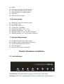
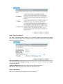
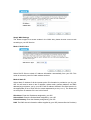
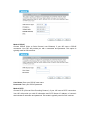
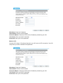
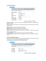
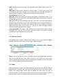
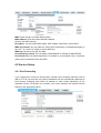
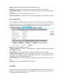
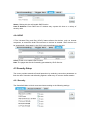
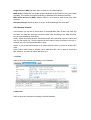
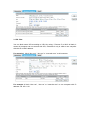
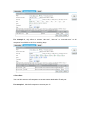
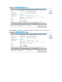
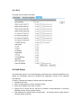
11N 300M Wireless
Router
User Manual
Ver:1.0
Chapter 1 Introduction ................................................................................................................... 3
1.1 Features ............................................................................................................................... 3
1.2 Environments ...................................................................................................................... 4
1.3 System Requirement ........................................................................................................... 4
Chapter 2 Hardware Installation................................................................................................... 4
2.1 Led indicators...................................................................................................................... 4
2.2 Back Panel Features ............................................................................................................ 5
2.3 Typical install ...................................................................................................................... 6
Chapter 3 Quick Install Guide....................................................................................................... 6
3.1 TCP/IP Settings ................................................................................................................... 6
3.2 Getting Started .................................................................................................................... 7
3.3 Setup Wizard ....................................................................................................................... 8
Chapter 4 Advanced Setup ......................................................................................................... 14
4.1 Wireless Advanced setup................................................................................................... 14
4.1.1 WPS...................................................................................................................... 14
4.1.2 Access Control .................................................................................................... 15
4.1.3 Wds....................................................................................................................... 15
4.2 Service Setup..................................................................................................................... 16
4.2.1 Port Forwarding .................................................................................................. 16
4.2.2 Trigger Port .......................................................................................................... 17
4.2.3 DMZ ...................................................................................................................... 17
4.2.4 UPNP.................................................................................................................... 18
4.3 Security Setup ................................................................................................................... 18
4.3.1 Security ................................................................................................................ 18
4.3.2 Access Control .................................................................................................... 19
4.3.3 DoS ....................................................................................................................... 23
4.4 QoS Setup ......................................................................................................................... 23
4.5 Router Setup...................................................................................................................... 24
4.6 System ............................................................................................................................... 25
4.6.1 Upgrade Firmware .............................................................................................. 25
4.6.2 Save/Load Config ............................................................................................... 25
4.6.3 Reboot .................................................................................................................. 25
4.6.4 Password ............................................................................................................. 25
Chapter 1 Introduction
Congratulations on your purchase of this outstanding Wireless Router. The Wireless
Router integrates 4-port switch, firewall, NAT-router and Wireless AP. This product is
specifically designed for Middling and Small Corporation needs. It will allow you to
connect your network wirelessly better than ever, sharing Internet Access, files and fun,
easily and securely. it is easy to configure and operate for even non-technical users.
Instructions for installing and configuring this product can be found in this manual. Before
you install and use this product, please read this manual carefully for full exploiting the
functions of this product.
1.1 Features
z
z
z
z
z
z
z
z
z
z
z
z
z
z
z
z
z
z
z
z
z
z
z
z
z
compatible with the IEEE 802.11b/g and Draft 802.11n wireless technology, WiFi
compliant
802.1x, WEP, WPA TKIP and WPA2 AES/Mixed mode for PSK and TLS (Radius)
Wireless Auto-channel selection
WDS supported with WEP, TKIP and AES encryption
WMM supported
WPS supported
IAPP supported
802.11b/g/n client mode
Wireless ISP supported (set wireless interface on WAN interface)
Support universal repeater mode (one wlan interface used as AP and client
concurrently)
Wireless access control by MAC address (deny or accept)
Control RF module on/off by jumper or scheduling
Support multiple SSID
802.1d with spanning tree protocol
TCP/UDP/ICMP/ARP protocol stack
NAT/NAPT. ALG for: FTP, NetMeeting, SIP, VPN pass-through with multiple sessions
(IPSEC,L2TP, PPTP)
Firewall, IP/MAC/URL key filtering by static or scheduling
Virtual DMZ
DHCP client and server
PPPoE
PPTP client
web server
DNS relay
UPnP IGD
IPSec/VPN gateway and NAT traversal
z
z
z
z
z
z
DDNS
NTP client and daylight saving supported
URL Filtering and DoS (Deny of Service)
QoS supported by IP or MAC address
System log
IGMP proxy and snooping
1.2 Environments
z
z
z
z
z
z
z
z
Dimensions: 202 (L)X120 (W)X31 (H)mm
Unit Weight: 324g
Power Input: 5V DC, 2A
Consumption: 13.5W(Max)
Storage Temperature: -40ºC ~70ºC
Operating Temperature : -10ºC ~50ºC
Storage Humidity: 5% ~95% RH Non-condensing
Operating Humidity: 10% ~90% RH Non-condensing
1.3 System Requirement
z
z
z
z
z
An Ethernet-Based Cable or DSL modem
An 10M or 100M, 10/100M Ethernet Card on PC
TCP/IP network protocol for each PC
RJ45 Twisted-pair
Microsoft IE (or Firefox or Netscape)
Chapter 2 Hardware Installation
2.1 Led indicators
Power(Green): A solid light indicates a porper connection to the power supply.
SYS(Green): The LED is solid light when the router is resetting. And it is flash about two
minutes during WPS working.
WAN(Green):The Link/Act LED serves two purposes. If the LED is continuously
illuminated, the Router is successfully connected to a device through the corresponding
port. If the LED is flickering, the Router is actively sending or receiving data over that port.
WIRELESS (green): The LED is flickering during wireless activity.
LAN 1,2,3,4(green): The Link/Act LED serves two purposes. If the LED is continuously
illuminated, the Router is successfully connected to a device through the corresponding
port. If the LED is flickering, the Router is actively sending or receiving data over that port.
2.2 Back Panel Features
LAN(1,2,3,4): 10/100Mbps RJ45 Auto-sensing . These four LAN ports are where you will
connect networked devices, such as PCs, print servers, remote hard drives, and anything
else you want to put on your network. if you connect this product with the Hub(or
Switchboard ) correctly, the Router’s corresponding LED and the Hub’s(or the
Switchboard’s) must be illuminates.
WAN: 10/100Mbps RJ45 port. The WAN port is where you will connect Cable/DSL Modem
or other LAN.
RESET(WPS): The Reset Button has three functions, WPS, reboot and Factory Default.
When press it less than 2 second, it is WPS function and the Reset LED will flash two
miniute, 2 to 5 second, the router will reboot and greater than 5 second, the router will
restore to factory default.
9V DC, 700Ma: Power inlet.
2.3 Typical install
1. Make sure all devices, including your PCs, modem, and Router, are powered down.
2. Using an Ethernet network cable, connect the LAN or Ethernet network port of the cable
or DSL modem to the Router’s WAN port.
3. Power on the cable or DSL modem, and power on the PC you wish to use to configure
the Router.
4. Connect the included power adapter to the Router. And connect the other end of the
adapter to an electrical outlet.
Chapter 3 Quick Install Guide
3.1 TCP/IP Settings
Before you can access and configure router, you have to setup your network adapter IP
address. According to the following steps to obtain IP address automatically from router
DHCP Server, The following instruction set up the computer running windows operation
system.
Note: The router default IP address is 192.168.1.1.
1. Click Start button and choose Settings, then click Control Panel.
2. Double click Network icon and select Configuration tab in the Network window.
3. Click Add button to add network component into your PC.
4. Double click Protocol to add TCP/IP protocol.
5. Select Microsoft item in the manufactures list. Add choose TCP/IP in the Network
Protocols. Click OK button to return to Network window.
6. The TCP/IP protocol shall be listed in the Network window. Double click TCP/IP to set
the TCP/IP protocol.
7. Select Obtain an IP address automatically in the IP Address tab.
8. Click OK to complete the install procedure and restart your PC to enable the TCP/IP
protocol.
After all is successful, you can check the TCP/IP information via the following command.
Start Æ run Æ cmd and enter command: ipconfig /all.
3.2 Getting Started
To access the configuration pages, open a
web-browser such as Internet Explorer and
enter the IP address of the router
(192.168.1.1).
The Default User/Password: admin
If successful, you can see the status page.
3.3 Setup Wizard
Click on “Wizard” pages, it will guide you to setup your router step by step in simple way.
In this section, there are six steps to do it.
Please follow the steps and complete the router configuration.
Step 1 Setup Operation Mode
The router support three operation mode, Gateway, Bridge and Wireless ISP. And each
mode is suitable for different use, please choose correct mode.
Step 2 Time Zone Settings
The Time Configuration option allows you to configure, update, and maintain the correct
time on the internal system clock. Daylight Saving can also be configured to automatically
adjust the time when needed.
NTP client update: Check this box to connect NTP Server and synchronize internet time.
Automatically Adjust Daylight Saving: Check this box, system will adjust the daylight
saving automatically.
Time Zone Select: Select the Time Zone from the drop-down menu.
NTP Server: Select the NTP Server from the drop-down menu.
Step 3 LAN Settings
Setup the IP address and netmask for the LAN interface.
Step 4 WAN Settings
The Router support five access modes in the WAN side, please choose correct mode
according to your ISP Service.
Mode 1 DHCP Client
Select DHCP Client to obtain IP Address information automatically from your ISP. This
mode is commonly used for Cable modem services.
Mode 2 Static IP
Select Static IP Address if all the Internet port’s IP information is provided to you by your
ISP. You will need to enter in the IP address, subnet mask, gateway address, and DNS
address(es) provided to you by your ISP. Each IP address entered in the fields must be in
the appropriate IP form, which are four octets separated by a dot (x.x.x.x). The Router will
not accept the IP address if it is not in this format.
IP Address: Enter the IP address assigned by your ISP
Subnet Mask: Enter the Subnet Mask assigned by your ISP.
Default Gateway: Enter the Gateway assigned by your ISP.
DNS: The DNS server information will be supplied by your ISP (Internet Service Provider.)
Mode 3 PPPoE
Choose PPPoE (Point to Point Protocol over Ethernet) if your ISP uses a PPPoE
connection. Your ISP will provide you with a username and password. This option is
typically used for DSL services.
User Name: Enter your PPPoE user name.
Password: Enter your PPPoE password.
Mode 4 PPTP
Choose PPTP (Point-to-Point-Tunneling Protocol ) if your ISP uses a PPTP connection.
Your ISP will provide you with IP information and PPTP Server IP Address, of course it
also includes a username and password. This mode is typically used for DSL services.
IP Address: Enter the IP address.
Subnet Mask: Enter the subnet Mask.
Server IP Address: Enter the PPTP Server IP address provided by your ISP.
User Name: Enter your PPTP username.
Password: Enter your PPTP password.
Mode 4 L2TP
Choose L2TP (Layer 2 Tunneling Protocol) if your ISP uses a L2TP connection. Your ISP
will provide you with a username and password.
IP Address: Enter the IP address.
Subnet Mask: Enter the subnet Mask.
Server IP Address: Enter the PPTP Server IP address provided by your ISP.
User Name: Enter your PPTP username.
Password: Enter your PPTP password.
Step 5 WLAN Settings
Wireless Interface: If you do not want to use wireless, uncheck the box to disable all the
wireless functions.
Band: Support 802.11B, 802.11G, 802.11N and mixed. Please choose its band according
to your clients.
Mode: Support AP, Client, WDS and AP+WDS mode.
Network TYPE: This type is only valid in client mode.
SSID: Service Set Identifier, it identifies your wireless nework.
Channel width: Select 40MHz if you use 802.11n or 802.11n mixed mode, otherwise
20MHz, it is default value.
ControlSideband: it is only valid when you choose channel width 40MHz.
Channel Number: Indicates the channel setting for the router. By default the channel is
set to 6.
Step 5 WLAN Security Settings
Secure your wireless network by turning on the WPA or WEP security feature on the router.
This section you can set WEP and WPA-PSK security mode.
The following picture shows how to set the WEP security.
Key length: WEP supports 64-bit or 128-bit security key.
Key Format: User can enter key in ASCII or Hex format.
Key Setting: Enter the key, its format is limited by the Key format, ASCII or Hex.
The following picture shows how to set WPA-PSK security, you can select WPA(TKIP),
WPA2(AES) and Mixed mode.
Pre-Shared Key Format: Specify the format of the key, passphrase or hex.
Pre-Shared Key: Enter the key here, its format is limited by the key format.
Chapter 4 Advanced Setup
4.1 Wireless Advanced setup
4.1.1 WPS
WPS is designed to ease set up of security Wi-Fi networks and subsequently network
managenment. This router supports WPS features for AP mode, AP+WDS mode,
Infrastructure-Client mode, and the wireless root interface of Universal Repeater mode.
WPS: Checking this box and clicking “OK” will disable WPS function. WPS is tured on by
default.
WPS Status: When Router’s settings are factory default, it is set to open securty and
un-configured state, some registers such as Vista WCN can config AP. Otherwise If it
already shows “Configured”, it means that the router has setup its security.
Self-PIN Number: Its is AP’s PIN.
Start PBC: Clicking this button will invoke the Pus Button Configuration of WPS. If one
station wants to connect to the AP, it must click its PBC button in two minute. You can see
the reset led flash this time.
Note: This router also has a hardware button, it is same button with reset. When click this
button less than two second, the AP will run PBC function and the reset LED flashs two
minute, during this time, the station can connect to the AP by its software or hardware
WPS button. By the way, click this button 2 to 5 second, the router will reboot, exceed 5
second, the router will restore factory default.
Client PIN Number: The length of PIN is limited to four or eight numeric digits. If the AP
and Station input the same PIN and click “Start PIN” button in two minutes, they will
establish connection and setup their security key.
4.1.2 Access Control
The Wireless MAC Address Filtering feature allows you to control wireless stations
accessing the router, which depend on the station’s MAC addresses.
Mode: If you choose 'Allowed Listed', only those clients whose wireless MAC addresses
are in the access control list will be able to connect to your Access Point. When 'Deny
Listed' is selected, these wireless clients on the list will not be able to connect the Access
Point. The MAC Address format is 001122334455.
4.1.3 Wds
Wireless Distribution System uses wireless media to communicate with other APs, like the
Ethernet does. To do this, firstly you must set AP Mode to WDS or AP+WDS in basic
setting, then enable WDS function and set another AP MAC which you wan to
communicate with. The WDS supports WEP and PSK security mode. Of course in order to
make APs work, you have to keep them the same channel and security mode.
WDS: Check this box to enable WDS function.
MAC Address: Enter the remote AP MAC address.
Security: Set WDS security.
Encryption: You may select WEP 64bits, WEP 128bits, WPA (TKIP), WPA (AES).
WEP Key Format: You may select to select ASCII Characters or Hexadecimal Digits (in
the "A-F", "a-f" and "0-9" range) to be the WEP Key.
WEP Key: Set key to encrypt your data
Pre-Shared Key Format: You can select PASSPHRASE or HEX(64 CHARACTERS).
Pre-Shared Key: Pre-shared key(PSK) is a method to set encryption keys. Commonly
used in Wi-Fi Protected Access and WEP.
4.2 Service Setup
4.2.1 Port Forwarding
If you configure the router as Virtual Server, remote users accessing services such as
Web or FTP at your local site via public IP addresses can be automatically redirected to
local servers configured with private IP address. In other words, depending on the
requested service (TCP/UDP port number), the router redirects the external service
request to the appropriate server.
Status: Clicking this box will enable Port Forwarding function.
IP Address: That external User accesses the router will redirect to this local IP.
Protocol&Port Range: The packet with this protocol and port will be redirected to ther
local IP.
Comment: You can add some comment for this item.
Current Filter Table: The table shows all you have configured. You can delete one or all.
4.2.2 Trigger Port
Some applications require multiple connections, like Internet games, video conferencing,
Internet calling and so on. These applications cannot work with a pure NAT router. Port
Triggering is used for some of these applications that can work with an NAT router.
Status: Check on to enable this function.
Trigger Port Range: The port for outgoing traffic. An outgoing connection using this port
will “”Trigger” this rule.
Trigger Protocol: The protocol used for Trigger Ports, either TCP, UDP or Both.
Incoming Port Range: CThe port or port range used by the remote system when it
responds to the outgoing request. A response using one of the these ports will be
forwarded to the PC that triggered this rule. .
Incoming Protocol: The Protocol used for Incoming Ports Ranges, either TCP or UDP, or
both.
Comment: You can add some comment for this item.
4.2.3 DMZ
If you have a client PC that cannot run Internet application properly from behind the NAT
firewall or after confniguring the Port Forwarding, then you can open the client up to
unrestricted two-way Internet access.
Status: Clicking this box will enable DMZ function.
Host IP Address: Enter DMZ host IP Address may expose this host to a variety of
security risks.
4.2.4 UPNP
If The Universal Plug and Play (UPnP) feature allows the devices, such as Internet
computers, to access the local host resources or devices as needed. UPnP devices can
be automatically discovered by the UPnP service application on the LAN.
UPnP: Check on to enable UPnP function
Note: The pages also list the forwarding port added by UPnP Service.
4.3 Security Setup
The router provides extensive firewall protection by restricting connection parameters to
limit the risk of intrusion and defending against a wide array of common hacker attacks.
4.3.1 Security
The firewall will allow or block some services according to the following settings.
Ping Access on WAN: Whether allow or block to Ping WAN interface.
IGMP Proxy: IGMPproxy is a simple dynamic Multicast Routing Daemon using only IGMP
signalling. It's intended for simple forwarding of Multicast traffic between networks.
Web Server Access on WAN: Whether allow or not to access Web Server from WAN
interface.
VPN pass through: Whether allow or not the VPN Passthought the router NAT.
4.3.2 Access Control
In this section you can set up some rules, for example MAC filter, IP filter, URL filter and
Port filter. You also can add extra control on these rules according to the date and time,
but you must enable ntp client firstly.
Note 1: When one packet arrives, firewall will search this rules table from up to down and
stop if it find match one. Then the packet will be forward or drop according to the rule. If
unmatch any one, the firmwall will allow it pass.
Note 2: If you set the date and time to do a more precise control, you have to enable NTP
client.
Note 3: Click “Add” button to add this rule to table and click “OK” to apply to router and
take effective. You also can edit or del some one
1. IP Filter
Allow or block the computers according to its IP address.
2. MAC filter
Allow or block the computers according to its MAC address.
3. URL filter
You can block some URL according to URL Key string. If Source IP or MAC is blank, it
means all computer can not access this URL, otherwise it only is valid to one computer
with this IP or MAC address.
For example 1, block “abc.com”, “abc.net” or “www.abc.com” to all computer.
For example 2, block “abc.com”, “abc.net” or “www.abc.com” to one computer with IP
address 192.168.1.101.
For example 3, only allow to access “abc.com”, “abc.net” or “www.abc.com” to all
computer from 09:00 to 18:00 on working days.
4. Port filter
You can limit some or all computers to access some destination IP and port.
For example 1, block all computer to access port 21.
For example 2, block one computer with IP address 192.168.1.101 to access port 21.
4.3.3 DoS
This page used to Block DoS attack.
4.4 QoS Setup
The QoS helps improve your network gaming performance by prioritizing applications. By
default the bandwidth control are disabled and application priority is not classified
automatically.
In order to complete this settings, Please follow the steps below.
1. Enable this function.
2. Enter the total speed or choose automatic mode.
3. Enter the IP address user want to control.
4. specify how to control this PC with this IP address, include Maximum or minimum
bandwith, priority and its up/down speed.
5. Click Add button to add this item to control table, and system does not take effective
utill user applys OK button.
4.5 Router Setup
A static route is a pre-determined pathway that network information must travel to reach a
specific host or network.
Static Route: Click this box to enable static route.
IP Address: The network or host IP address desired to access.
Subnet Mask: The subnet mask of destination IP.
Default Gateway: The gateway is the router or host’s IP address to which packet was
sent. It must be the same network segment with the WAN or LAN port.
Routing Table: Clicking this button will show you all the routing table of the system.
Static Routing table: It only shows the static routing table and you can delete one or all.
4.6 System
4.6.1 Upgrade Firmware
You can upgrade latest Firmware in this page.
4.6.2 Save/Load Config
You can backup or restore the system configuration in this page.
Save to File: Get the router’s settings and store it in your local computer.
Load from File: Restore the settings from the file you backup before from your local
computer, the router will go to the former settings.
Resotore factory: Restore the system settings to factory default.
4.6.3 Reboot
You can reboot device via clicking the Reboot button.
4.6.4 Password
To ensure the Router’s security, you will be asked for your password when you access the
Router’s Web-based Utility. The default user name and password is black.
This page will allow you to add or modify the User name and passwords.