1
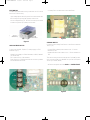
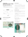
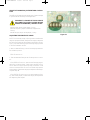
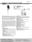
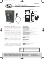
FL-1-BFM:TEMPLATE
12/4/08
10:59 AM
Page 1
Bulletin FL-1-BFM
Series BFM Bulk Flow Monitor
Specifications - Installation and Operating Instructions
4x 3/4˝ CONDUIT KNOCKOUTS
PRODUCT LABEL
FOR MAIN CONTROLLER UNIT
5-9/64 [130.45]
3[76.20]
TRANSFORMER
1-19/32
[40.64]
1A FUSE
RED LED
RELAY
6X 1/2˝ CONDUIT
KNOCKOUT
GREEN
LED
7
[177.80]
1/2
[12.69]
3
SENSOR
[76.20]
TIP
1-1/2
[38.10]
3/32
[2.29]
6´ 18 AWG
WIRE
FLOW SENSOR
SENSITIVITY ADJUSTMENT
POTENTIOMETER
BFM FLOW MONITOR
BFM
BFS
Series BFM Bulk Flow Monitor provides effective
monitoring for most flow/no flow conditions in pipes and
chutes. It’s sensing techniques, which use a Piezo element,
makes the BFM versatile for most flow/no flow applications.
The BFM Control offers many unique advance features
that exceed the industry standards. The BFM Central
Processing Unit monitors movement of almost anything
through a pipe or chute system. The BFM is ideal for
sensing the presence or absence of materials in Pneumatic
Conveying Systems. The BFM offers adjustable sensitivity
depending on the application demand. Also, it provides
easy installation and requires no maintenance. The unit has
L.E.D indicators – flow (green)/ no flow (red).
The BFS-1 Sensor yields many advance features. It
externally mounts to the outside of the pipe or chute. It
provides mounting tabs for easy installation. The Sensor is
prewired with 3´ wire.
Series BFM has many practical applications. You can use it
to monitor Oil Spray Systems, Discharge Chutes,
Distributors, Screw Conveyors, Drag Conveyors, Water
Systems, Air Systems, Pneumatic Systems, Gravity Feed
Systems, Slurry Systems, Chemical Processing, Food
Processing and Rotary Drums.
Part Number
BFM-1
BFM-2
BFM-3
BFS-1
DWYER INSTRUMENTS, INC.
P.O. BOX 373 • MICHIGAN CITY, INDIANA 46361, U.S.A.
SPECIFICATIONS
BFM Specifications
Service: Solids and liquids.
Power Requirement: 120VAC, 220VAC or 12VDC.
Power Consumption: .1A.
Temperature Limits: 120°F (48.9°C).
Output: Relay: SPDT rated 4A @ 125/250VAC, 1/10 HP
@ 125/250VAC, 3A @ 30VDC. TTL: 0-5 V.
Serial Communications: RS-232.
Electrical Connection: Screw Terminal.
Conduit Connection: Knockouts (two 3/4˝ for power,
three 1/2˝ for sensor and outputs).
Enclosure Rating: NEMA 4.
Material: Polycarbonate.
Weight: 3 lbs (1.36 kg).
BFS Specifications
Pipe Size: 1/2˝ to 60˝ (1.27 to 152.4 cm).
Enclosure Rating: NEMA 4.
Electrical Connection: 3´ (0.9 m) of 18 gauge wire.
Temperature Limits: 155°F (68.3°C).
Materials: PVC Type 1 Grade 1 Grey.
Weight: 5 oz (141.8 g).
Descriptions
Control Unit: NEMA 4X, Polycarbonate Housing, Weatherproof, 120VAC
Control Unit: NEMA 4X, Polycarbonate Housing, Weatherproof, 220VAC
Control Unit: NEMA 4X, Polycarbonate Housing, Weatherproof, 12VDC
Sensor
Phone: 219/879-8000
Fax: 219/872-9057
www.dwyer-inst.com
e-mail: [email protected]
FL-1-BFM:TEMPLATE
12/4/08
10:59 AM
Page 2
BFM WIRING
The BFM polycarbonate housing comes with 10 PG conduit
knockouts in the housing.
• A 1-Amp fuse is located next to the transformer.
• High voltage inputs above 24 volt AC should be routed into
the housing through the 3/4˝ (20mm) conduit hole.
• All Low voltage wiring (TTL, RS232, and sensor) should be
routed through the 1/2˝ (14mm) conduit hole.
3/4˝ HIGH
VOLTAGE INPUT
1/2˝ LOW
VOLTAGE INPUT
Figure 3
Figure 1
HIGH VOLTAGE INPUTS
Connect the 120VAC, 50/60 HZ, 1 Amp supply on TB2
terminals (Fig. 2):
• 120VAC (Hot) supply to 117VAC terminal (or 12VDC, 240VAC
per the model)
• AC Common to AC COM terminal
• Earth-Ground to E GND terminal. Must connect to prevent
accidental electrical shock.
SENSOR INPUTS
Connect the low voltage Flow Sensor to the Sensor terminals
TB1 (Fig. 4):
• Positive RED (or White) sensor lead to the “+” Sensor
terminal on TB1.
• Negative BLACK sensor lead to the “-” Sensor terminal on
TB1.
The sensor wiring should be a minimum of 18 AWG stranded 2-conductor cable. Use 18 AWG for up to 500´ (155m) and
16 GA up to 2000' (620m).
• All Sensor wire splices must be SOLID and WATER TIGHT.
Figure 2
Figure 4
FL-1-BFM:TEMPLATE
12/4/08
10:59 AM
Page 3
RELAY AND LOW LEVEL LOGIC WIRING
SIDE VIEW
FRONT VIEW
See those sections later in this manual.
BFM
SENSOR
SENSOR INSTALLATION
The BFS-1 sensor is in very a rugged polymer housing with a
sealed 6´ cable pigtail (Fig. 5):
• Red/Black = Positive
• White/Black = Negative (this is electrically connected to the
metal sensor stud)
NOTE: PILOT HOLES
ARE DRILLED INTO
FLAT SURFACE AND
MOUNTED WITH
PORPER HARDWARE.
BFM
SENSOR
Figure 6
MOUNTING TO A ROUND OR NON-FLAT SURFACE:
(FIG. 7)
BFM SENSOR
• Using strapping (such as heavy duty wire-ties) or clamps to
secure the sensor housing to the pipe so the metal sensing
stud makes firm contact with the surface.
BLACK LEAD
RED/WHITE LEAD
SIDE VIEW
FRONT VIEW
Figure 5
MOUNTING PROCEDURES FOR SENSOR:
The BFS-1 Sensor can be screwed, clamped or strapped in
place and is able to detect flow through most sheet metal.
• Clean the surface area where the sensor is to be installed.
The surface should not have any buildup or scale but does
be perfectly clean.
• The sensor stud located at the bottom of the sensor
housing must make solid contact with the surface of the
pipe to be monitored.
MOUNTING TO A FLAT SURFACE:
Refer to the mounting holes located at each end of sensor
housing (Fig. 6).
• Mark mounting holes.
• Drill pilot holes for mounting screws.
• Screw sensor housing to flat surface.
BFM
SENSOR
NOTE: STRAPS
OR CLAMPS
ARE USED FOR
MOUNTING TO
NON-FLAT
SURFACE
Figure 7
BFM
SENSOR
FL-1-BFM:TEMPLATE
12/4/08
10:59 AM
Page 4
SENSOR LOCATION:
TO ENHANCE SENSITIVY INSTALL THE SENSOR
WHERE THE FLOW IS MOST TURBULENT OR WHERE
MATERIAL IMPACTS THE PIPE WALL.
THE FOLLOWING POINTS ARE IDEAL (FIG 8):
• Pipe elbow
• Point where material drops into spouting or chutes
• Point where material drops from conveyor onto the chute
BE SURE SENSOR STUD
IS MAKING A GOOD
TIGHT CONTACT WITH
MOUNTING SURFACE.
TTL LOGIC OUTPUT:
The TTL Logic output is a 5VDC output.
To obtain a TTL Logic Output install jumper J3 as indicated
on the BFM PCB. Connect logic level output wiring to the
“Out” (+5V) terminal and the Sensor “-” (0V) terminals on TB1.
• NO FLOW: Red LED lights and 0VDC will be present at the
“OUT” terminal.
• FLOW: Green LED will light and 5VDC will be present at the
“OUT” terminal.
RS232 LOGIC OUTPUT:
STUD SENSOR
The RS232 output is an industry standard 5VDC minimum
into 3K load. To obtain an RS232 logical output do not install
jumper J3 as indicated on BFM PCB.
• NO FLOW: Red LED lights and 0 VDC will be present at the
"OUT" terminal.
• FLOW: Green LED will light and 5VDC min. will be present
at the "OUT" terminal.
INPUT
PUMP
Figure 8
NOTE: For proper logic input to your computer, consult your
computer manual for the correct pin configuration for RS232
or TTL.
LOW LEVEL (LOGIC) OUTPUT WIRING
Low level outputs available (Fig. 9):
• TTL logic output
• RS232 logic output
RELAY OUTPUT WIRING
Relay (CTR1) Contact Specifications:
• 4 amp at 125 or 250 VAC
• 1/10 HP at 125 or 250 VAC
• 3 amp at 30 VDC
Relay Output Wiring on TB2 (Fig. 10):
• COM = Common contact
• N/C = Normally closed
• N/O = Normally open
Figure 9
Figure 10
FL-1-BFM:TEMPLATE
12/4/08
10:59 AM
Page 5
SOUNDING AN ALARM TO INDICATE DECREASED
FLOW:
Before the “controlled” equipment can be started again, the
following must occur:
An alarm will sound when flow drops below the preset amount
(Fig. 11):
• Material is flowing past the BFS-1 sensor.
• The Green L.E.D. (FLOW) indicator light is lit indicating
material flow.
• You may have to hold down the Start button until flow
reaches the preset rate.
• When flow drops the relay contacts close to energize the
alarm.
• The power to the alarm (connected to the COM terminal) is
from the motor starter circuit so the alarm can only sound
when the motor is running. When the motor Stop button is
pressed the alarm will silence.
As long as material continues to flow past the BFS-1 sensor
above the preset rate, the machine equipment supplying material will continue to run. If the rate of material flow falls below
the preset level, the relay will open and the machine equipment supplying the material will stop.
START
SWITCH
MACHING
SUPPLYING
MATERIAL
MOTOR
STARTER
STOP
TB2
START
STARTER
COIL
COM
N/0
NOTE: AUXILLARY SET OF
NORMALLY CLUSED
CONCACTS (CLOSED WHEN
STARTER IS ENERGIZED).
117VAC
ALARM
TB2
N/C
COM
AC COM
N/0
M/C
Figure 11
SHUTTING DOWN
DECREASES:
EQUIPMENT
STARTER CIRCUIT WITH BFM SHUTDOWN
WHEN
FLOW
Figure 13
Equipment shut down mode is required if the flow rate drops
below the preset level. The relay is often wired to stop the
equipment that is supplying the material (Fig. 12 and 13).
STOP
START
STARTER
COIL
NORMAL STARTER CIRCUIT
Figure 12
FL-1-BFM:TEMPLATE
12/4/08
10:59 AM
Page 6
SENSITIVITY RANGE ADJUSTMENT AND CALIBRATION
The BFM has (3) three sensitivity range inputs. Select the range
to get the desired sensitivity for the application.
WARNING: TO AVOID ELECTRICAL SHOCK
DISCONNECT AC SUPPLY VOLTAGE BEFORE
ADDING OR REMOVING JUMPERS ON TB1.
• Minimum (low) range: Install jumper J2 (only)
• Medium range: No jumpers installed (as shipped from
factory)
• Maximum (high) range: Install jumper J1 (only)
ADJUSTING THE SENSITIVITY RANGE:
NOTE: The sensitivity range is factory preset to the Medium
range (no jumpers installed). Verify that the supply voltage and
the flow sensor are wired and installed correctly prior to testing (Fig. 14). After selecting proper sensitivity range, proceed
to the next calibration section.
1. With no material flowing, turn the Sensitivity adjustment to
full clockwise position:
• RED LED will turn on.
2. Start the material flowing at the full rate you wish to monitor:
• If the GREEN LED turns on, then turn the Sensitivity adjustment fully counterclockwise. If that causes the RED LED to
turn on then the correct sensitivity range is selected. If that
does not cause the RED LED to turn on (Green stays lit) then
install jumper J2 (Minimum range) and repeat the test beginning with step #1.
• If the GREEN LED does not turn on when material is flowing, then install jumper J2 (Maximum range) and repeat the
test beginning with step #1.
Figure 14
FL-1-BFM:TEMPLATE
12/4/08
10:59 AM
Page 7
BFM CALIBRATION:
Perform sensitivity range jumper selection before performing
calibration.
1. Stop all material from flowing.
2. Turn the Sensitivity adjustment fully clockwise.
3. Start material flowing at the minimum full flow rate desired
• GREEN L.E.D. will light to indicate FLOW.
4. Turn the Sensitivity adjustment counter clockwise until the
RED LED lights to indicate NO FLOW.
5. Turn the Sensitivity adjustment clockwise very slowly until
GREEN LED lights to indicate FLOW.
6. Calibration is now complete.
FINAL SYSTEM CHECK:
• Stop or reduce flow of material and the GREEN LED (FLOW)
will go out and the RED LED (NO FLOW) will light.
MAINTENANCE
Upon final installation of the Series BFM Bulk Flow Monitor,
no routine maintenance is required. A periodic check of
system calibration is recommended. The Series BFM is not
field serviceable and should be returned if repair is needed
(field repair should not be attempted and may void
warranty). Be sure to include a brief description of the
problem plus any relevant application notes. Contact
customer service to receive a return goods authorization
number before shipping.
FL-1-BFM:TEMPLATE
12/4/08
10:59 AM
Page 8
©Copyright 2008 Dwyer Instruments, Inc.
Printed in U.S.A. 12/08
DWYER INSTRUMENTS, INC.
P.O. BOX 373 • MICHIGAN CITY, INDIANA 46361, U.S.A.
Phone: 219/879-8000
Fax: 219/872-9057
FR#R2-443673-00
www.dwyer-inst.com
e-mail: [email protected]