1
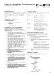
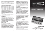
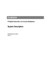
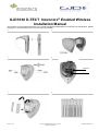
GJD1030 D-TECT Inovonics® Enabled Wireless
Installation Manual
The D-TECT Inovonics MUST be learnt to the control panel/receiver BEFORE it is mounted in its final location. Please
see page 4 of this manual and the Inovonics manual for details.
1
2
3
4
1.Batteries
5
Page 1 of 4
6
© 2013 GJD Manufacturing Limited.
All rights reserved.
October 2013 Rev 1
7
8
9
10
2
1
Page 2 of 4
October 2013 Rev 1
Packaging
Note: The Inovonics transmitter is supplied with the ES link
disabled. If this is required then the transmitter module will
need to be removed to enable the link then replaced.
The package contains:
Ensure the detector's field of view is unobstructed.
•
•
•
•
•
•
•
•
1x wireless detector
3x wall plug & screw sets
2x additional curtain shutters
1x tamper cup
2x tamper caps (different lengths)
1x plastic opening tool
1x installation manual
1x drilling template for fixing holes
Mounting the detector:
1.
A hole-drilling template is provided.
Notes
GJD’s Inovonics® enabled D-TECT®
The wireless detector uses a quad pyro where both sensors
must trigger to cause the detector to signal an alarm ensuring
precise and reliable presence detection.
Programmable options include a variable pulse count and a
choice of detection ranges up to 30 meters.
•
Use the tamper cup on uneven surfaces.
•
Optimum height for the detector is 3m. Higher
mounting heights will result in reduced detection
range.
2.
Remove the cover assembly using the plastic opening tool
and by loosening the locking screw. See Figure 2.
3.
Screw the unit to the wall. Ensure the tamper pin is
correctly located and the tamper switch is closed.
The dual-axis tilt sensor allows 180° of pan and 90° of tilt. This
increases the speed of the outdoor installation and provides
accurate aiming of the detection pattern.
Precision electronics, digital white light filtering, and double
shielding eliminates false alarms from the sun.
Drill the wall to accept the fixing screws and the tamper
cup (if used). See Figures 1 and 3.
Two different length tamper feet are provided for uneven
surfaces. The tamper foot is a push-fit see Figure 1.
4.
The detector housing has a professional appearance with the
sensing module hidden behind the front cover.
Quick installation
When the detector is aligned, powered and programmed:
a.
Fit the cover.
b.
Loosely tighten the locking screw.
c.
Push the two side plastic latches into the base.
d.
Tighten the locking screw.
1. Place two CR123 batteries into the detector battery
holders. Observe the polarity. See figure 4, item 1. The
detection LED will flash 3 times.
Batteries
2. Enter the learning menu on the control panel/receiver. To
learn the device follow the instruction given in the Inovonics
documentation.
Observe correct polarity when fitting.
3. Press and release the programming button once to learn
the device. ( Fig 10, item 2).This action also activates walk test
mode. Note: The learn process may take up to 10 seconds
from pressing the programming button. Learn will be
confirmed on the control panel/receiver.
•
•
•
•
•
•
4. The detector will take approximately 3 minutes to settle.
The detection LED is now enabled for five minutes.
5.
Mount the detector following the instructions below.
The default settings are:
•
•
Range: 30 meters
Pulse count: 1
Fitting the detector
Protect the electronics against water. Trapped moisture can
affect or damage the unit.
Mounting holes should be sealed from within the detector using
acrylic (non-silicone based) sealants. Silicone sealants must
not be used as vapours may corrode the electronics and
metal parts.
Only use CR123 3 V Lithium batteries.
Battery safety information
Do not put in a fire
Do not charge
Do not heat
Do not short circuit
Do not disassemble
Only fit batteries of the same type and voltage
To preserve battery life the detector has a 2-miniute sleep
timer after detection. This is reduced to 8 seconds during walk
test. See also “Walk test” section on page 4.
Beam alignment and masking
The multifunction lens fitted to the GJD1030 detector focuses
seven long-range and seven medium to short-range curtain
beams. The circuitry detects changes in heat and movement in
the beam pattern. The presence of trees, shrubs, ponds, boiler
flues, black tarmac and animals should be considered when
positioning the detector.
PIR sensors are more sensitive to movement across the
beams and less sensitive to movement directly towards or
away.
The detector is fitted with two sliding shutters to reduce the
detection angle.
3/4
October 2013 Rev 1
The shutters are clipped to the pan and tilt module as shown in
Figure 5. Each vertical section of the Fresnel lens gives a
coverage pattern of approximately 10 degrees.
An additional set of shutters is provided for further adjustment.
Figures 7, 8 and 9 show typical beam patterns. A pet alley can
be created my applying the lens mask as shown in Figure 9.
Programming
Figure 10 shows the position of the programming button (2)
and the programming LED (1).
Table 1: Programming settings
Option
1
2
3
1.
Range (m)
10
20
30*
2.
Pulse count
1*
2
•
Default settings
Walk test mode ends automatically five minutes after the last
detection.
Do not conduct walk tests with the cover removed.
The range of the detector increases without the protective front
cover. Therefore the front cover must be fitted to establish the
correct beam pattern. Adjust the range as necessary. Pan and
tilt the detector module over the field of view to obtain the
correct coverage.
Specifications
Detection range
Programmable: 10, 20 or 30m
Coverage
10 to 70° detection angle, 30 x 25m
coverage max.
Adjustment
180° pan, 90° tilt
Fresnel lens
28 zones for each detection element, which
can be masked with the curtain sliders
Optics
Double silicon shielded quad element
eliminates 50,000 Lux of white light
LED
Red alarm
Batteries
2x 3 V CR123
Pulse count is the number of detections before signalling an
alarm. Pulse count 1 is most sensitive.
Current
30 µA
Pulse count
1 or 2
Changing settings:
Control
Digital micro. with non-volatile memory
Walk test
Output test mode with LED indication
Operating temperature
−25 to +65°C
Housing
High impact ABS plastic with HDPE cover,
UV stabilised
Dimensions W x H x D
145 x 145 x 120mm
Weight
268g Net, 425g Gross
Mounting height
Variable up to 6m
Optimum height 3m
1.
Press the programming button once for range and twice
for pulse count.
2.
Wait until the programming LED turns off (typically
4 seconds).
3.
Count the number of times the LED flashes to determine
the current value for that option.
4.
Press the programming button to select the value number
for the new setting. E.g. to change the range to 20m,
press twice.
The LED blinks twice to indicate that the new value was set.
Programme settings are stored in non-volatile memory.
Compliance
Manufacturer
Resets
GJD Manufacturing Limited, Unit 2, Birch Business
Park, Whittle Lane, Heywood, Lancashire, OL10
2SX, UK
1.
Remove the batteries.
Certification
2.
Press and hold the programming button (See Figure 10,
item 2).
R&TTE
3.
Refit the batteries.
This device is in compliance with the essential
requirements and other relevant provisions of
Directive 1999/5/EC.
4.
After the programming LED has flashed, release the
programming button.
Environmental
class
IP65
Learning to control panels/receivers
When the control panel/receiver is in learn mode press the
detector programme button once. After about 10 seconds the
wireless detector will be learnt on to the control panel.
2002/96/EC (WEEE directive): Products marked
with this symbol cannot be disposed of as unsorted
municipal waste in the European Union. For proper
recycling, return this product to your local supplier
upon the purchase of equivalent new equipment, or
dispose of it at designated collection points. For
more information see: www.recyclethis.info.
Walk test
Contact information
In walk test mode, the detection LED option is set to ‘ON’ and
the detection LED will illuminate on detection.
Web: www.gjd.co.uk
To enter the walk test mode, press the programming button
once. The unit can now be aligned.
Page 4 of 4
Tel: +44(0) 1706 363 998
Email: [email protected]
October 2013 Rev 1