1
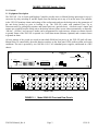
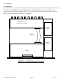
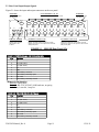
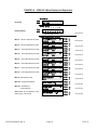
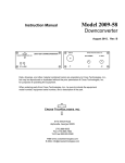
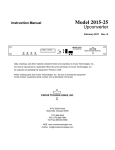
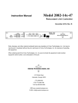
2.3 Front Panel Controls and Indicators
Figure 2.2 shows the front panel controls and indicators.
ALARM LED
Illuminates red
if the switch
malfunctions
ALARM STATUS LEDs
Red LEDs remains on if the
respective unit is alarmed. Red LED
blinks if the respective unit
is not alarmed but the switch
cannot communicate to it via M&C.
Back-Up LEDs
Green LED for BU
indicates
a unit is being
backed up.
S1 - MENU/EXECUTE BUTTON
Press this to get into Program
Mode and to execute any changes.
S2 - VERT. TOGGLE
Vertical toggle switch that controls
values in the Menu items when in
program mode. Does not function in
the normal display mode.
MODEL 2582
SWITCH
CROSS TECHNOLOGIES INC.
SWITCH
UNIT STATUS
1 2 3 4 5 6 7 8 BU
ALARM
PSA
PSB
PROT
MODE
ALARM
OFFLINE
ONLINE
1
POWER LEDs
Green LEDs indicate DC
voltage from each
power supply.
2
3
4
5
6
7
8
BU
ONLINE/OFFLINE LEDs
Green LEDs for CH1 to CH8
indicate they are online. Yellow
LEDs for CH1 to CH8 indicate
they are offline.
FIGURE 2.2
2582-282 Manual_Rev.0
P P P P P P P P 2
A M A A A A A A M
MENU
PROTECTION STATUS
EXECUTE
LCD DISPLAY
Display shows if CH1 to CH8 are protected
or not, what mode CH1to CH8 are in (AUTO,
MANUAL, REMOTE), and which channel is
being backed up (if any).
S3 - HORIZ. TOGGLE
Horizontal toggle switch that
controls which values are being
adjusted. Does not function in the
normal display mode.
2582-282 Front Panel Controls and Indicators
Page 12
12/19/11