1
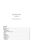
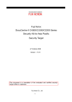
ELECTRONIC SINGLE-PHASE WATT-HOUR METER WITH DIGITAL COMMUNICATION LS1.1 TYPE USER’S MANUAL CONTENTS 1. APPLICATION........................................................................................................................ 5 2. BASIC INFORMATION.......................................................................................................... 5 3. WATT-HOUR-METER SET.................................................................................................... 6 4. WATT-HOUR METER DESIGN.............................................................................................. 6 5. INSTALLATION...................................................................................................................... 7 5.1. External dimensions and fixing way................................................................................ 7 5.2. Connection diagrams....................................................................................................... 9 6. DISPLAYED INFORMATION............................................................................................... 10 6.1. View of LCD display....................................................................................................... 10 6.2. Displayed energy............................................................................................................11 6.3. LED pulse output............................................................................................................11 6.4. Signalling of phase voltage presence.............................................................................11 6.5. Signalling of the active tariff (time zone).........................................................................11 6.6. Signalling of energy counting.........................................................................................11 6.7. Signalling of review, parameter programming or interference with a magnetic field......11 6.8. Signalling of housing opening (interference in the watt-hour meter)............................ 12 6.9. Signalling of extra information....................................................................................... 12 7. CHANGE OF WATT-HOUR METER CONFIGURATION..................................................... 12 7.1. Button............................................................................................................................ 12 7.2. Way of configuration parameter change........................................................................ 13 8. ENERGY MEASUREMENT................................................................................................. 19 8.1. Recording of energy in tariffs......................................................................................... 19 8.2. Recording of total energy.............................................................................................. 19 9. POWER REGISTERS.......................................................................................................... 19 9.1. Averaged maximal power.............................................................................................. 19 9.2. Cumulated power.......................................................................................................... 19 10. END OF THE ACCOUNTING PERIOD.............................................................................. 19 11. AVAILABLE TARIFF GROUPS . ....................................................................................... 20 11.1. Tariff group G11........................................................................................................... 20 11.2. Tariff group G12........................................................................................................... 20 11.3. Tariff group G12w........................................................................................................ 20 11.4. Tariff group G13........................................................................................................... 20 11.5. Tariff group C12a......................................................................................................... 21 11.6. Tariff group C12b......................................................................................................... 21 11.7. Tariff group C12w......................................................................................................... 21 11.8. Tariff group C22a......................................................................................................... 22 11.9. Tariff group C22b......................................................................................................... 22 11.10. List of holidays........................................................................................................... 20 12. OPTICAL INTERFACE...................................................................................................... 22 12.1. Watt-hour meter registers in readout mode................................................................. 23 12.2. Watt-hour meter registers in programming and readout mode.................................... 26 13. RS-485 OR RS-232 SERIAL INTERFACE WITH MODBUS PROTOCOL (OPTION)....... 27 13.1. List of serial interface parameters............................................................................... 27 13.2. Map of watt-hour meter registers................................................................................. 28 14. INTERNAL CONTROL CLOCK (for options with external clock)................................. 32 15. TECHNICAL DATA............................................................................................................ 32 16. VERSION CODES............................................................................................................. 34 17. MAINTENANCE AND WARRANTY.................................................................................. 35 1. APPLICATION LS1.1 electronic watt-hour meters are destined for the direct measurement of active energy in single-phase power networks with the simultaneous display of measured quantities. They can be applied for settlement of accounts with electric power plants, for industrial process control, for settlement of accounts with sub-hirers. These watt-hour meters are designed to be mounted on a wall. The housing enables to set a legalization leaden seal on the watt-hour meter cover and a leaden seal of the energy supplier on the terminal box. Thanks to built-in communication interfaces, they can be applied as an element of energy management systems. These watt-hour meters have a 7-digit LCD display with additional graphic symbols. As standard, there is also a lighting and pulsing red diode (LED) and interface for data transmission in infrared. 2. BASIC INFORMATION LS1.1 electronic watt-hour meters are resistant to a strong external magnetic field, e.g. a neodymium magnet. A special designed antitheft protection has been applied in the mechanical construction, in the electronic system and in the software. Protection of the construction - The frontal cover, having on the whole perimeter, internal and external projections enclosing bilaterally and tightly the base wall, unabling the interference with a tool inside the watt-hour meter. - The cover is fixed to the base by two screws, what gives a durable junction secured additionally by leaden seals. - The shield of the terminal box additionally presses down the cover and protects the fixing screws by leaden seals. - The junction of the cover and the base is sealed, what protects against the infiltration of fluids and dust. Electronic and programmed protection - Sensor of mechanical interference in the watt-hour meter. The lift of the watt-hour meter frontal cover causes the sensor operation, and the existed interference is signalled on the display. Additionally, the date and the interference duration are stored in the watt-hour meter memory. - Sensor of the interaction by a strong magnetic field, e.g. a neodymium magnet. The application of a strong magnetic field to the watt-hour meter causes the sensor operation, and the existed interference is signalled on the display. - The number of mechanical interference and interactions by a magnetic field is durably recorded in the watt-hour meter. Protection against the switching of power network wires The watt-hour meter counts the energy when interchanging network wires. The energy is accounted regardless of the flow direction. The shield of the terminal box can be optionally made of a transparent plastics enabling a visual inspection of the electrical connection correctness with the user (energy receiver). The watt-hour meter equipment with a communication interface or a radio transmitter gives the possibility of a permanent monitoring, data archiving, visualization and report. The LS1.1 watt-hour meter can be included into existing computer networks, what is rendered possible by offered interface and protocol converters produced by LUMEL. 3. WATT-HOUR METER SET The set of the watt-hour meter is composed of: - LS1.1 watt-hour meter 1 pc - User’s manual 1 pc - Warranty card 1 pc 4. WATT-HOUR METER DESIGN The construction of the LS1.1 watt-hour meter is presented on the fig. 1. The watt-hour meter housing is made of an insulated material (lexan) and ensures the service safety in the protection class II. The review and setting of watt-hour meter parameters are realized by the button (4) situated in the shield (8). The button is adapted to be sealed with lead. After sealing the button, there is possible to review selected data on the display. The function of parameter setting is accessible after removing the leaden seal and turning the button. Fig. 1a Watt-hour meter design - view of the watt-hour meter with the fixed terminal box shield (7) 1. Base 2. 7-digit liquid crystal display (LCD) with graphical symbols 3. Upper hanger - metallic element fixing the watt-hour meter to the power box or the watt-hour meter niche 4. Two-function button - review and setting of watt-hour meter parameters 5. Optical link - enables the readout and write of data from and to the watt-hour meter 6. Screw - fixes the shield (7) and is adapted to seal with lead by the power plant 7. Shield of the terminal box 8. Shield of the watt-hour meter - It is fixed to the base by internal catches and two screws (10) 9. LED diode - generates light pulses with a defined time-constant (imp/kWh) Fig. 1b Watt-hour meter design - View of terminals after removing the terminal shield (7) 10. Fixing screws - to fix the shield (8), they are adapted to seal with lead by the producer or to put the verification mark 11. Fixing holes - with the metallic upper hanger (3), they define the fixing points of the watt-hour meter in the power box (cabinet) or the niche for watt-hour meters 12. Terminal box - enables the connection of measuring circuits 13. Interface link - to connect interface wires 5. INSTALLATION 5.1 External dimensions and fixing way Watt-hour meter overall dimensions are presented on the fig. 2. The LS1.1 watt-hour meter is fixed on the wall. Housing dimensions: 206 x 120 x 65 mm. The box has screw terminals with 6.5 mm internal diameter to connect to the power network, and auxiliary circuits with a wire up to 1.5 mm2 cross-section. Fig. 2 Watt-hour meter overall dimensions 5.2 Connection diagrams Single-tariff watt-hour meter for direct connection Watt-hour meter with pulse output Watt-hour meter with an RS-485 communication interface and Modbus protocol Watt-hour meter with an RS-232 communication interface and Modbus protocol Two-tariff watt-hour meter with an external clock Fig.3 External connection diagrams of the watt-hour meter 6. DISPLAYED INFORMATION It is possible to readout following information on the LCD display: ¡Energy in the current zone, ß Current time (in the hour:minute format), ß Current date (in the year.month.day format), ß Energy in zone T1, ß Energy in zone T2 (if occurs in the set tariff group), ß Energy in zone T3 (if occurs in the set tariff group), ß Energy in zone T4 (if occurs in the set tariff group), ß Total energy, ß Closing time of the accounting period (in the hour:minute format), ß Closing date of the accounting period (in the year.month.day format), ß Energy in zone T1 at the end of the previous accounting period, ß Energy in zone T2 at the end of the previous accounting period (if occurs in the set tariff group), ß Energy in zone T3 at the end of the previous accounting period (if occurs in the set tariff group), ß Energy in zone T4 at the end of the previous accounting period (if occurs in the set tariff group), ß Total energy at the end of the previous accounting period, ß Symbol of the set tariff group. The start of information review, i.e. the transition from the energy display mode in the current zone, follows after pressing the button in the SCROLL position. Successive information are sequentially accessible. After 30 seconds since the last button pressure, the watt-hour meter returns to the normal working mode. Depending on the option and watt-hour meter configuration, the number of accessible information in the review mode can be smaller 6.1 VIEW OF THE LCD DISPLAY Fig. 4 LCD display 10 6.2 Displayed energy In the LS1.1 watt-hour meter, the energy is displayed in kWh, with one decimal place. The counter register has 7 digits. 6.3 LED pulse output The red lighting LED diode is the index of the energy flow. The frequency of light flashes is proportional to the current energy flow. 6.4. Signalling of the phase voltage presence Fig. 5 Index of the phase voltage presence The L1 index signals the presence of the phase voltage In case when its value exceeds 0.9 Un 6.5 Signalling of the active time zone (tariffs) Fig. 6 Tariff indexes The active tariff zone is indicated by one of the symbols, e.g. for the first tariff the T1 symbol is displayed. For the total energy, all accessible tariff symbols together with the sum mark are displayed. 6.6 Signalling of energy accounting Fig. 7 Index of energy accounting For signalling the energy accounting, an index composed of 3 arrows is accessible. If the energy is accounted, two arrows are shifting, giving the effect of the index turning round. If the watt-hour meter does not account the energy, all the 3 arrows are visible (they do not turn round). The index turning round speed is constant and does not depend on the measured energy. 6.7 Signalling of review and parameter programming or interference by a magnetic field. Fig. 8 Index of parametr review programming or field interference When the user reviews parameters in the SCROLL mode or enters in the SET programming mode, the symbol presented on the fig.8 is visible on the display. 11 The flickering symbol signals a strong magnetic field interference. If the watt-hour meter is under the influence of this field, then the index is lighting in a permanent way. If the magnetic field duration was longer than 30 seconds and the watt-hour meter is not under its influence, the index flickers till the time of erasing register of interference by the magnetic field through the optical link. 6.8 Signalling of housing opening (interference inside the watt-hour meter) The lift of the frontal cover (interference inside the watt-hour meter) is signalled on the display by the flickering inscription „OPEN” alternatively with the current readout. In the same time, the date and the interference duration are recorded in the watt-hour meter memory. Fig. 9 Screen signalling the housing opening 6.9 Signalling of additional information Fig. 10 Index of additional information The visible signal above on the display signals that the write through the optical link is allowed. However, the flickering symbol signals the incorrect work of the watt-hour meter. 7 CHANGE OF WATT-HOUR METER CONFIGURATION The change of watt-hour meter configuration is possible in the programming mode (SET). The watt-hour meter is switched in the SET mode by means of the button. 7.1 Button The watt-hour meter has one button. By means of this button set on the scroll position in the normal watt-hour meter operation, it is possible to review parameters described in the point 6. In this position, the button can be leaden sealed. To transit to the SET position, one must remove the seal if exists and turn the button of 90° to the right. The table 1 presents the button functions. SCROLL position SET position Fig. 11 Available button positions 12 Button functions Button SCROLL SCROLL SCROLL (> 2 sec.) SET (> 2 sec.) SET SET (> 2 sec.) Table 1 Working mode Function REVIEW PROGRAMMING Review of parameters Selection and change of programmable parameter values PROGRAMMING REVIEW PROGRAMMING PROGRAMMING Automatic incrementation of the parameter value Entry into the parameter configuration mode Selection of the parameter Acceptation of the parameter group change The watt-hour meter transits from the parameter review mode, or from the configuration mode to the normal operation mode after 30 sec. from the last button use. 7.2. Service algorithm The scheme of the main menu of the watt-hour meter configuration is presented on the fig. 10a. After pressing and hold down the button during at least 2 sec., in the SET position, it is possible to program parameters. The transition between parameters is made by means of the button on the SET position. The table 2 comprises the parameter description. The return to the normal operation follows after reviewing of all visible groups of parameters or automatically, after the laps of 30 sec. since the last button pressing. Caution: same parameters or paremeter settings can be invisible (inaccessible) depending on the watt-hour meter version and its current configuration. Fig. 12a Watt-hour work algorithm - Main menu 13 Fig. 12b Algorithm of the watt-hour meter work - menu of the optical interface. Fig. 12c Algorithm of the watt-hour meter work - menu of the real-time clock Fig. 12d Algorithm of the watt-hour meter work - menu of the accounting period closure 14 Fig. 12e Algorithm of the watt-hour meter work - menu of tariffs 15 Fig. 12f Algorithm of the watt-hour meter work - menu of serial interface Fig. 12g Algorithm of the watt-hour meter work - menu of interference by a magnet and cover opening Fig. 12h Algorithm of watt-hour meter work - menu of power averaging 16 List of configuration parameters Main menu opti Parameter symbol set Parameter description Possibility of write through the optical interface tr Selection on the tariff H1 T1 time for tariff groups G12, G12w, C12b, C12w, USEr T2 time for tariff groups G12, G12w, C12b, C12w, USEr H2 H3 H4 ran1 tariff T3 time for tariff groups G12, G12w, C12b, C12w, USEr T4 time for tariff groups G12, G12w, C12b, C12w, USEr Selection of tariff for the time interval since H1 till H2. Parameter accessible only in the USEr tariff group. ran2 Selection of tariff for the time interval since H2 till H3. Parameter accessible only in the USEr tariff group. ran3 Selection of tariff for the time interval since H3 till H4. Parameter accessible only in the USEr tariff group. ran4 Selection of tariff for the time interval since H4 till H1. Parameter accessible only in the USEr tariff group. sat sun Hol Table 2 Range of parametr changes off: disabled on: enabled g11: tariff group G11 g12: tariff group G12 g12u: tariff group C12w C12a: tariff group C12a C12b: tariff group C12b C12u: tariff group C12w g13: tariff group G13 C22a: tariff group C22a C22b: tariff group C22b UsEr: User’s tariff 06:00...07:00 or optionaly for USEr 13:00...4:00 or optionaly for USEr 15:00...6:00 or optionaly for USEr 22:00...23:00 or optionaly for USEr t1: T1 zone t2: T2 zone t3: T3 zone t4: T4 zone t1: T1 zone t2: T2 zone t3: T3 zone t4: T4 zone t1: T1 zone t2: T2 zone t3: T3 zone t4: T4 zone t1: T1 zone t2: T2 zone t3: T3 zone t4: T4 zone Selection of tariff zone for Saturdays. Parameter accessible only for the USEr tariff group. The selection of „Cur” parameter, causes that the watt-hour meter counts the energy according to settings of „rAn1... 4” parameters. Cur: as in the selected tariff group t1: T1 zone t2: T2 zone t3: T3 zone t4: T4 zone Selection of tariff zone for Sundays. Parameter accessible only for the USEr tariff group. The selection of „Cur” parameter, causes that the watt-hour meter counts the energy according to settings of „rAn1... 4” parameters. Cur: as in the selected tariff group t1: T1 zone t2: T2 zone t3: T3 zone t4: T4 zone Selection of tariff zone for Holidays. The selection of „Cur” parameter, causes that the watt-hour meter counts the energy in the zone resulting from the set tariff. Cur: as in the selected tariff group t1: T1 zone t2: T2 zone t3: T3 zone t4: T4 zone 17 List of configuration parameters Main menu clock Parameter symbol dy dn dd th tn atc eob eob Parameter description Current month 01...12 Current day 01...31 Current hour 00...23 00...59 Current minute Automatic change of the winter/summer time off: turned off on: turned on Instant execution of the accounting period closure no: no yes: yes Day of automatic closure of the accounting period 01...28 th Hour of automatic closure of the accounting period 00...23 tn Minute of automatic closure of the accounting period 00...59 adr bd 18 2001...2035 Current year Working mode nodbus pouer Range of parametr changes dd rs Clear Table 2 (continuation) Clr pa a8n1: ASCII 8N1 a7e1: ASCII 7E1 a7o1: ASCII 7O1 r8n2: RTU 8N2 r8e1: RTU 8E1 r8o1: RTU 8O1 r8n1: RTU 8N1 1... 247 Address Baud rate Cancelation of the magnet interference and/or the cover opening Mode of power averaging 4.8: 4800 bit/sec 9.6: 9600 bit/sec 19.2: 19200 bit/sec no: no yes: yes 15.03: 15 min, subrange 3 min 15.05: 15 min, subrange 5 min 15.15: 15 min, subrange 15 min 30.06: 30 min, subrange 6 min 30.10: 30 min, subrange 10 min 30.30: 60 min, subrange 30 min 60.12: 60 min, subrange 12 min 60.20: 60 min, subrange 20 min 60.60: 60 min, subrange 60 min 8 ENERGY MEASUREMENT 8.1 Recording of energy in tariffs In any time, the watt-hour meter accounts the energy in one of the tariffs. When the register reaches its maximal value 999 999.9 kWh, it is automatically reset and the account begins from zero. 8.2 Recording of total energy The recording of the total energy consists in storing the total energy consumption in one register, independently of the tariff. When the register reaches its maximal value 999 999.9 kWh, it is automatically reset and the account begins from zero. 9 POWER REGISTERS 9.1 Averaged maximal power The measurement of maximal power can be performed in 15, 30 or 60 minutes’ periods. The locking mode or the shift mode is accessible to calculate the power. For the shift mode, one can choose 5 or 3 subperiods falling on the integration period. For 15 minutes, there will be 3 or 5 minutes’ segments, for 30 minutes, 6 or 10 minutes’ segments and for 60 minutes, 12 or 20 minutes’ segments. The selected number of subperiods composes the period of power integration. After the first complete shift period including all subperiods, the next subperiod will be accounted and the first is not be taken in consideration. The watt-hour meter stores in its memory the maximal power for the current and the previous accounting period, and the time and date of its occurrence. 9.2 Cumulated power The cumulated power is the power register increased by the averaged value of the maximal power at the end of the accounting period. 10 END OF THE ACCOUNTING PERIOD At the moment of the accounting period closure, values of energy from all time zones and the total energy will be memorized and at the same time, values of the accounted energy do not undergo to changes. The automatic closure can follow automatically, on the defined day of the month and in the given time. The configuration consists on writing the minute, hour and day of the accounting period closure. The closure of the accounting period, the date and time of this operation is written. When there is a lack of closure possibility, e.g. because of a lack of supply, the closure process will be carried out after the supply voltage recovery. After each closure of the accounting period, it is increased by one closure counter. Note: It is recommended to close the accounting period during the watt-hour meter installation, so as to memorize initial values of energy already counted. If the closure has been carried out in the day in which the automatic closure should occur, then the automatic closure will be cancelled on this day. 19 11 AVAILABLE TARIFF GROUPS 11.1 Tariff group G11 The energy is counted during the whole time in the T1 zone. 11.2. Tariff group G12 Zone number 24 hours’ zone 1. Daily zone (T1) 2. Night-time zone (T2) Table 3 Period of time (1 January - 31 December) H1 - H2 H3 - H4 H4 - H1 H2 - H3 Notations: H1: 600 ÷ 700 H2: 1300 ÷ 1400 H3: 1500 ÷ 1600 H4: 2200 ÷ 2300 Holidays are included to the zone depended on the setting of Hol parameter in tAriFF. 11.3. Tariff group G12w Table 4 Zone number 24 hours’ zone Period of time (1 January - 31 December) 1. Daily zone (T1) H1 - H2 H3 - H4 2. Night-time zone (T2) H4 - H1 H2 - H3 Notations: H1: 600 ÷ 700 H2: 1300 ÷ 1400 H3: 1500 ÷ 1600 H4: 2200 ÷ 2300 Holidays are included in the zone depended on the setting of Hol parameter in tAriFF Saturdays and Sundays are included In the 24 hours’ zone to the second zone - night-time zone 11.4. Tariff group C13 Table 5 Period of time Winter Summer (1 October - 31 March) (1 April - 30 September) Zone number 24 hours’ zone 1. Ante-meridian peak (T1) 700 - 1300 700 - 1300 2. Post-meridian peak (T2) 00 19 - 22 1600 - 2100 3. Remaining hours of the 24 hours’ zone (T3) 1300 - 1900 2200 - 700 1300 - 1600 2100 - 700 00 Legal day-offs, Saturdays and Sundays are included in the 24 hours’ zone to the third zone, as remaining hours of the 24 hours’ zone. 20 11.5. Tariff group C12a Table 6 Period of time Zone number 24 hours’ zone 1. 2. Summer (1 April - 30 September) Winter (1 October - 31 March) Peak zone (T1) 800 - 1100 2000 - 2100 800 - 1100 1700 - 2100 Extrapeak zone (T2) 1100 - 2000 2100 - 800 1100 - 1700 2100 - 800 Holidays are includ to the zone depended on the setting of Hol parameter in tAriFF 11.6. Tariff group C12b Table 7 Zone number 24 hours’ zone Period of time (1 January - 31 December) 1. Daily zone (T1) H1 - H2 H3 - H4 2. Night-time zone (T2) H4 - H1 H2 - H3 Notations: H1: 600 ÷ 700 H2: 1300 ÷ 1400 H3: 1500 ÷ 1600 H4: 2200 ÷ 2300 Holidays are included to the zone depended on the setting of Hol parameter in tAriFF 11.7. Tariff group C12w Table 8 Zone number 24 hours’ zone Period of time (1 January - 31 December) 1. Daily zone (T1) H1 - H2 H3 - H4 2. Night-time zone (T2) H4 - H1 H2 - H3 Notations: H1: 600 ÷ 700 H2: 1300 ÷ 1400 H3: 1500 ÷ 1600 H4: 2200 ÷ 2300 Saturdays and Sundays are included In the 24 hours’ zone, to the second zone - night-time Holidays are included to the zone depended on the setting of Hol parameter in tAriFF 21 11.8. Tariff group C22a Zone number 24 hours’ zone 1. Peak zone (T1) 2. Table 9 I, II, XI, XII 800 - 1100 1600 - 2100 00 00 Extrapeak zone (T2) 2100 - 8 00 11 - 16 Period of time III, X IV, IX 800 - 1100 800 - 1100 1800 - 2100 1900 - 2100 2100 - 800 1100 - 1800 2100 - 800 1100 - 1900 V, VI, VII, VIII 800 - 1100 2000 - 2100 2100 - 800 1100 - 2000 Holidays are included to the zone depended on the setting of Hol parameter in tAriFF 11.9. Tariff group C22b Table 10 Zone number 24 hours’ zone Period of time (1 January - 31 December) 1. Peak zone (T1) 600 - 2100 2. Extrapeak zone (T2) 2100 - 600 Holidays are included to the zone depended on the setting of Hol parameter in tAriFF 11.10. Liste of holidays Following days are implemented in the watt-hour meter, as permanent holidays: statutorily free of work: 1st January - New Year, 1st May - International Holiday of the 1st of May, 3rd May - National Holiday of 3rd May, 15th August - Assumption, 1st November - All Saints Day, 11st November - Independence Day, 25th December - First Day of Christmas, 26th December - Second Day of Christmas. Movable feasts: The first day of Easter, Corpus Christi. 12 OPTICAL INTERFACE Parameter set of the optical link of the LS1.1 watt-hour meter: - conformity with the standard EN62056-21 - manufacturer identifier LML - baud rate identifier 4 - watt-hour meter identifier LS11-LUMEL - transmission protocol mode C of transmission - transmission initialization 300 baud - available baud rates 300, 600, 1200, 2400, 4800 baud - character format acc. to ISO 1177 7E1 - write interlock button secured by a leaden seal The optical interface in the watt-hour meter enables the realization of following functions: - data readout from the watt-hour meter, - write of selected parameters to the watt-hour meter, - closure of the accounting period. The write of parameters and closure of the current accounting period are possible after breaking the leaden seal and setting the button on the SET position. 22 To unlock or lock the write, one must: - press the SET button in a time longer than 2 sec, - pressing the SET button, transit to the „opti” menu, - by means of the SCROLL button unlock the „sEt on” write or lock the „sEt off” write, - pressing the SET button in a time longer than 2 sec, accept the change, - pressing the SET button, exit from the SETUP procedure. The locking of the write follows automatically after a 5 minutes’ lack of communication through the optical link. 12.1 Watt-hour meter registers in the readout mode The list of registers with identifiers and the example of contents in case of data readout is presented in the tables below. Note: Depending on the option and watt-hour meter configurations, the number of available registers for readout can be smaller. Table 11 Identifier (ASCII characters) 28 Format of ASCII characters (example of contents) 12:34:56 29 25-11-02 0.0 AbcDeFgHiJ Parameter Current time Current date (dd:mm:yy) User’s identifier 0.0.1 02110001 Factory number 0.8.1 000123.4*kWh Energy in zone 1 0.8.2 000423.4*kWh Energy in zone 2 0.8.3 000623.4*kWh Energy in zone 3 0.8.4 000723.4*kWh Energy in zone 4 Total energy from all zones 0.8.0 001323.4*kWh 0.6.0 10:23 20-11-02; Time and date of the maximal 15’, 30’ or 60’ power occurrence 99.2*kW and its value. 70. 10:23 20-11-02 Time and date of the account period closure. 0.8.1*00 000123.4*kWh Energy in zone 1 at the end of the previous account period. 0.8.2*00 000423.4*kWh Energy in zone 2 at the end of the previous account period. 0.8.3*00 000623.4*kWh Energy in zone 3 at the end of the previous account period. 0.8.4*00 000723.4*kWh Energy in zone 4 at the end of the previous account period 0.8.0*00 001323.4*kWh Total energy at the end of the previous account period. 0.6.0*00 10:23 19-11-02; Time and date of the max. 15’, 30’ or 60’ power occurrence in 90.2*kW the previous account period and its value. 0.6 6344.7*kW 0.1. 22352 Cumulated power (max. „65535”) Counter of account period closures (max. „65535”) 23 Table 11 (continuation) Identifier (ASCII characters) Format of ASCII characters (example of contents) 54. 010301 FF 01101000 00011000 0.43 7 Parameter Watt-hour meter status: 1 st character - Signalling of voltage in the phase (‘0’ - U<0.9 Un; ‘1’ - U0.9 Un) 2 nd character - Always ‘0’ 3 rd character - Always ‘0’ 4 th character - Current time zone: ‘1’ - 1 st zone T1 ‘2’ - 2 nd zone T2 ‘3’ - 3 nd zone T3 ‘4’ - 4 th zone T4 5 th character - Signalling of cover opening (‘0’ or ‘1’) 6 th character - Signalling of magnetic field interference (‘0’ or ‘1’) Register of watt-hour meter errors (see table 12) (‘0’ or ‘1’) Time of power averaging and number of subperiods: ‘0’ - 15 min, 3 min’subperiod ‘1’ - 15 min, 5 min’subperiod ‘2’ - 15 min, 15 min’subperiod ‘3’ - 30 min, 6 min’subperiod ‘4’ - 30 min, 10 min’subperiod ‘5’ - 30 min, 30 min’subperiod ‘6’ - 60 min, 12 min’subperiod ‘7’ - 60 min, 20 min’subperiod ‘8’ - 60 min, 60 min’subperiod 50. 17;13:55 Day and time in which the account period is closed. (day ‘00’ - automatic closure is off; day ‘01’...‘28’; hour ‘00’...‘23’ : minute ‘00’...‘59’) 51. 05 07:20; 10:12; 51.1 22:30; 23:30 Tariff groups: ‘00’ - G11 ‘01’ - G12 ‘02’ - G12w ‘03’ - C12a ‘04’ - C12b ‘05’ - C12w ‘06’ - G13 ‘07’ - C22a ‘08’ - C22b ‘09’ - USEr (user’s tariff) ‘10’ - controlled by the external clock 24 Variable hours for tariffs: G12, G12w, C12b, C12w, USEr 51.2 Table 11 (continuation) 1010114 Time zones for Saturdays, Sundays and holydays (only for USEr tariff) 1st character - zone for hour interval since H1 till H2 2 nd character - zone for the hour interval since H2 till H3 3 rd character - zone for the hour interval since H3 till H4 4 th character - zone for the hour interval since H4 till H1 Meaning of 1...4 charac- ‘0’ - T1 zone ‘1’ - T2 zone ‘2’ - T3 zone ‘3’ - T4 zone 5 th character - Zone for Saturdays (only for USEr tariff) 6 th character - Zone for Sundays (only for USEr tariff) 7 th character - Zone for holidays Meaning of 5...7 characters: ‘0’ - as in the selected tariff group ‘1’ - T1 zone ‘2’ - T2 zone ‘3’ - T3 zone ‘4’ - T4 zone In case when choosing ‘0’, time zones are defined acc. to the chosen tariff group (see the description of tariff zones in Table 2. 52. 22112 Configuration of the serial link (mode, address, baud rate): 1 st character - mode ‘1’ - ASCII 8N1 ‘2’ - ASCII 7E1 ‘3’ - ASCII 7O1 ‘4’ - RTU 8N2 ‘5’ - RTU 8E1 ‘6’ - RTU 8O1 ‘7’ - RTU 8N1 2, 3, 4 th character - address („001”...”247”) 5 th character - baud rate ‘0’ - 4800 baud ‘1’ - 9600 baud ‘2’ - 19200 baud 53. No of the program version 6.4 55. 1 Automatic change of winter time/summer time ‘0’ - off ‘1’ - on 76.1 10:12 25-11-05; Hour and date of the beginning of interference by a strong magnetic field 76.2 0000000327 Duration of interference by a strong magnetic field [sec] 77. 0 Index of cover opening (interference into the watt-hour meter) ‘0’ - There was no opening ‘1’ - There was or/there is an opening 78 00003 Number of register erasing of interference by a strong magnetic field and/or housing opening. 25 Description of the register - watt-hour meter errors Character number 0 1 2 3 4 5 6 7 8 9 10-14 15 Table 12 Description Detection of erroneous contents - energy in zone T1 Detection of erroneous contents - energy in zone T2 Detection of erroneous contents - energy in zone T3 Detection of erroneous contents - energy in zone T4 Detection of erroneous contents - total energy Detection of erroneous contents - energy in zone T1 in the previous account period Detection of erroneous contents - energy in zone T1 in the previous account period Detection of erroneous contents - energy in zone T2 in the previous account period Detection of erroneous contents - energy in zone T3 in the previous account period Detection of erroneous contents - total energy in the previous account period Not used Incorrect value of the error register. 12.2 Watt-hour meter registers in the programming and read-out mode List of watt-hour meter registers with identifiers and example of contents in case of readout and/or data write in the programming mode. Table 13 Identifier (ASCII characters) T A Format of ASCII characters (example of contents) Parameter 12:34:56 Current time and date 25-11-02 1 Automatic time change winter/summer acc. to fig.10c Func tions R/W R/W I AbcDeFgHiJ User’s identifier R/W N 02110001 Factory number R D 7 Power averaging time and number of subperiods: (like in table 11) E 17;13:55 Day and time in which the account period is closed. (day „00”... „28”) R/W Kind of tariff group (like in table 11) R/W Variable hours for tariffs: G12, G12w, C12b, C12w, USEr R/W C 22112 Configuration of the serial link (mode, address, baud rate) (like in table 11) R/W R 1 Register erasing of interference by a strong magnetic field and cover opening. G H 26 05 07:20; 10:12 22:30; 23:30 R/W R/W Table 13 (continuation) Z 1010111 Selection of the time zone for tariff hours, Saturdays, Sundays and holidays (only for USEr tariff). R/W 1 st character – selection of zone for the hour interval since H1 till H2 2 nd character – selection of zone for the hour interval since H2 till H3 3 rd character – selection of zone for the hour interval since H3 till H4 4 th character – selection of zone for the hour interval since H4 till H1 Meaning of 1...4 characters: ‘0’ - T1 zone ‘1’ - T2 zone ‘2’ - T3 zone ‘3’ - T4 zone 5 th character - selection of zone for Saturdays (only for USEr tariff) 6 th character - selection of zone for Sundays (only for USEr tariff) 7 th character - selection of zone for holidays Meaning of 5...7 characters: ‘0’ - as for the selected tariff group ‘1’ - T1 zone ‘2’ - T2 zone ‘3’ - T3 zone ‘4’ - T4 zone In case when ‘0’ is chosen, time zones are defined acc. to the selected tariff group (see the description of the tariff zones in Table 2) Notations: R - only for readout R/W - readout and write Note: In case of a watt-hour meter configuration, when the given parameter is not used, the caractere code ‘–’ (minus) is returned. 13. RS-485 or RS-232 SERIAL INTERFACE WITH MODBUS PROTOCOL 13.1 Set of serial interface parameters: identifier watt-hour meter address baud rate working mode information unit maximal response time 0xA0 1... 247 4800, 9600, 19200 bodów, ASCII, RTU, ASCII: 8N1, 7E1, 7O1; RTU: 8N2, 8E1, 8O1, 8N1, 600 ms. Factory settings: address: 1, baud rate: 9600 baud, RTU mode: 8N2. LS1.1. watt-hour meter realizes following protocol functions: Table 14 Code Meaning 03 Readout of n-registers 17 Identification of the slave device 27 13.2 Map of watt-hour meter registers Data are placed in 16-bit registers. Process variables and watt-hour meter parameters are placed in the register address space in a way depending on the type of the variable value. Bits in the 16-bit registers are numbered from the youngest to the oldest (b0-b15). Table of watt-hour meter 16-bit registers Register Parameter number Description Range 0... 65535 Table 15 4000 word 4001 word 2001... 2035 Current year Watt-hour meter status description in table 16. 4002 word 101... 1231 Current date in format: month * 100 + day 4003 word 0... 2359 Current time in format: hour * 100 + minute 4004 MS word 05010001... Serial number 4005 LS word 35129999 4006 word 0x00... 0xEE User’s identifier (1 and 2 character) 4007 word 0x00... 0xEE User’s identifier (3 and 4 character) 4008 word 0x00... 0xEE User’s identifier (5 and 6 character) 4009 word 0x00... 0xEE User’s identifier (7 and 8 character) 4010 word 0x00... 0xEE User’s identifier (9 and 10 character) 4011 MS word 0... 99999999 Active energy in zone T1 (kWhx100) 4012 LS word 4013 MS word 0... 99999999 Active energy in zone T2 (kWhx100) 4014 LS word 4015 MS word 0... 99999999 Active energy in zone T3 (kWhx100) 4016 LS word 4017 MS word 0... 99999999 Active energy in zone T4 (kWhx100) 4018 LS word 4019 MS word 0... 99999999 Total active energy 4020 LS word 4021 MS word Reserved 4022 LS word 4023 MS word Reserved 4024 LS word 4025 MS word Reserved 4026 LS word 4027 MS word 0... 99999999 Active energy in zone T1 at the end of the previous accounting period (kWhx100) 4028 LS word 28 Table of watt-hour meter 16-bit registers Table 15 (continuation) 4029 MS word 0... 99999999 Active energy in zone T2 at the end of the previous accounting period (kWhx100 4030 LS word 4031 MS word 0... 99999999 Active energy in zone T3 at the end of the previous accounting period (kWhx100) 4032 LS word 4033 MS word 0... 99999999 Active energy in zone T4 at the end of the previous accounting period (kWhx100) 4034 LS word 4035 MS word 0... 99999999 Total active energy at the end of the previous accounting period (kWhx100) 4036 LS word 4037 word 4038 word 0... 65535 Counter of accounting period closures 2001... 2035 Year of accounting energy closure 4039 word 101... 1231 Date of accounting period closure in format: month * 100 + day 4040 word 0... 2359 Time of accounting period closure in format: hour * 100 + minute 4041 word 4042 word 0... 700 The highest value of averaged power (kWh x10) 2001... 2035 Year of the highest value of averaged power occurrence 4043 word 101... 1231 Date of the highest value of averaged power occurrence in format: month * 100 + day 4044 word 0... 2359 Time of the highest value of averaged power occurrence in format: hour * 100 + minute 4045 word 0... 455 The highest value of averaged power in the previous accounting period. 4046 word 2001... 2035 The year of the highest value of averaged power occurrence in the previous accounting period 4047 word 101... 1231 The date of the highest value of averaged power in the previous accounting period in format: month * 100 + day 4048 word 0... 2359 The time of the highest value of averaged power in the previous accounting period in format: hour * 100 + minute 4049 word 0... 65535 Cumulated power (kW x 10) 29 Table of watt-hour meter 16-bit registers Table 15 (continuation) 4050 word 0... 8 Way of power averaging 0 - 15 min, 3 min’subperiod 1 - 15 min, 5 min’subperiod 2 - 15 min, 15 min’subperiod 3 - 30 min, 6 min’subperiod 4 - 30 min, 10 min’subperiod 5 - 30 min, 30 min’subperiod 6 - 60 min, 12 min’subperiod 7 - 60 min, 20 min’subperiod 8 - 60 min, 60 min’subperiod 4051 word 0... 2359 Time of the automatic accounting period closure in format: hour * 100 + minute 4052 word 0... 28 Day of the automatic accounting period closure 4053 word 0... 32000 Constant of pulse output: (imp/kWh) 4054 word 0... 10 Tariff group: 0 - G11 1 - G12 2 - G12w 3 - C12a 4 - C12b 5 - C12w 6 - G13 7 - C22a 8 - C22b 9 - USEr (user’s tariff) 10 - external clock control 4055 word 10... X 4056 word 0... 65535 4057 word 2001... 2035 Year of the first beginning of interference by a strong magnetic field 4058 word 101... 1231 4059 word 0... 2359 Time of the first beginning of interference by a strong magnetic field 0... (232-1) Duration of interference by a strong magnetic field 4060 MS word 4061 LS word 4062 word 0... 1 4063 word 0... 65535 30 Number of the program version (x10) Register of watt-hour meter errors description in table 17. Month and day of the first beginning of interference by a strong magnetic field Index of cover opening (interference in the watt-hour meter) Number of erasings of interference by a strong magnetic field and/or the index of cover opening Meaning of bits in the Status register (register 4000) Bit Table 16 Description 0 Signalling of voltage in phase 0 - voltage under 0,9 Un 1 - voltage over 0,9 Un 1 Always 0 2 Always 0 3 - 5 Current time zone Bits: 5 4 3 0 0 1 - T1 zone 0 1 0 - T2 zone 0 1 1 - T3 zone 1 0 0 - T4 zone 6 - 7 Decimal places for power Bits: 7 6 0 0 - without decimal places 0 1 - 1 decimal place 1 0 - 2 decimal places 8 - 9 Decimal places for energy Bits: 9 8 0 0 - without decimal places 0 1 - 1 decimal place 1 0 - 2 decimal places 10 - 11 Prefix of the unit for energy and power Bits:11 10 0 0 - lack 0 1-k 1 0-M 12 Interference by a strong magnetic field 0 - lack 1 - exist 13 Opening of the watt-hour meter cover 0 - cover closed 1 - cover open Not used 14 15 Error 0 - no errors 0 - one must check the error register 31 Meaning of bits in the error register (register 4046) Bit 0 Detection of an erroneous contents - energy in zone T1 1 Detection of an erroneous contents - energy in zone T2 2 Detection of an erroneous contents - energy in zone T3 3 Detection of an erroneous contents - energy in zone T4 4 Detection of an erroneous contents - total energy Table 17 Description 5 Detection of an erroneous contents - energy in zone T1 in the previous accounting period 6 Detection of an erroneous contents - energy in zone T2 in the previous accounting period 7 Detection of an erroneous contents - energy in zone T3 in the previous accounting period 8 Detection of an erroneous contents - energy in zone T4 in the previous accounting period Detection of an erroneous contents - total energy in the previous accounting period 9 10 - 14 Not used 15 Incorrect value of the error register 14. INTERNAL CONTROL CLOCK (OPTION) The LS1.1. watt-hour meter has an astronomical time clock supported by a battery. The current time is counted in the 24-hour’ format. This clock is used for the time zone switching. The clock has the function of the automatic change from the winter time into the summer time and inversely. The transition from the winter time into the summer time is carried out in the night from Saturday to Sunday, on the last Sunday of Mars the clock is being transposed from 2:00 to 3:00 o’clock. The transition from the summer time into the winter time is carried out in the night from Saturday to Sunday, on the last Sunday of October the clock is being transposed from 3:00 to 2:00 o’clock. If the user set the current time between 2:00 and 3:00, on the last Sunday of October, the clock assumes the summer time. 15. TECHNICAL DATA Kind of network 2 - wire Connection way of the watt-hour meter direct Reference voltage Un acc. to the version code Basic current Ib acc. to the version code Maximal current Imax acc. to the version code Accuracy class acc. to the version code 32 Working temperature range - 35... 65°C Storage ambient temperature - 35... 80°C Power consumption: - in the voltage circuit - in the voltage circuit for a watt-hour meter with RS-485, RS-232 interface or a radio module - in the current circuit 8 VA/0.3 W 7 VA/1.3 W 0.015 VA Starting current 0,004 Ib Detection level of the voltage presence 0,90 Un Pulse constant of the LED diode 3200 imp./kWh or another (to agree) Readout field special LCD display Communication interfaces acc. to the version code Output of energy pulses output of O.C. type, passive acc. to EN 62053-31 Pulse constant of O.C. output 3200 imp./kWh or another (to agree) Tariff input 1 input (2 tariffs), switched voltage Un Available tariffs G11, G12, G12w, G13, C12a, C12b, C12w, C22a, C22b, 1 tariff programmed by the user Number of tariff zones from 1 to 4 Resistance against external permanent magnetic field 640 kA/m Resistance against surge voltages 4 kV Reaction of the watt-hour meter to voltage decays Storage of data and the watt-hour meter state after the decay in the FRAM non-volatile memory, storage durability: min. 15 years Clock accuracy ± 2s/day Protection degree ensured by the housing IP 54 Battery life time minimum 10 years External dimensions (H W D) 203 122 65 mm Weight ca. 0,75 kg 33 16. ORDER CODES Electronic single-phase watt-hour meter - LS1.1 Table 18 X X XX X X X Basic and maximal current: 5 (40) A . .....................................................................................1 5 (60) A . .....................................................................................2 10 (40) A . ...................................................................................4 10 (60) A . ...................................................................................5 as per order1) . ........................................................................... X Input voltage: 230 V . ..............................................................................................1 as per order1) . ...................................................................................X Communication interface: optical port ............................................................................................. 00 optical port + pulse output (open collector) ............................................. 01 optical port + output of RS-485 type (Modbus) ....................................... 02 optical port + output of RS-232 type (Modbus) ....................................... 04 without optical port and interfaces3) ........................................................ 05 optical port + radio module1) . .................................................................. 20 as per order1) . ........................................................................................XX Accuracy class: accuracy clas 1 ............................................................................................... 1 accuracy clas 2 ............................................................................................... 2 Tariffs: single-tariff without internal clock ............................................................................1 single or multi-tariff with internal clock ....................................................................2 two-tariff with external clock1)2) ................................................................................3 Acceptance tests: without legalization . ....................................................................................................... 8 with legalization . ............................................................................................................ 7 acc. to user’s agreements1) ...........................................................................................X - Custom-made version, one must agree with the manufacturer - Concerns only the version LS1-1 X X 00 X X X (optical port) 3) - Concerns only the 1-tariff version with internal clock of LS1.1 - X X XX X 1X 1) 2) CODING EXAMPLE: The code: LS1.1 2 1 01 1 1 8 means: LS1.1 - Electronic single-phase watt-hour meter with LCD display 2 - Basic and maximal current: 5 (60) A 1 - Input voltage: 230 V 01 - Communication interface: optical port and output of O/C type 1 - Accuracy class: 1 1 - Single tariff version 8 - Delivered without a legalization certificate 34 17. MAINTENANCE AND WARRANTY The LS1.1 watt-hour meter does not require any periodical maintenance. In case of some incorrect operations: 1. After the dispatch date and within the period stated in the warranty card One should return the watt-hour meter to the Quality Inspection Dept. If the instrument has been used in compliance with the instructions, we warrant to repair it free of charge. The disassembling of the housing causes the cancellation of the granted warranty. 2. After the warranty period: One should send the instrument to repair it in an authorized service workshop. Spare parts are available for the period of five years from the date of purchase. Our policy is one of continuous improvement and we reserve the right to make changes in design and specifications of any products as engineering advances or necessity requires and revise the above specifications without notice. 35 SALES PROGRAM DIGITAL and BARGRAPH PANEL METERS MEASURING TRANSDUCERS ANALOG PANEL METERS (DIN INSTRUMENTS) ANALOG and DIGITAL CLAMP-ON METERS INDUSTRIAL and HOUSEHOLD CONTROLLERS CHART AND PAPERLESS RECORDERS POWER LARGE MEASUREMENT CONTROL RECORDING CONTROL UNITS and INVERTERS SIZE NUMERIC and ALPHANUMERIC DISPLAYS AUTOMOTIVE DASHBOARD INDICATORS ACCESSORIES MEASURING FOR MEASURING INSTRUMENTS SYSTEMS (ENERGY, HEAT, CONTROL) CUSTOM-MADE PRODUCTS WE ALSO OFFER OUR SERVICES IN THE PRODUCTION OF: ALUMINIUM ALLOY PRESSURE CASTINGS PRECISION ENGINEERING AND THERMOPLASTICS PARTS PRESSURE CASTING DIES AND OTHER TOOLS QUALITY PROCEDURES ACCORDING TO ISO 9001 AND ISO 14001 INTERNATIONAL REQUIREMENTS. All our instruments have CE mark and respect RoHs Directives. For more information, please write to or phone our Export Department LS1.1-07A Lubuskie Zak³ady Aparatów Elektrycznych LUMEL S.A. ul. Sulechowska 1, 65-022 Zielona Góra, Poland Tel.: (48-68) 329 51 00 (exchange) Fax: (48-68) 329 51 01 e-mail:[email protected] http://www.lumel.com.pl Export Department: Tel.: (48-68) 329 53 02 or 53 04 Fax: (48-68) 325 40 91 e-mail: [email protected]