1
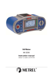
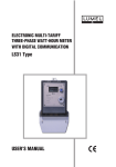
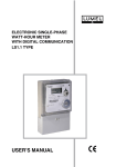
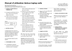
POWER NETWORK PARAMETER METER N13 SERVICE MANUAL POWER NETWORK PARAMETER METER - N13 SERVICE MANUAL CONTENTS 1. 2. 3. 4. 5. APPLICATION and PROPERTIES............................................ 3 METER SET............................................................................... 4 BASIC REQUIREMENTS - SAFETY INFORMATION............... 4 ASSEMBLY................................................................................ 6 METER DESCRIPTION.............................................................. 7 5.1. Measured and calculated quantities by the meter............... 7 5.2. Inputs, outputs, interface...................................................... 8 5.2.1 Current inputs.............................................................. 9 5.2.2 Voltage inputs.............................................................. 9 5.2.3 Analogue output........................................................ 13 5.2.4 Relay output.............................................................. 13 5.2.5 Interface.................................................................... 13 6. PROGRAMMING OF N13........................................................ 14 6.1. Frontal panel...................................................................... 14 6.2. Messages after switching the supply off............................ 14 6.3. Description of the user’s interface..................................... 15 6.4. Accessible measuring quantities........................................ 15 6.5. Setting of the date and time............................................... 16 6.6. Setting of meter parameters.............................................. 17 6.7. Setting of meter output parameters................................... 18 7. 8. 9. 10. 11. RS-485 INTERFACE................................................................ 22 ERROR CODES....................................................................... 24 TECHNICAL DATA................................................................... 25 EXECUTION CODES............................................................... 28 MAINTENANCE AND GUARANTEE....................................... 29 1. APPLICATION and PROPERTIES The N13 panel power network parameter meter is a digital instrument destined to measure all basic parameters in three-phase three-wire or three-phase four-wire, balanced or unbalanced electrical power networks, with the simultaneous display of measured quantities and the digital transmission of their values and their conversion into an analogue standard signal. It can be employed in data acquisition networks or can be used as a single meter instead of many different meters used till now: ammeters, voltmeters, wattmeters, warmeters, frequency meters, phase meters and others. This parameter meter enables the control and optimization of power electronic devices, systems and industrial installation. This parameter meter ensures the measurement of: rms voltage and current, active, reactive and apparent power, active, reactive and apparent energy, power factors, frequency, relative harmonics content of voltage and current, e.g. 15-minutes mean active power. Voltages and currents are multiplied by given voltage and current ratios of measuring transformers. Power and energy indications take into account the value of programmed rations. The value of each measured quantity can be transmitted to the master system through the RS-485 interface. The LPCon program is destined for the configuration of the N13 meter. One must connect the meter through the PD10 converter, to the PC computer. The value of each chosen quantity can be additionally transmitted by means of a standard current signal, the relay output can be used to signal exceedings of chosen quantities. Measurements are carried out by the sampling method of voltage and current signals. 2. METER SET The meter set includes: - N13 parameter meter1 pc - service manual1 pc - guarantee card1 pc - holders to fix the meter in the panel2 pcs 3. BASIC REQUIREMENTS, SAFETY INFORMATION Symbols located in this service manual mean: WARNING! Warning of potential, hazardous situations. Especially important. One must acquaint with this before connecting the meter. The non-observance of notices marked by these symbols can occasion severe injuries of the personnel and the damage of the meter. CAUTION! Designates a general useful note. If you observe it, handling of the meter is made easier. One must take note of this when the meter is working inconsistently to the expectations. Possible consequences if disregarded. In the security scope the meter meets the requirements of the (EN 61010-1) standard. Remarks concerning the operator safety: 1. General The N13 parameter meter is destined to be mounted on a panel. Non-authorized removal of the required housing, inappropriate use,incorrect installation or operation creates the risk of injury to personnel or damage to equipment. For more detailed information please see the service manual. All operations concerning transport, installation, and commissioning as well as maintenance must be carried out by qualified, skilled personnel and national regulations for the prevention of accidents must be observed. According to this basic safety information, qualified, skilled personnel are persons who are familiar with the installation, assembly, commissioning, and operation of the product and who have qualifications necessary for their occupation. 2. Transport, storage Please observe the notes on transport, storage and appropriate handling. Observe the climatic conditions given in Technical Data. 3. Installation The meters must be installed according to the regulation and instructions given in this service manual. Ensure proper handling and avoid mechanical stress. Do not bend any components and do not change any insulation distances. Do not touch any electronic components and contacts. contain electrostatically sensitive components, which can easily be damaged by inappropriate handling. Do not damage or destroy any electrical components since this might endanger your health! Before connecting the meter to the power, one must check the correctness of the mains cable connection. Before the removal of the meter housing, one must disconnect the supply and the measuring circuits. The removal of the housing during the guarantee period causes its cancellation. Meters 4. ASSEMBLY The N13 meter is adapted to be mounted into panels and cubicles by means of 2 holders according the fig.1. The meter housing of 96 ´ 96 ´ 70.5 mm dimensions is made of a sellextinguishing plastics. At the rear side of the meter there are terminal strips which enable the connection of up to 2.5 mm2 conductors. One must prepare a 91+0.5 ´ 91+0.5 mm hole in the panel which the thickness should not exceed 6 mm. The meter must be introduced from the panel front with the switched off supply. After its insertion, fix the meter by means of two holders. Fig.1 NA13 meter dimensions 5. METER DESCRIPTION 5.1. Measured and calculated values by the meter The N13 parameter meter enables the measurement and visualisation of over 30 power energy quantities: Measured quantities Phase voltages Phase-to-phase voltages Line currents Mean line current Active power Reactive power (inductive, capacitive) Apparent power Active energy (total, developped, received) Reactive energy (inductive, capacitive) Apparent energy Power factor cos Single-phase parameters Three-phase parameters U1, U2, U3 U12, U23, U31 I1, I2, I3 I P1, P2, P3 Q1, Q2, Q3 S1, S2, S3 P Q (QL, QC) S PF1, PF2, PF3 EnQ (EnQ_L, EnQ_C) EnS PF EnP (EnP_i, EnP_e) tg1, tg2, tg3 Tg Current THD THD_I1, THD_I2, THD_I3, Voltage THD THD_U1, THD_U2, THD_U3, Power factor tg Frequency F 15 minutes’ mean active power Pav Current in the neutral wire In 5.2. Inputs, outputs, Interface 5.2.1. Current inputs All current inputs all galvanically insulated (internal current transformers). The value on current inputs is automatically calculated in relation to the introduced external current transformer ratio. Current inputs are defined in the order as 1 A or 5 A. 5.2.2. Voltage inputs The quantity on voltage inputs is automatically calculated in relation to the introduced external voltage transformer ratio. Voltage inputs are defined in the order as 3 ´ 57.7/100 V, 3 ´ 230/400 V or 3 ´ 400/690 V Connection diagrams of the meter in a three-phase network Fig. 2a Direct measurement in a three-phase network Fig. 2b Semi-indirect measurement in a three-phase network Fig. 2c Indirect measurement with the use of 2 current transformers and two or three voltage transformers in a three-phase network 10 Connection diagrams of the meter in a four-wire network Fig. 3a Direct measurement in a four-wire network Fig.3b Semi-indirect measurement in a four-wire network 11 Fig. 3c Indirect measurement with the use of three current transformers and two or three voltage transformers in a four-wire network 12 5.2.3. Analogue outputs We can convert quantities from the table 1 into a standard analogue current signal in the range - 20 mA...0...20 mA. The scaling of the measured quantity and also the value of the current signal are realised. 5.2.4. Relay output The internal relay signals the exceeding state of programmed ranges of the chosen quantity. Set of quantities for the analogue and relay output. Table 1 Quantity Phase voltages U1,U2,U3 Lower range value for outputs Upper range value for outputs 1 V... 930 kV 1 V... 930 kV Phase-to-phase voltages U12, U23, U31 2 V... 1,6 MV 2 V... 1.6 MV Phase currents I1, I2, I3, I 0.01A... 45 kA 0.01A... 45 kA - 220...0...220 GW* - 220...0...220 GW Active power P1, P2, P3, P Reactive power Q1, Q2, Q3, Q - 220...0...220 GVar* - 220...0...220 GVar Apparent power S1, S2, S3, S - 220...0...220 GVA* -220...0...220 GVA Power factor PF1, PF2, PF3, PF - 1.00...0...1,000 - 1.00...0...1.000 Power factor tg1, tg2, tg3, tg - 99.9...0... 99.99 - 99.9...0...99.99 Frequency f 0. 20... 100 Hz 0. 20... 100 Hz * Multiplier Giga - is shown on the display simultaneously by lighting of the symbol Kilo and Mega 5.2.5. Interface The meter can communicate with the main system by means of the RS-485 interface with the MODBUS transmission protocol. 13 The converter RS-485/RS-232 (e.g. PD10 type from LUMEL S.A.) or the RS-485 interface card is necessary to connect the meter with a computer Fig. 4 Connection of meters with RS-485 interface to a PC. Note: One can extend the network up to 247 devices. After each 31 devices, one must install a PD51 repeater in series which enlarges the possibilities of the network by 31 successive address numbers and increases the installation distance by ca 1000 m. 14 6. PROGRAMMING OF N 13 6.1. Frontal panel Marker of network type Fields of units and symbols Fields of phase quantities Field of three-phase quantities Cancellation key (ESC) Decimal point change key Value increasing key Acceptation key (ENTER) Fig. 5 Frontal panel 6.2. Messages after switching the supply on After switching the supply on, the meter carries out the test of displays and displays the current version of the program. 15 Where: h.x.xx is the number of the current version of the program or the number of the custommade execution. Fig. 6 Message after switching the supply on Note: If at the moment of the start, the message UnCx (x = I,U,A) appears on the displays, one must contact an authorized service. 6.3. Description of the user’s interface In the measuring mode, quantities are displayed according settled tables. The quantity in the tables and accessible parameters depend on the kind of connected power network. The pressure of the key (top) causes the transition between displayed single-phase quantities. The pressure of the key (left) causes the transition between displayed three-phase quantities. The display of phase and phase-to-phase quantities is independent. 16 6.4. Accessible measuring quantities L1 U1 I1 L2 U2 I2 L3 U3 I3 THD for phase currents THD for phase voltages Phase-to-phase voltages Reactive power to active power ratios Active power factors Phase apparent powers Phase reactive powers Phase active powers Phase currents Phase voltages Accessible phase quantities for a four-wire network P1 Q1 S1 PF1 TG1 U12 THDU1 THDI1 P2 Q2 S2 PF2 TG2 U23 THDU2 THDI2 P3 Q3 S3 PF3 TG3 U31 THDU3 THDI3 Accessible phase quantities for a three-phase network. Phase currents L1 L2 L3 Phase-to phase voltages I1 I2 I3 U12 U23 U31 S PF tG F Pau ENP ENQ Current in the neutral wire Reactive energy Active energy 15 minutes’ mean active power Frequency Q Reactive power to active ratio Mean reactive power P Mean power factor Mean active power 3L I Mean apparent power Mean current Three-phase and mean quantities for 3 and 4-wire networks. IN 17 Fig. 7 Working modes of N13 parameter meter 18 Settings The entry into the programming mode proceeds through the holding of the (enter) key during ca. 3 s. The entry into the programming mode is protected by the access code. The code is introduced for all parameters. In case of lack of code the program transits at once in the programming option. The SET inscription (column 1) and symbols of each levels: T, S, O are displayed. Fig. 8 Setup menu 6.5. Setting of the date and time Mode: time Table 2 Parameter name Default value Change range 2002... 2082 1... 12 1... 31 0... 23 0... 59 Year Month Day Hour Minute After entry into the SETUP procedure we choose the t mode by means of the key (top) and accept by means of the key (enter) y y y y m m d d Where: yyyy - year mm - month dd - day (enter) h h m m s s hh - hour mm - minutes ss - seconds 19 We settle values by means of keys (top) and (left): i.e. we choose the position of the decimal number with the key (left) and the value of the number with the key (top).The active position is signalled by the cursor. The value is accepted by the key (enter) or cancelled by pressing (ESC). After the parameter dd (day), the successive pressure causes the transition to set hours and minutes. The second counter is reset to zero after the minutes, after a successive pressure of the key (enter). For a precise measurement of time one must wait till the full minute and press (enter). 6.6. Setting of meter parameters Mode: Parameters - setup Table 3 Parameter name Displayed Assumptive quantity quantity Change range Default setting dEF N Y/n Input 3 - 4 4 3... 4 Current transformer ratio tr_I 1 1... 9000 Voltage transformer ratio tr_U 1 1... 4000 Cancellation of mean power PA_0 n Y/n Mean power interval (min) PA_t 15 15, 30, 60 Mean power synchronization PA_S N Y/n brt 15 0..15 SECU 0000 0000... 9999 Display brightness Change of the access code The entry into the Parameter mode is protected by the access code, if it is different from zero. In case of the code 0000, the inquiry about the password is omitted. If the access code is different from zero and the user does not introduce the correct code, only the review of parameters is possible. In case of introducing a value over the range, after accepting, the value is set on the upper limit range. 20 6.7. Setting of meter output parameters Mode: Output Parameter name Address of the meter in the network 1) Relay output Analogue output Displayed quantity Assumptive value Addr 1 Range change 0... 247 Baud rate [kbd] bAUd 19.2 k 4800 9600 19200 Mode of the protocol trYb OFF OFF A8n1 A7E1 A7o1 r8n2 r8E1 r8o1 r8n1 Quantity on the relay output 1) 1) Table 4 A_n OFF Tab. 5 Switch-on value in % of the nominal range A_on 101.0 - 120.0...0...120.0 Switch-off value in % of the nominal range A_of 99.0 - 120.0...0...120.0 Delay in the alarm action [s] A_dt 0 0... 100 Quantity on the continuous output 1) Ao_n OFF Tab. 5 Lower value of the input range in % of the nominal range AoIL 0 - 120.0...0...120.0 Upper value of the input range in % of the nominal range AoIH 100 - 120.0...0...120.0 Lower value of the output range (mA) AoOL 4 - 20...0...20 Upper value of the output range (mA) AoOH 20 - 20...0...20 Energy Cancelation En_0 0 Y/n In case of the off or zero quantity value in these quantities, other common output parameters will not be displayed. 21 Outputs are active if a value different from zero (off) was assigned to them. Relay and analogue outputs are not connected with the displayed quantities on the page. In case of negative numbers the introduction of minus follows after the cursor transition on the position 4 (thousands’ number) and pressing the key (top). Example of programming: Set the continuous output on the input range 180... 220 V of the U1 voltage on the output range 4... 20 mA. Check the percentage participation of the signal in the whole nominal range. E.g. 230/400 V 230 V - 100% 230 - 100% 180 V - x % 220 - x % x1 = 180 V • 100% 230 V x2 = 220 V • 100% 230 V X1 = 78% of the input range. X2 = 96% of the input range We assign U1 for the Ao_n parameter AoIL = 78 AoIH = 96 AoOL = 4 AoOH = 20 In case of using external transformers, ratios are taken in consideration in the calculation formula. E.g. *TrU 230 = 100% 22 Table 5 Item Symbol Unit Quantity name 1 2 3 4 5 6 7 U1 I1 P1 q1 S1 PF1 tG1 V A W Var VA Voltage of L1 phase Current of L1 phase Active power of L1 phase Reactive power of L1 phase Apparent power of L1 phase Active power factor of L1 phase Ratio of reactive to active power of L1 phase 8 9 10 11 12 13 14 15 16 17 18 19 20 21 22 23 24 25 26 27 28 29 30 31 32 U2 I2 P2 q2 S2 PF2 tG2 U3 I3 P3 q3 S3 PF3 tG3 I P q S PF tG F U12 U23 U31 PAr V A W Var VA V A W Var VA A W Var VA Hz V V V W Voltage of L2 phase Current of L2 phase Active power of L2 phase Reactive power of L2 phase Apparent power of L2 phase Active power factor of L2 phase Ratio of reactive to active power of L2 phase Voltage of L3 phase Current of L3 phase Active power of L3 phase Reactive power of L3 phase Apparent power of L3 phase Active power factor of L3 phase Ratio of reactive to active power of L3 phase Mean phase current Mean 3-phase power Reactive 3-phase power Apparent 3-phase power Mean active power factor Mean ratio of reactive to active power Frequency L1- L2 phase-to-phase voltage L2- L3 phase-to-phase voltage L3- L1 phase-to-phase voltage Mean power (e.g. 15 min.) 23 7. RS-485 INTERFACE In executions with interface the meter has the possibility to communicate with a PC through the RS-485 line. In the N13 meter, data are inserted in 16 and 32-bit registers. Process variables and meter parameters are placed in the address space of registers in a way depending on the type of the variable value. In the 16-bit register, bits are numbered from the youngest to the oldest (b0-b15). 32-bit registers include numbers of the float type in the IEEE-745 standard. The register map is divided into the following areas. Address range Value type 4000 - 4021 Integer (16 bit) 7000 - 7068 Float (32 bit) The value is placed in two succesive 16-bit registers. Registers are only for readout. 7500 - 7696 Float (32 bit) Value inserted in one 32-bit register. The register description is included in the table 7. Registers for readout. It. Address Symbol 1 4000 2 3 4 5 6 7 8 9 24 4001 4002 4003 4004 4005 4006 4007 4008 Tr_I Tr_U 3-4 P_A0 P_AU P_AS brt A_n A_on Description Value inserted in one 16-bit register. The register description is included in the table 6. Registers for recording and readout. Table 6 Range 1... 9000 1... 4000 0,1 0,1 0,1,2,3 0,1 0...15 0,1...33 - 120...0...120 Description Ratio of the current transformer Ratio of the voltage transformer Choice of network type: 3 or 4-wire Cancellation of mean power Interval of mean power O-off, 1-15; 2-30; 3-60 Synchronization with RTC Display brightness Quantity on the relay output Lower switch-on value Table 6 (continuation) 10 4009 A_oF 11 4010 A_dt - 120...0...120 Upper switch on value 0...100 Delay of the alarm switch on 12 4011 Ao_n 0,1...33 Quantity on the analogue output 13 4012 AoIL - 120...0...120 Lower threshold of the input quantity 14 4013 AoIH - 120...0...120 Upper threshold of the input quantity 15 4014 AoOL - 20...0...20 Lower threshold of the output scaling [mA] 16 4015 AoOH - 20...0...20 Upper threshold of the output scaling [mA] 17 4016 YeAr 2002... 2084 Year 18 4017 MonDay 19 4018 HourMin 20 21 4019 4020 ALm En_0 Month*100 + day Time in the format Hour*100 + minutes 0. 1 State of the relay output Cancellation of watt-hour meters Table 7 It. Register Symbol Unit address Quantity name 1 7500 U1 V 2 7501 I 1 A L1 phase voltage L1 phase current 3 7502 P 1 W L1 phase active power 4 7503 q 1 Var L1 phase reactive power 5 7504 S 1 VA L1 phase apparent power 6 7505 PF1 Active power factor of L1 phase 7 7506 tG1 Ratio of reactive to active power of L1 phase 8 7507 U2 V L2 phase voltage 9 7508 I 2 A L2 phase current 10 7509 P 2 W L2 phase active power 11 7510 q 2 Var L2 phase reactive power 12 7511 S 2 VA L2 phase apparent power 13 7512 PF2 L2 Active power factor of L2 phase 14 7513 tG2 Ratio of reactive to active power of L2 phase 25 Table 7 (continuation) 15 7514 16 7515 I 3 A L3 phase current 17 7516 P 3 W L3 phase active power 18 7517 q 3 Var L3 phase reactive power 19 7518 S 3 VA L3 phase apparent power 20 7519 PF3 Active power factor of L3 phase 21 7520 TG3 Ratio of reactive to active power of L2 phase 22 7521 reserved 23 7522 I A Mean phase current 24 7523 P W Active 3-phase power 25 7524 q Var Reactive three-phase power 26 7525 S VA Apparent three-phase power 27 7526 PF 28 7527 tG 29 7528 Freq Hz Frequency 30 7529 U12 V L1-L2 phase-to-phase voltage 31 7530 U23 V L2-L3 phase-to-phase voltage 32 7531 U31 V L3-L1 phase-to-phase voltage 33 7532 reserved 34 7533 Pav W 35 7534 Date: Day, Month 36 7535 Year 37 7536 Time: Hour, Minute 38 7537 Seconds 39 7538 EnP Wh Active energy 40 7539 EnQ Varh Reactive energy 41 7540 EnS VAh 42 7541 THD U1 % THD for phase voltage L1 43 7542 THD U2 % THD for phase voltage L2 44 7543 THD U3 % THD for phase voltage L3 45 7544 THD I1 % THD for phase current L1 26 U3 V L3 phase voltage Mean active power factor Mean ratio of active to reactiver power Mean power (e.g. 15 minutes) Apparent energy Table 7 (continuation) 46 7545 THD I2 % THD for phase current L2 47 7544 THD I3 % THD for phase current L3 Harmonics of phase voltage L1 48...72 7547...7571 H1...H25 (U1) % 73...97 7572...7596 H1...H25 (U2) % Harmonics of phase voltage L2 98...122 7597...7621 H1...H25 (U3) % Harmonics of phase voltage L3 123...149 7622...7646 H1...H25 (I1) % Harmonics of phase current L1 150...174 7647...7671 H1...H25 (I2) % Harmonics of phase current L2 175...198 7672...7696 H1...H25 (I3) % Harmonics of phase current L3 199 7697 In A Current in the neutral wire 200 7698 EnP_i Wh Consumed active energy 201 7699 EnP_e Wh Returned active energy 202 7700 EnQ_L varh Inductive reactive energy 203 7701 EnQ_C varh Capacity reactive energy 204 7702 Q_L var Inductive reactive power 205 7703 Q_C var Capacitive reactive power 8. ERROR CODES Messages about errors can appear during the meter work. The causes of these errors are presented below: Err - when the voltage or current is too small during the measurement: Pf i ,t i below 7% Un, In f below 7% Un THD U Un < Un - 10%Un, lub Un > Un + 12%Un, 55 Hz < f < 45 Hz THD I I < 10% In l The full time interval of the Pau power averaging is not expired. 27 9. TECHNICAL DATA Measuring ranges and admissible basic errors are presented in the table 8 Table 8 Measured quantity Range Basic error Remarks U i voltage 57.7/100 V (Ku=1) 230/400 V (Ku=1) 400/ 690 V (Ku =1) dla Ku1...1,6 MV (0.2% m.v.+0.1% range) Ku = 1...4000 (max 1.6 MV) I i current 1.000 A (Ki=1) 5.000 A (Ki=1) dla Ki1...45 kA (0.2% m.v.+0.1% range) Ki = 1...9000 (max 45 kA) P i active power PAV mean active power Active energy EnP S i apparent power Apparent energy EnS Q i reactive power Reactive energy EnQ 0.0... 999.9 W for Ku1, Ki1 (-)220 GW (0.5% m.v.+0.2% range) 0.0...999.9 VA for Ku1, Ki1 220 GVA (0.5% m.v.+0.2% range) 0.0... 999.9 Var for Ku1, Ki1 (-)220 GVar (0.5% m.v.+0.2% range) - 1.00 ...0.00 ...1.000 1% m.v. 2c Pf=Power factor=P/S t i factor (ratio of reactive power to active power) - 99.9....0....99.9 1% m.v. 2c error in the range - 99.9...0...99.9 f frequency 20.0... 500.0 Hz 0.5% m.v. 0.5...100% 5% m.v. 2c Pf i active power factor THD Ui, THD Ii Where: Ku - voltage transformer ratio Ki - current transformer ratio m.v. - measured value c - less significant display digit 28 -10%Un <Un < 12%Un In > 10% In 47... 52 Hz Power consumption: - supply circuit - voltage circuit - current circuit 12 VA 0.5 VA 0.1 VA Supply 85...250 V d.c. or a.c., 40...400 Hz Display field: Outputs: - analogue output 4 x 4 LED digits, 10 mm high, red or green displays 1 analogue programmed output: -20... 0...+20 mA accuracy: 0.2% - relay output 1 relay output, voltageless make contacts load capacity: 250 V a.c./ 0.5 A a.c. Serial interface RS-485 Transmission protocol MODBUS ASCII and RTU Meter reaction to decays and supply recovery data and meter state preservation during supply decays, (battery support), work continuation after supply recovery Protection degree ensured by the housing: - frontal side - terminal side IP 40 IP 10 Weight 400 g Overall dimensions 96 96 70.5 mm Panel cut-out dimensions 91+0.5 91+0.5 29 Reference conditions and nominal operating conditions: - Input signal: 0...0.02...1.2 In, 0...0.02...1.2 Un, for voltage, current, frequency, power 0...0.02...1.2 In, 0...0.07...1.2 Un, for Pf and t factors, frequency 15...45...65...500 Hz sinusoidal current (THD 8%) - power factor - ambient temperature - relative air humidity - storage temperature - supply - admissible peak factor: - current - voltage - external magnetic field - short duration overload (5 sec): - voltage inputs - current inputs - working position - warm-up time - 1...0...1 0...23...55°C 25...95% (no condensation) - 20...70°C 85... 253 V d.c. or a.c. 40... 400 Hz 2 2 0...40...400 A/m 2 Un (max.1000 V) 10 In any 5 minutes Additional errors in % of the basic error: - from frequency of input signals < 50% - from ambient temperature changes < 50%/10C Electromagnetic compatibility: - immunity - emission acc. EN 61000-6-2 acc. EN 61000-6-4 Safety requirements: acc. EN 61010-1 - insulation ensured by the housing dual - insulation between circuits basic - installation category III - pollution degree 2 - maximal working voltage in relation to earth 600 V a.c. 30 10. EXECUTION CODES AND ORDERING WAY Table 10 NETWORK PARAMETER METER N13 - X. X. X. X. X. XX. X Input current In: 1 A (X/1)................................................................ 1 5 A (X/5)................................................................ 2 on order *.............................................................. 9 Input phase/phase-to-phase voltage Un: 3 57.7/100 V............................................................ 1 3 230/400 V............................................................. 2 3 400/690 V.............................................................. 3 on order *..................................................................... 9 Current analogue output: without analogue output.................................................... 0 with a programmed output - 20... + 20 mA...................... 1 Digital output: without interface.......................................................................0 with RS-485 interface...............................................................1 Display: red digits.........................................................................................1 green digits.....................................................................................2 Kind of execution: standard.............................................................................................. 00 custom-made.......................................................................................XX Acceptance test: without an extra quality inspection certificate............................................. 8 with an extra quality inspection certificate.................................................. 7 acc user’s agreement**.............................................................................. X * After agreeing by the manufacturer ** The execution numbering will be made by the manufacturer. 31 Coding example: The N13 2 2 1 1 2 00 7 code means: input range: 5 A, input voltage: 3 ´ 230/400 V, with a programmed current analogue output: - 20... 20 mA, RS-485 interface, green digits, standard execution, with an extra quality inspection certificate. 11. MAINTENANCE AND GUARANTEE The N13 parameter meter does not require any periodical maintenance. In case of some incorrect unit operations: 1. From the shipping date, during the period given in the annexed guarantee card. One should take the instrument down from the installation and return it to the Manufacturer’s Quality Control Dept. If the instrument has been used in compliance with the instructions, the Manufacturer guarantees to repair it free of charge. 2. After the guarantee period: One should turn over the instrument to repair in a certified service workshop. The disassembling of the housing causes the cancellation of the granted guarantee. Spare parts are available for the period of ten years from the date of purchase. The Manufacturer’s policy is one of continuous improvement and we reserve the right to make changes in design and specifications of any products as engineering advances or necessity requires and revise the above specification without notice. 32 33 34 35 SALES PROGRAM n n n n n n n n n n n n MEASUREMENT DIGITAL and BARGRAPH PANEL METERS CONTROL MEASURING TRANSDUCERS RECORDING ANALOG PANEL METERS (DIN INSTRUMENTS) ANALOG and DIGITAL CLAMP-ON METERS INDUSTRIAL and HOUSEHOLD CONTROLLERS CHART AND PAPERLESS RECORDERS POWER CONTROL UNITS and INVERTERS WATT-HOUR METERS AUTOMOTIVE DASHBOARD INDICATORS ACCESSORIES FOR MEASURING INSTRUMENTS (SHUNTS) MEASURING SYSTEMS (ENERGY, HEAT, CONTROL) CUSTOM-MADE MEASURING ELECTRONIC DEVICES. WE ALSO OFFER OUR SERVICES IN THE PRODUCTION OF: n ALUMINIUM ALLOY PRESSURE CASTINGS n PRECISION ENGINEERING AND THERMOPLASTICS PARTS n PRESSURE CASTING DIES AND OTHER TOOLS n VARIOUS ELECTRONIC SUB-ASSEMBLIES (MSD TECHNOLOGY) QUALITY PROCEDURES: According to ISO 9001 and ISO 14001 international requirements. All our instruments have CE mark. For more information, please write to or phone our Export N13-07C Lubuskie Zak³ady Aparatów Elektrycznych LUMEL S.A. ul. Sulechowska 1, 65-022 Zielona Góra, Poland Tel.: (48-68) 3295 100 (exchange) Fax: (48-68) 3295 101 e-mail:[email protected] http://www.lumel.com.pl Export Department: Tel.: (48-68) 329 53 02 or 53 04 Fax: (48-68) 325 40 91 e-mail: [email protected] 36