1
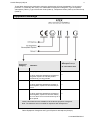
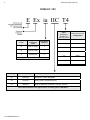
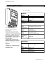
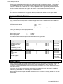
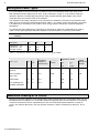
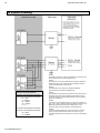
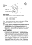
IFD-E(IS)
Intrinsically Safe Flame Detector
User Manual
2
Hochiki Europe (UK) Ltd
General
Description
This Installation Guide gives information on the intrinsically safe (I.S.) version of the flame detectors that
have been approved by BASEEFA (British Approvals Service for Electrical Equipment in Flammable
Atmospheres). The requirements of the European Community Directive 94/9/EC, the ATmosphere
EXplosives ATEX Directive have been met. The approval have been accessed to European Standards
EN 50014, EN 50020 and EN 50284.
The detectors are certified
II 1 G
EEx ia IIC T4 and can be used with all listed gases.
The range comprises single infra-red (IR), dual infra-red (IR²) and triple infra-red (IR³) flame detectors.
The detector housings are available in zinc metal alloy or stainless steel and also stainless steel
(antistatic) glass filled polycarbonate.
The guide also provides information on intrinsic safety, the application, maintenance, installation and
adjustments of the detectors. Reference to other individual detector publications can be made for more
information on none intrinsically safety issues. These publications are available on request.
Introduction to Intrinsic Safety
There are many places where an explosive mixture of air and gas or vapour is or may be present
continuously, intermittently or as a result of an accident. These are defined as hazardous areas by BS
EN 50014:1998, Electrical apparatus for potentially explosive atmospheres – General requirements.
Hazardous areas are common in petroleum and chemical engineering plants and in factories processing
and storing gases, solvents, paints and other volatile substances.
Electrical equipment for use in these areas needs to be designed so that it cannot ignite an explosive
mixture, not only in normal operation but also in fault conditions. There are a number of methods
available to achieve this – oil immersion, pressurised apparatus and powder filling, for example, but the
two most common used are flameproof enclosures and intrinsic safety.
Flameproof equipment is contained in a box so strong that an internal explosion will neither damage the
box nor be transmitted outside the box. The surface must remain cool enough not to ignite the explosive
mixture.
When flameproof equipment is interconnected, flameproof wiring must be used. This method is most
valuable when high power levels are unavoidable but it is not acceptable for areas in which an explosive
gas/air mixture may be continuously present or present for long periods.
For this reason these flame detectors are made intrinsically safe rather than flameproof. Intrinsically safe
equipment operates at such low power and with such small amounts of stored energy that it is incapable
of causing ignition:
In normal conditions
With a single fault (for ib type of protection code)
With any combination of two faults (for ia type of protection code)
In any of these conditions every component must remain cool enough not to ignite gases for which it is
approved. See Table 2
Classification of Hazardous Areas
EN 50014 states that electrical apparatus for potentially explosive atmospheres is divided into:
Group I: Electrical apparatus for mines susceptible to fire damp;
Group II: Electrical apparatus for places with a potentially explosive atmosphere, other than
mines susceptible to fire damp.
2-3-0-809/ISS2/JUL07
Hochiki Europe (UK) Ltd
3
These flame detectors are designed to meet the requirements of Group II apparatus. For the type of
protection “i” intrinsically safe, Group II is subdivided into Equipment Categories, Type of Explosive
Atmosphere (Table 1), Type of Protection Code (Table 2), Temperature Class (Table 3) and Gas Group
(Table 4).
Equipment Markings
Equipment
Category
Type of Explosive
Atmosphere Group II
Definition
G - gas vapour mist
Zone
1
- very high level of protection
in which explosive atmosphere mixtures of
air gases, vapours or mist are present
continuously, for long periods
2
- high level of protection
in which explosive atmosphere mixture of
air and gases, vapours or mist are likely to
occur
3
0
1
- normal level of protection
in which explosive atmosphere mixtures of
air and gases, vapours or mist are unlikely
to occur and if it occurs it will exist only for a
short period
2
These Flame Detectors are suitable for all the above equipment categories.
Note: The detectors are not certified for explosive dust atmospheres.
Table 1Equipment Categories and Type of Explosive Atmosphere (Group II)
2-3-0-809/ISS2/JUL07
4
Hochiki Europe (UK) Ltd
Temperature
Class
Referred to
ambient of
-20°C to +40°C
T6
Type of
Protection
Code
Equipment
Category
ia
Intrinsic safety
1
ib
Intrinsic safety
2
d
Flameproof
3
Code
These Flame Detectors are approved ia.
Table 2 – Type of Protection Codes
Maximum Surface
Temperature
85°C
T5
100°C
T4
135°C
T3
200°C
T2
300°C
T1
450°C
Detectors approved to T4 at 40°C
Table 3 – Temperature Classifications
Gas Group
Representative Gas
Other Gases, Liquids & Vapours
IIC
Hydrogen
Acetylene, Carbon Disulphide
IIB
Ethylene
Diethyl ether, Tetrafluroethylene
IIA
Methane
Butane, Methanol, Petroleum, Propane, Styrene
These Flame Detectors are approved IIC for listed gases in EN 50014.
Table 4 – Subdivisions of Group II Gases
2-3-0-809/ISS2/JUL07
Hochiki Europe (UK) Ltd
5
Intrinsically Safe Product
Technical Data
Mechanical
Housing Material:
See Fig 1
Housing Colour:
Housing
Dimension:
(Excluding Mount)
Cable Gland
Entries:
Die Cast Zinc Alloy
Blue (typical)
Height = 142mm
Width = 108mm
Depth = 82mm
2 X 20mm
Electrical
Fig. 1
Intrinsically Safe Flame Detector
(Alloy Housing)
The flame detectors respond to light
emitted from flames during combustion.
The detectors discriminate between flames
and other light sources by responding only
to low frequency flickering produced by
flames (typically 1 to 15Hz). The detectors
ignore fixed light sources and rapidly
flickering illumination predominantly
produced by lighting.
The flame flicker techniques have the
advantage of still allowing the detection of
flames through a thin layer of oil, water
vapour, ice or dust. This makes these
detectors particularly useful in industrial
applications.
Full details of the principles of operation,
electrical description, and other detailed
technical data are published in the products
individual data sheet.
Supply In:
Voltage
Current
Polarity sensitive
Optional Input:
Voltage
Current
Polarity sensitive
Optional Output:
Voltage
Current
Optional Relays
Contact Ratings:
Voltage
Current
Resistive Loads Only
Terminals 1(+) & 2(-)
14 to 30Vdc
2 to 30mA See datasheet for detail
Terminals 3(+) & 4(-)
14 to 30Vdc
40µA typ. @ 24V IN
Terminals 3(+) & 4(-)
0V to Supply In (O/C)
2.4mA typ. Internally Limited
Terminals 3 to 8
30Vdc. Max.
1 Amp. Max.
Environmental
Operating Ambient
Temperature:
Check detector
limits
ATEX
Approval Category
-20°C to +40°C(T4)
-20°C to +85°C(T3)
II 1 G
CENELEC / IEC
Marking
EEx ia IIC T4
Apparatus
Certificate Number
BAS02ATEX1001
2-3-0-809/ISS2/JUL07
6
Hochiki Europe (UK) Ltd
System Design
Engineers familiar with codes of practice for hazardous area systems should only undertake the design of
an intrinsically safe fire detection system. In Europe the standard is EN 50014, Electrical apparatus for
potentially explosive atmospheres – General requirements.
The fire detector performance is the same as the standard none intrinsically safe counterparts.
Performance information given in standard product guides is therefore applicable to the intrinsically safe
range.
The BASEEFA certification of the intrinsically devices covers their characteristics as components of an
intrinsically safe system. This indicates that the flame detectors can be used with a margin of safety in
such systems.
In safe area (standard) applications it is some times desirable to connect the wiring as a loop, with both
ends terminated at the control panel. In the event of an open-circuit fault it is then possible to drive both
ends simultaneously. In a hazardous area it is not possible to use a loop configuration because the
potential to feed power from each end of the loop would double the available energy in the hazardous
area and contravene the energy limitations of the intrinsically safe certification. All circuits must therefore
be connected as spars from the safe area or as radial connections from the control panel.
Types of Safety Barrier
The system configuration can for three types of safety barrier, each of which has its own advantages and
disadvantages. A brief outline of the characteristics is given below.
Single Channel 28V/300Ω Barrier
This is the most basic type of barrier and therefore the lowest cost. Being passive devices, they also
impose the minimum of restrictions on the operation of the flame detectors. Thus, single channel barriers
are available either as positive or negative polarity where the polarity refers to the polarity of the applied
voltage relative to earth. The significance of this is that one side of the barrier must be connected to a
high-integrity (safety) earth. Although this connection has no effect on the operation of the flame detector
and is not needed for their correct operation, it may not be acceptable to the operation of the control and
indicating equipment. This is particularly true if the control equipment incorporates earth-leakage
monitoring and even without this feature the earthing of the loop may cause unwanted cross-talk between
loops.
If the earth connection is not acceptable then the A.C. or isolating barriers should be used.
Star-connected A.C. Barrier
A.C. barriers are also passive devices and must still be connected to a high-integrity safety earth.
However, they are designed to allow either positive or negative voltages with respect to earth and under
normal conditions provide a connection to earth via a reverse-diode, rather than directly.
The disadvantage of this type of barrier is that the end-to-end resistance is nominally 1200ohms
compared with the 300 ohms of the single channel type. This high resistance results in an extra voltage
drop in the circuit. This type of barrier is not recommended for general use
Galvanically Isolated Barrier
Galvanically isolated barriers (also know as transformer isolated barriers) differ from conventional shunt
zener barriers in that they provide electrical isolation between the input (safe area) and the output
(hazardous area). This is achieved by the use of a D.C./D.C. converter on the input side, which is
connected to the hazardous area through a voltage and power limiting resistor/zener combination similar
to a conventional barrier.
The galvanic isolation technique means that the circuit does not need a high integrity (safety) earth and
that the intrinsically safe circuit is fully floating. Earth leakage problems for control and indicating
equipment are therefore eliminated if this type of interface is used.
2-3-0-809/ISS2/JUL07
Hochiki Europe (UK) Ltd
7
Galvanically isolated barriers are widely used with conventional flame detector systems. If the system is
of an addressable type with signal pulses on the supply lines then the response time of most standard
barriers will be too slow to allow their use. In these applications special galvanically isolated barriers are
required that can freely transmit the required protocol pulses without introducing severe voltage drops.
These interfaces are available as single or dual channel versions and are recommended for any
application in which direct earth connections are not acceptable.
The galvanically isolated barrier is a two-wire device which does not need an external power supply.
Current drawn from the detector supply connections by the barrier itself is less than 500µA
Approved Safety Barriers
For systems a generic specification for the barriers is as follows:
Any shunt zener diode safety barrier certified and approved to meet the ATEX Directives or CENELEC /
IEC standards.
II (1) G
ATEX group and category
CENELEC / IEC marking
[EEx ia] II C (associated apparatus)
Having the following or lower output parameters:
Max. output volts
Uo :
= 30V
Max. output current
Io :
= 100mA
Max. output power
Po :
= 0.65W
A number of barriers meet this specification and examples are given below:
Supplier
Type
Polarity
Mounting
Technique
Pepperl & Fuchs Ltd
77 Ripponden Road
Oldham
Lancashire OL2 8PF
United Kingdom
www.pepperl-fuchs.com
Z728
Z779
Z828
+
+
-
DIN rail
DIN rail
DIN rail
Shunt 300Ω
Shunt 300Ω X 2
Shunt 300Ω
DIN rail
DIN rail
Galvanic X 1
Galvanic X 2
MTL
Power Court
Luton
Bedfordshire LU1 3JJ
United Lingdom
www.mtl-inst.com
MTL7028+
MTL7728+
MTL7779+
+
+
+
DIN rail
DIN rail
DIN rail
Shunt 300Ω
Shunt 300Ω
Shunt 300Ω X 2
MTL7706+
+
DIN rail
Active 300Ω,
4-20mA output
KFD0-CS-Ex1.51
KFD0-CS-Ex2.51
Safety Earth
Single channel and star connected A.C. safety barriers must be connected to a high integrity earth by at
least one and preferably two copper cables, each of cross sectional area of 4mm² or greater. The
connection must be such that the impedance from the connection point to the main power system earth is
less than one ohm.
Intrinsically safe circuits in the hazardous area should be insulated from earth and must be capable of
withstanding a 500V RMS A.C. test voltage for at least one minute.
When using armoured or copper sheathed cables, the armour or sheath is normally isolated from the safe
area busbar.
2-3-0-809/ISS2/JUL07
8
Hochiki Europe (UK) Ltd
Wiring and Cable Types
It is not permitted to connect more than one barrier circuit in the hazardous area to any other circuit.
Both separate and twin cables may be used. A pair contained in a type ‘A’ or ‘B’ multicore cable (as
defined in clause 5.3 of EN50 039) may also be used, provided that the peak voltage of any circuit
contained within the multicore does not exceed 60V.
The capacitance and either inductance or the inductance to resistance (L/R) ratio of the hazardous area
cable must not exceed the parameters specified in Table 6. The reason for this is that energy can stored
in a cable and it is necessary to use cable in which energy stored is insufficient to ignite an explosive
atmosphere.
To calculate the total capacitance or inductance for the length of cable in the hazardous area, refer to
Table 7, which gives typical per kilometre capacitance and inductance for commonly used cables.
Note: The flame detectors have zero equivalent inductance (Li = 0) and a 0.03μF capacitance (Ci =
0.03μF).
Gas group
IIA
IIB
IIC
Capacitance μF
Inductance mH
L/R ratio μH/ohm
2.15
33.6
440
0.65
12.6
165
0.083
4.2
55
Table 6 – 28V Barrier, Maximum Permissible Stored Energy in Cables
Cable Type
Core
Size
mm²
Conductor
resistance
ohm/km/core
MICC Pyrtenax
light duty
2
1.5
12.1
MICC Pyrotenex
heavy duty
2
1.5
12.1
Pirelli FP200
all
1.5
12.1
PVC sheathed and
Insulated to BS6004
all
1.5
12.1
Capacitance µF/km
Inductance
mH/km
Sheath
Resistance
ohm/km
core
to
core
core
to
sheath
0.534
0.19
0.21
2.77
0.643
0.13
0.17
1.58
0.08
0.15
0.77
0.09
Table 7 Examples of electrical characteristics of cables commonly used in fire protection systems
Maximum Loading of IS Circuit
Because of the finite resistance of the safety barrier, there will be a limit to the current drain which can be
tolerated before the voltage on the circuit falls outside the specified limits for the IS detector. The standing
current for the detectors can be calculated by the sum of the individual selected detector currents as
given in the detector data sheet. This may limit the maximum number of detectors per barrier to two or
three.
2-3-0-809/ISS2/JUL07
Hochiki Europe (UK) Ltd
9
Installation
It is important that the IS detectors are installed in such a way that all terminals and connections are
protected to at least IP20 with the detector cover fitted. The earth bonding terminals are provided for
convenience where continuity of a cable sheath or similar is required
Service & Repairs
Servicing of IS flame detectors may be carried out only by a BASEEFA or equivalent authorised body. In
practical terms this means that IS flame detector may be serviced only at the manufactures factory.
Servicing of the fire protection system should be carried out as recommended by the local regulation in
force.
2-3-0-809/ISS2/JUL07
10
Hochiki Europe (UK) Ltd
IS System Drawing
NOTE 1
Each Barrier fed circuit must be a separate circuit and must not
be connected with any other electrical circuit.
NOTE 2
The electrical circuit in the hazardous area must be capable of
withstanding an AC test voltage of 500 volts RMS to earth or
frame of the apparatus for one minute.
NOTE 3
The installation must comply with national installation
requirements (for example to EN 60079-14)
Detector Input Parameters
Terminal 1 with respect to terminal 2
Terminal 3 with respect to terminal 4
Ui = 30V
Ii = 100mA
Pi = 0.65W
Ci = 0.03µF
Li = 0
Terminal 5 with respect to terminal 6
Terminal 7 with respect to terminal 8
Ui = 30V
Ii = 100mA
2-3-0-809/ISS2/JUL07
NOTE 4
The capacitance and either the inductance or the inductance to
resistance (L/R) ratio of the hazardous area cables must not
exceed the maximum permissible parameters for the required
groups IIA, IIB and IIC.
NOTE 5
The cable may be separate cables or a twin pair contained in a
type ‘A’ or a type ‘B’ multicore cable (as defined in clause 5.3 of
EN50 039). Provided that the peak voltage of any circuit
contained within the muticore does not exceed 60 volts.
NOTE 6
If required a loading resistor of not less than 3k 0.5 watt and
having a surface area between 20cm² and 10cm² may be
connected between the terminals of any circuit, but not between
circuits.
Hochiki Europe (UK) Ltd
11
Hochiki Europe (UK) Ltd
Grosvenor Road, Gillingham Business Park,
Gillingham, Kent, ME8 0SA, England
Telephone: +44(0)1634 260133 Facsimile: +44(0)1634 260132
Email: [email protected]
Web: www.hochikieurope.com
Hochiki Europe (UK) Ltd. reserves the right to alter the specification of its products from time to time without notice. Although every effort
has been made to ensure the accuracy of the information contained within this document it is not warranted or represented by Hochiki
Europe (UK) Ltd. to be a complete and up-to-date description. Please check our web site for the latest version of this document.
2-3-0-809/ISS2/JUL07