1
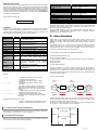
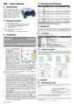
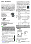
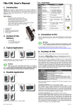
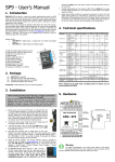
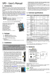
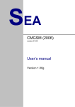
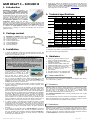
GSM RELAY 3 – SCHUKO B 8. 1. Introduction GSM RELAY 3 - SCHUKO B (GSM RELAY for short) is device for remote control of 230 VAC outlet via SMS in GSM network, which is easy to install and operate. Just insert SIM card, plug the GSM RELAY into the power outlet (230 VAC), connect your electrical appliance and send SMS to switch ON or OFF the output power outlet on the GSM RELAY. GSM RELAY has more useful functions like temperature regulation using an external temperature sensor, remote ON and OFF switching of the connected appliance just by “ringing” from your mobile phone, GSM RELAY can send an alarm SMS when temperature limit is exceeded. GSM RELAY has two digital outputs, two temperature inputs and two digital inputs which can be configured for alarm functions. GSM RELAY can control two independent electrical circuits in a building e.g. circuit of an accumulator stove and circuit for garage gate control. 4. Technical specifications Parameter Dimensions Supply Digital inputs Digital outputs 2. Package content 1 1 1 2 1 1 1 1 pc pc pc pcs pc pc pc pc Default factory setting of the GSM RELAY can be recovered by an SMS in form 1234 FACTORY. Your setting can be then restored from PC via USB cable using backup configuration created by SeaConfigurator program. This configuration program is free to download from web pages www.seapraha.cz (fill in here the word "configurator" into the search field). GSM RELAY 3 – SCHUKO B (order code GSM-R3-ZASB-EN) temperature sensor (-20 °C to +50 °C; order code GSM-C-T2) cable micro USB (order code HW-11.92.8750) connector ETB4702G00 connector 15EDGK3.81-04P connector ETB4706G00 screwdriver BERNSTEIN printed documentation Analog inputs Temperature Humidity Width Length Depth Voltage Current Voltage Current Symbol W L D VCC MIN. TYP. 65 140 95 180 230 11 INPUT 1, INPUT 2 VIN 3 12 IIN 3.5 Mains OUTLET – OUTPUT NO. 0 (Power VOUT 210 230 MAX. Unit mm mm mm V AC mA 250 30 30 V DC mA DC Relay) Voltage 250 V AC Max. Current IOUTmax(R) 10 A (resistive load) Max. Current IOUTmax(I) 4 A (inductive load) OUTPUT 3, OUTPUT 4 (Semiconductor switch OPTO-MOS) Voltage VOUT 5 230 250 V AC (400) (V DC) Current IOUT 90 mA AC (130) (mA DC) *1) 2 x temperature sensor GSM-C-T2 , Accuracy in range 0 to 30°C ... 1°C Temperature -50 +150 °C *1) *1) range *1) Storage tSTG -40 +85 °C Operational tA -20 +45 °C Relative RHmax 90 % GSM RELAY can be used inside building only! 3. Installation 1. To operate the GSM RELAY a SIM card of any GSM operator is necessary. SIM card must be functional, active and must have PIN code turned off. Also some credit is necessary if SIM card is pre-paid. Before inserting the SIM card into the GSM RELAY device, it is necessary to turn off setting of the “PIN code”! Insert the active SIM card (= at least one call was made) to any mobile telephone and turn off the requirement of setting the PIN. On most mobile telephones, this option can be found in menu “Setting the telephone protection”. or “Setup -> Security -> PIN control”. WARNING! Any connection to power supply higher than 12 V (except 230 V AC mains outlet on the main panel of GSM RELAY) must be done by qualified personnel only! 2. Insert this prepared SIM card (cut corner first) into the GSM RELAY device. The SIM card holder is located on the down side of the device. The proper insertion is indicated by a slight mechanical click noise. To remove the SIM card press the SIM card in direction into the GSM RELAY until mechanical click. The SIM card can be then freely removed. 3. Now you can plug the GSM RELAY into a standard single-phase 230 V AC wall outlet. In case the power supply is correct, the green LED diode POWER goes on. Simultaneously, blue LED “GSM” flashes several times and then after about 1 minute, starts flashing with a period of 2 sec. 4. For the first tests of GSM RELAY the connection of inputs and outputs is not important. (Please keep in mind that the devices connected to OUTPUTS will be switched on during tests!) 5. Press the pushbutton OUTLET to test the GSM RELAY. The green LED diode for OUTLET lights ON. Send an SMS from mobile phone (which will be mainly used to control the GSM RELAY) in form 1234 Y0 OFF to the telephone number of the SIM card inserted into the GSM RELAY. This will switch off the plugged appliance. The green status LED for OUTLET goes OFF. Simultaneously, the GSM RELAY automatically sends a confirmation SMS message on performing the operation. The password 1234 can be changed later in configuration. The GSM RELAY reacts on the SMS text message from any telephone as long as the access password matches. The very first one (the sender of the first valid SMS message) will be remembered as master and will receive SMS messages about events on GSM RELAY. This user can also control OUTPUT 4 by “ringing” on the device. 6. 7. *1) Temperature sensor GSM-C-T2 has temperature range -20 °C to +50 °C. Use other type of sensor for wider range of temperatures. 5. Hardware 1) Mains 230 V AC OUTLET (OUTPUT 0 (Y0)) for supply of connected electrical appliance 2) Pushbutton OUTLET for 230 VAC outlet control and indication LED diode 3) Indication LED diodes POWER, ALARM, GSM 4) Indication LED diodes INPUT 1 (X1), INPUT 2 (X2) 5) Connector for temperature sensors (T5, T6) 6) INPUT 1, 2 connectors (X1, X2) & supply +4V DC 7) OUTPUT 3, 4 connectors (Y3, Y4) 8) SIM card holder 9) Micro USB connector for PC configuration cable 10) Pushbuttons OUTPUT 3, 4 and indication LEDs 5.1 Power outlet 230 VAC 1 2 3 10 4 9 5 8 6 7 Power outlet 230 VAC is for connection of controlled electrical appliance (Max. 2300 W/ 10 A, resistive load) e.g. radiator. 5.2 Connectors GSM RELAY enables to connect 2 external logical inputs, 2 external logical outputs, 230 VAC power inlet and 2 external temperature sensors GSM-C-T2 (or similar types with wider range of temperatures). The line length of a connected external temperature sensor is not limited but the wire has a certain resistance which influences the measured temperature (16 Ohms means 1 °C). Read Technical specifications before connecting external devices! Don’t overload inputs and outputs! The recommended type of relay for connection of more appliances is GSM-RELE-OUT. When using the GSM RELAY for a gate control by a “ringing”, it’s possible to connect output 3 and COM directly with a pushbutton of the gate control. Try “ringing” on device. You can make pulse on OUTPUT 4 for approx. 4 seconds by calling to GSM RELAY (with default factory setting). The device hangs up the call and makes pulse on the OUTPUT 4. This pulse can be used for example for opening entrance gate. To test this function call from the phone (which was used to send the first test SMS to switch off the OUTLET). The pulse is indicated by green LED. 5.3 Pushbuttons Try regulation. You can send SMS in form of 1234 Y0 REG 25 to command the device to maintain temperature to 25°C. The range of regulation is between 0°C and +55°C. Regulation can be canceled by SMS with command 1234 Y0 OFF or by pushbutton. By default the regulation of OUTLET depends on temperature sensor connected to analog INPUT T5. Note: Pushbutton cancel the function “temperature regulation”, but does not influent “advanced” functions like “nonfreezing temperature keeping” and “alarm” functions. Use Sea Configurator to cancel these “advanced” functions. gsm-r3-zasb user's manual en v1-14.doc / 2011-10-24 GSM RELAY has three pushbuttons for local control of each output (230 V AC OUTLET, OUTPUT 3 (Y3) and OUTPUT 4 (Y4). The pushbutton toggles the state of the output. Page #1 of 4 SIM CARD U S B OUTPUT4 8 V DC to 230 V AC OUTPUT3 8 V DC to 230 V AC Configuration of GSM RELAY from PC via USB cable The configuration (parameter setting) of GSM RELAY can be changed using program Sea Configurator, which can be free download including the user’s manual from web site www.seapraha.cz (type in there the word “configurator” into the search field). E.g. GSM RELAY can be setup to inform of the 230 VAC power failure or restoration via SMS or by ringing. GND +4V DC temperature INPUT T6 SOCKET 230 V AC / 10 A (=OUTPUT 0) (Resistive load) Configuration of GSM RELAY via SMS INTPUT2 temperature INPUT T5 Some parameters of GSM RELAY can be configured via SMS: External supply +12 V DC INTPUT1 Command External temperature sensor connection (GSM-C-T2) Sensor polarity is not important Inputs and outputs connection 5.4 LED diodes The front panel of GSM RELAY contains indication LED diodes POWER, ALARM, GSM and LED diodes which indicate status of logical inputs (INPUT 1, INPUT 2) and outputs (OUTPUT 3, OUTPUT 4). During acknowledging of an input change, special type of LED flashing (“inverse”) is used. Factory default is 5 second. Than the LED either lights or is dark depending on final input state. LED COLOR SUPPLY green device is off OUTLET green OUTLET is off ALARM red GSM blue INPUT 1 INPUT 2 green OUTPUT 3 OUTPUT 4 green device is on battery supply OUTLET is on not armed alarm function (alarm alarm active preparation function is off) other GSM standard no GSM signal error function waiting for input status input not input is acknowledge activated activated before SMS sending Inverse blinking output is not output is during activated activated regulation mode - USER ADD Phone number: +420777777447 USER DIS Phone number: +420777777447 USER CHANGE Phone numbers: +420777777447+ 420123456789 Password: CODE ADD Meaning Light Blink 1x per 2sec Dark Parameter FACTORY e.g.: 1234 Fast 1:1 - CODE DIS Password: e.g.: 1234 CODE CHANGE Password e.g.: 1234 9876 leaving coming or SIM card problem Examples: - 1234 FACTORY - 1234 CODE ADD 9876 1234 CODE DIS 9876 1234 CODE CHANGE 1234 9876 1234 USER ADD +420777777497 1234 USER DIS +420777777497 Meaning All parameters are setup to factory default value. New user with specified phone number is added. If the phone number already exists an error is indicated. If the phone number already exists and the user is disabled, the user is activated and no error is indicated. A “disabled” flag for the user is set. If the user is not in the list an error is indicated. The first phone number in the list is replaced by the second number. If the first phone number does not exist in the list or the second is already in the list an error is indicated. New user with specified password is added (password max. 30 characters - no symbols allowed). If the password already exists an error is indicated. If the password already exists and the user is disabled, the user is activated and no error is indicated. A “disabled” flag for the user is set. If the user is not in the list an error is indicated. The first password in the list is replaced by the second password. If the first password does not exist in the list or the second is already in the list an error is indicated. … All parameters of GSM RELAY will be setup up to factory default … the new password 9876 will be added … the password 9876 will be disabled 9876 … the first password 1234 is changed to new password 9876 … the new user with phone number +420777777497 will be added … the user with phone number +420777777497 will be disabled … the phone user’s number will be changed from +420777777497 to +420777777451 5.5 Battery 1234 USER CHANGE +420777777777 +420777777497 GSM RELAY is equipped with backup 3.7V Li-Ion battery which enables to operate the GSM RELAY for several hours in normal mode in case of a 230 VAC power failure. (The battery life time depends on mode of usage). During the battery supply mode the GSM RELAY the LED POWER blinks 1 per 2 seconds. 7. GSM RELAY - Control *) When the battery goes below a certain voltage, the GSM RELAY switches itself into "Sleeping mode", in which it can stay up to a month. The GSM RELAY wakes up from the sleeping mode, by applying 230 VAC power supply (or by change of the logic INPUT 1 or INPUT 2 - this function will be available in future software versions). GSM RELAY is set by the manufacturer to switch ON an OUTPUT 4 (Y4) for 4 seconds when any user from the list of users calls to GSM RELAY phone number. This pulse is useful e.g. for an opening of an entry gate. For each user is possible to setup which output will be controlled by his “ringing” and for each output is possible to setup the pulse length. These parameters can be changed without SeaConfigurator just by command SMS in form e.g. 1234 Y3 PULSE 5. This SMS commands the GSM RELAY to generate a 5 seconds long pulse on OUTPUT 3 (Y3). 5.6 USB connector USB micro connector is used for configuration of the GSM RELAY from PC using program SeaConfigurator. Note: GSM RELAY is not supplied from USB. 6. Configuration 7.1 Output control by “ringing” 7.2 Remote control of GSM RELAY via SMS GSM RELAY is controlled via SMS of the GMS network. Text SMS are in form: <PASSWORD> <COMMAND> [<COMMAND >] GSM RELAY - default factory configuration Whenever the signal on INPUT 1 (X1) or INPUT 2 (X2) changes, the GSM RELAY sends an SMS message to the main users (to the telephone number from which it received the first valid command). The input signal must be stable for certain time (5 sec is the factory default time) to avoid sending unwanted amount of SMS messages in case of interference on the input. Temperature regulators are from factory set up so that the 230 V AC OUTLET (=OUTPUT 0 (Y0)) and OUTPUT 3 (Y3) are regulated depending on the T5 temperature sensor and OUTPUT 4 (Y4) depending on the T6 temperature sensor. (This setting can be later changed during configuration). Whenever any temperature sensor goes bellow +5°C an SMS is sent to main user of GSM RELAY. gsm-r3-zasb user's manual en v1-14.doc / 2011-10-24 Each command is preceded by Yn, where n is the number of controlled output. If output is not specified, the 230 V AC OUTLET (OUTPUT 0 (Y0)) is used as default. Commands ON and Y0 ON and Y0ON have the same meaning. Example: 1234 Y3 ON … an appliance connected to OUTPUT 3 will be switched on, confirmation message will be sent back 1234 Y4 OFF NOBACK … an appliance connected to OUTPUT 4 will be switched off, NO confirmation message will be sent back Page #2 of 4 Password (access code) Password is a main security item for GSM RELAY control. Command SMS are accepted from any phone number. It means anybody who knows the password and the phone number can control the GSM RELAY. The password is a string of digits (1 to 20) which must be on the beginning of any command SMS. Otherwise the SMS will be ignored. A text before the password is automatically ignored. It is useful when command SMS are sent from Internet GSM gates. Password can be changed using Sea Configurator “General” or by command SMS. 1234 Command This part of a message specifies a requested action. See the following table for available commands. GSM RELAY commands are not a case sensitive, it’s possible to use upper letters as well as lower letters. It’s possible to use more commands in one SMS. Commands can be separated by a space (see an example). Parameter Explanation Device name: Command confirmation: Y3 REG27 INPUT 1 (X1) state INPUT 2 (X2) state OUTPUT 0 (230 V AC OUTLET (Y0)) state OUTPUT 3 (Y3) state (temperature regulator active) OUTPUT 4 (Y4) state INPUT T5 actual temperature INPUT T6 actual temperature Power supply: from 230 V AC / from battery GSM signal level Credit on pre-paid SIM card X1=ON X2=ON Y0=ON Y3=ON(REG 25/27'C) Y4=OFF T5=25'C T6=26'C Power=Failure Signal=38% Credit=243.15 Kc Factory setting of a password is: Command Example of status SMS Base station: Y3 REG 25/27'C OK; Meaning An OUTPUT 3 will be switched on Y3 ON (Use Y4 ON for OUTPUT 4) This command acts in exactly the same way as ON command ON0 (OUTLET 230 V AC) An OUTPUT 3 will be switched off Y3 OFF (Use V4 OFF for OUTPUT 4) This command acts in exactly the same way as OFF command OFF0 (OUTLET 230 V AC) Y3 PULSE 5 5 seconds long pulse on OUTPUT 3 is generated Y3 RESET 5 5 second long reset on OUTPUT 3 is generated PULSE This command acts as PULSE0 RESET This command acts as RESET0 Setting of requested temperature and start of regulation mode for OUTPUT 3 REG 3 0 to 55 REG without output number means 230 V AC OUTLET (=OUTPUT 0). Request of status SMS (state of inputs, outputs, temperatures, signal quality and credit). (STATUS is STATE automatically connected to all answers (=confirmation) of command SMS No status SMS is appended to confirmation of NOSTATE command SMS (the result is shorter answer – confirmation SMS) NOBACK Non confirmation SMS is sent back Tip: It’s possible to use more commands in one SMS Examples: Each status SMS may begin with Prefix. In case Prefix:# was setup the status SMS longer than 160 characters, will be shorten and just one status SMS will be sent. Otherwise maximum is 8 SMS messages. Parameter Credit is displayed only in for pre-paid SIM card. In case the value is in parentheses e.g. Credit=(243.15 Kc), the actual value is temporarily unknown. Displayed value means the last known value. 8. Alarm functions Digital inputs can be joined into groups (called “alarm circuits”) for which can be globally set to enable or disable to send SMS (“armed” and “disarmed”). In case of activation of one input of the group just first event is noticed. All next events are ignored. Let’s imagine that inputs X1, X11 and X12 are connected to three different movement sensors: entry hall, the rest of first floor and the second floor. The whole house is connected into one group. In case any move is indicated in a entry hall or in the rest of first floor or in the second floor, just one SMS is sent. For each “alarm circuit” is possible to setup following parameters: a) which inputs belong to alarm circuit b) input for “arm” and “disarm” c) output indicating “armed” state (this output is possible to connect as an input for others alarm devices) d) output for siren e) various delays and names. The logic of sensors can be setup as positive or negative (event by activation or deactivation of sensor). The logic of all other signals is positive. It means when an input is active it’s a command to “arm” and non active means “disarm”. Outputs are active during “armed” state and during “alarm sound”. This can be changed by setting of input or output as negative. Timing of various situations: 1234 ON 1234 Y3 ON 1234 Y4 OFF 1234 Y4 PULSE 5 1234 Y4 REG 5 1234 Y3 OFF NOBACK … an appliance connected to 230 V AC OUTLET (=OUTPUT 0) will be switched on … an appliance connected to OUTPUT 3 will be switched on … an appliance connected to OUTPUT 4 will be switched off … an OUTPUT 4 will be switched on and then after 5 seconds will be switched off (Notes: if an output is already switched on, it will be just switched off after 5 seconds) … requested temperature for the function temperature regulation of OUTPUT 4 will be set to + 5°C … an appliance connected to OUTPUT 3 will be switched on, but no confirmation SMS will sent back to the sender Example of more commands in one SMS: 1234 Y3 OFF Y4 REG 25 … OUTPUT 3 will be switched off and OUTPUT 4 will be regulated to 25°C depending on temperature sensor Button „Arm“ Disarmed Input Activation Leaving e.g 60 sec Armed Button Arm Alarm LED Comming e.g.30 sec Alarm, sirene e.g. 2 min After e.g. 30 min Situation when more “alarm circuits” has one common area with common sensors: In this case is possible to setup if the “common sensors” are active if any “alarm circuit” is armed or if all “alarm circuits” has to be “armed”. See the picture which is for the house with two families A and B. Common areas can be “armed” only in case both families are out of the house. 7.3 Local control using pushbuttons GSM RELAY has three pushbuttons for local control of 230 V AC OUTLET (= OUTPUT 0 (Y0)), OUTPUT 3 (Y3) and OUTPUT 4 (Y4) (see. Chapter 5.3) 7.4 Status SMS message Whenever the command SMS contains valid password the GSM RELAY sends back “Status message” which contains following information: gsm-r3-zasb user's manual en v1-14.doc / 2011-10-24 Common Area Family A Family B Entry Hall Page #3 of 4 9. Frequently Asked Questions (FAQ) What is necessary to use the GSM RELAY Good quality GSM signal in the place where the GSM RELAY will be used (at least 2 bars on your mobile phone) Sufficient credit on a pre-paid SIM card No phone call redirection The user has to know to operate his mobile phone (PIN usage deactivation) Note: User who knows how to operate older version of GSM RELAY (version 2) can use older SMS command form: E.g. 1234 ON3 OFF4 Problem description Possible reason Solution Blue LED GSM is fast blinking 1 : 1 No SIM card is inserted in GSM RELAY Insert SIM card into GSM RELAY SIM card is not functional Test the SIM card in your mobile phone. Try to make a call, try to receive a call from another mobile phone. Try to send and receive SMS message. Cancel using PIN on a SIM card. New SIM card has to be activated (Ask your mobile operator for help if necessary) GSM RELAY is not sending SMS messages New SIM card, which was not activated yet Low credit on a pre-paid SIM card Check credit on a pre-paid SIM card (Ask your mobile operator for help if necessary) Blue LED GSM is not lighting at all Insufficient GSM signal Check the GSM signal quality in the same place, where the GSM RELAY will be used. Test the SIM card in your mobile phone. Your mobile phone should show the signal level at least 2 bars in the same location, where the GSM RELAY will be installed. Try to make a call and receive a call from another mobile phone. Try to send a receive SMS message. The pulse on an output is not generated based on a incoming ring signal (e. g. for a gate opening) The pulse on an output is not generated based on a incoming ring signal with “confirmation” (e. g. for a gate opening) The incoming phone calls for a SIM card are redirected Cancel all call redirections for a SIM card in GSM RELAY. (Ask your mobile operator for help if necessary) The incoming phone calls for your mobile phone are redirected Cancel all phone call redirections for your mobile phone (Ask your mobile operator for help if necessary) The temperature from an external temperature sensor is wrong Too long lines to an external temperature sensor The accuracy of temperature depends on a line length to an external temperature sensor (16 Ohms means 1°C). Use thicker wires to temperature sensor 10. Warranty General warranty period is 12 months after purchase, when eventual malfunction device will be repaired free of charge in SEA company while shipping to SEA is paid by customer and SEA pays for shipping back to customer. For SW there is 24 months warranty under following conditions: Both CPU and PC software is sold “as is”. The software was created by the best software engineers in SEA and was carefully tested both in SEA and also by SEA customers using GSM applications products made in SEA. In spite of making all possible to get error free software it can happen, that the software in CPU or PC programming SW or their mutual interaction has some error under some specific conditions. If such error is found and the description of the problem including configuration file is sent by E-mail to SEA ltd., the error is removed free of charge and SEA will send new SW by E-mail to customer. SEA ltd. has NO RESPONSIBILITY for any damage, lost, costs and any other problems direct or inducted, caused by such SW error, by eventual device malfunction from any reason or by undelivered SMS from the device. gsm-r3-zasb user's manual en v1-14.doc / 2011-10-24 Page #4 of 4