1
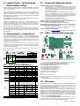
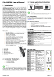
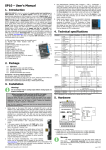
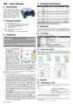
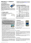
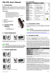
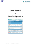
SPA7 User’s Manual
Jumpers field TA1 is for input AIn1, jumpers field TA2 is for input AIn2. SPA7 box
has to be opened before jumper settings changing (see chapter SPA7 box opening).
General signals 0 ... +10 V or 0 ... 20 mA can be recalculated to users units, e. g.
input current 4 ... 20 mA may be displayed and send in SMS like a
pressure 0 ... 5 MPa.
1. Introduction
SPA7 is a device for remote monitoring and control via GSM network. SPA7 enables
to watch 8 logical and 2 analog inputs and remote control of 4 logical outputs (state
change or pulse). SPA7 can react on it’s inputs changes by sending an SMS or by a
voice call. Names of inputs an outputs, their function, phone numbers, password
and so on are fully configurable by a PC, USB cable or remotely using GSM data
connection using program SPInit. This configuration program called SPInit is on CD
which is part of delivery. It’s also possible to download program SPInit from the
site www.seapraha.cz (English pages -> Support -> GSM-SPA7).
1)
2)
3)
4)
9
5
8
7
6
14
1
5)
2
6)
7)
8)
9)
10)
11)
12)
13)
14)
3
1
13
12
4
Indication LED
Press yellow point to eject SIM card
SIM card holder
USB connector for PC connection for
configuration and monitoring from SPInit
program
Connector for GSM antenna ANT05S which is a
part of the package
Logical Inputs Connector (DIn5 ... 8)
Logical Inputs Connector (DIn1 ... 4)
Power Watch Connector (PWW)
Power Supply Connector (PWR) (8 ... 30VDC)
RESET Pushbutton
Analog Input (AIn1) *)
Analog Input (AIn2) *)
Logical Outputs (DOut1 ... 4)
DIN-Rail Easy Mount Holder
11
*) Temperature sensor for analog input has to be
ordered separately. Available types are GSM-C-T1
and GSM-C-T2.
10
Warning
When changing jumper settings it’s highly important to make the same change in
configuration program SPInit, otherwise SPA7 will not work correctly.
Value
Range/sensor
Jumpers
Voltage
0 ... +10 V
Current
0 ... 20 mA
Temperature
KTY 81-210 (-50°C ... +150°C)
Temperature
Ni 5000 (-50°C ... +150°C)
* bi-polarity logical input
galvanically isolated
Active when voltage > 8 V
* Analog inputs acts for this setting as a standard isolated logical input: voltage
0 ... 4 V is log. 0, voltage 8 ... 30 V is logical 1. Any voltage polarity – isolated
bipolar input.
2.3 Analog Inputs Factory Setting
Input
Name
Resolution
Input
AIn1
12 bits
Temperature
sensor
AIn2
12 bits
Voltage
Factory Setting
Temperature
KTY 81-210
0 ... +10 V
Jumpers
2.4 Front Panel
SPA7 front panel contains indication LED diodes, SIM card holder and USB connector
for PC connection.
Front pannel
2. Hardware
LED
ST
green
G
yellow
R
S
P/E
yellow
yellow
green/
red
yellow
yellow
green
A
B
C
COLOR
MEANING
SPA7 status
Normally one short blink.
GSM network status
blink 1:1 … SPA7 starting up
dim … SPA7 starting up
blink shortly 1 per 3 seconds … SPA7 is fully
operational in GSM network
Receiving SMS or incoming data connection
Sending SMS or outgoing voice call
Run / Error. Green, if everything is OK. Red if
any error occurred.
For future use
For future use
CONNECTED – any data connection GPRS,
data, ...
3. Functional Test
Warning
u
It’s highly recommended to use galvanically separated power supply for
input and output external circuitry. Don’t use SPA7 power (PWR).
2.1 DIn - Logical inputs, DOut - logical outputs
u
+
+
Logical inputs (SPA7 input signals) are connected to DIn1-4 and DIn5-8 connectors.
Logical outputs (SPA7 output signals) are connected to Dout1-4 connector. Internal
SPA7 circuitry and recommended external circuitry:
u
u
u
u
PWW (Power Watch) input can be used as 9th logical input if not used for power
watch.
u
2.2 AIn - Analog Inputs:
Voltage/Current/Temperature selection
u
SPA7 has 2 analog inputs - connectors AIn1 and AIn2. Measured variable selection
can be done by jumpers. Each input has it’s own jumpers field (see pict. Hardware)
To operate SPA7 any SIM card of any GSM operator is necessary. The
SIM card has to be fully operational, with non zero credit in case of
prepaid SIM card. It’s recommended to make a test of a SIM card in a
standard mobile phone: SMS sending and receiving and incoming and
outgoing voice and data calls.
It’s recommended to deactivate PIN usage on a SIM card for the first
test of SPA7 which can be done without changes in example
configuration in SPA7. PIN usage can be deactivated in
standard mobile phone: Menu -> Settings -> Mobile
Security -> PIN
Insert SIM card into SPA7. SIM card holder is located on a
front panel of SPA7. Press a yellow point to eject a SIM
card holder.
Connect an antenna to SMA connector ANT.
Insert 2 pin connector with a temperature sensor KTY 81210 into AIn1 analog input.
Connect a power supply for SPA7 (8 ... 30 VDC) into a PWR connector. If
everything is OK the green LED ST on a front panel of SPA7 starts
blinking. When blinking twice shortly, SPA7 is starting up. After about 30
seconds begins blinking once shortly and SPA7 is ready. Notes: If a P/E
LED lights red, any problem occurred. Use your computer and USB cable
to find out the cause of a problem.
Send an SMS message from your mobile phone to a SIM card phone
number in SPA7 in form “1234 STATE”. SPA7 will send back an SMS with
inputs and outputs status depending on factory configuration of SPA7.
You will receive a status SMS will look like this: “Test SPA7:
Window=CLOSED Elevator=OK HEATING=OFF Temperature=28'C
MIDDLE SIGNAL=56%.”
4. Configuration
5. Remote Control
4.1 First Configuration and Basic Functions
Guide
5.1 SMS Message control
First of all, please, install USB driver and
program SPInit to your PC from
delivered CD. Now connect SPA7 and PC
with USB cable.
For the first test we recommend to use
“First Configuration Guide”, which is
automatically installed with program
SPInit. Configuration Guide helps you to
prepare basic configuration of SPA7 in
just few steps. It helps you to set up
important configuration items for the
first test of SPA7 (phone number, user
name, and writes modified configuration to SPA7. After quitting the Guide, program
SPInit stays running. You can use it to prepare complete configuration for practical
use and to monitor SPA7. It’s useful to test monitoring now. Press the pushbutton
[Connect] and select an item “Analog inputs” on the card called [Monitoring]. You
will see the actual temperature on the temperature sensor. Click on the item
“Logical inputs”. All of them will be in non active state. Activate an input DIn4 with
bringing voltage 8 … 30 VDC between pins C and 5 of DIn1-4 connector. Watch the
inputs state change on your PC display. Now try to activate input DIn1 (pin C and
1). You will see the change on your PC display and SMS message will follow due to
SPA7 factory configuration where the change of input DIn1 is set to send SMS
message. Similarly is possible to send
an
SMS
caused
by
increasing
temperature on sensor over 30°C. Now
try to switch on the output DOut1 by
sending SMS from your mobile phone to
phone number of a SIM card in SPA7 in
form “1234 OUTPUT1 ON”. You will see
the change of an output in the item
logical outputs. You will receive a
confirmation SMS message on your
mobile phone (supposing you didn’t use
the command “NOBACK” in the
command SMS.
Now is possible to configure SPA7 for
intended with program SPInit.
Example use of recalculation values on
analog input to users units:
E.g. Analog input is set as a current
input 0 ... 20 mA. A pressure sensor
yields 4 mA by 0 MPa and 20 mA by
10 MPa.
SPA7 is controlled via SMS messages of GSM network. Command SMS messages are
in form:
<PASSWORD> <COMMAND> [<RETURN COMMAND >]
Example:
1234 STATE
… SPA7 returns an SMS containing status
1234 DOUT1 ON
… SPA7 output1 will be switched on. Confirmation SMS will
be returned
1234 DOUT8 PULSE NOBACK … SPA7 pulse on output8 will be generated, no
confirmation message will be send
It’s possible to write more commands into one command SMS. For higher readability
separate commands by semicolon “;” inside command use “=”.
1234 OUTPUT0=ON; OUTPUT1=ON; OUTPUT3=PULSE;
Names of inputs and outputs are user definable by SPInit program. Command SMS
may look like this:
1234 GATE=OPEN; HEATING=ON; LAMP=BLINK
5.2 Status SMS Text Message
Whenever command SMS contains valid password, SPA7 always returns status SMS.
Status SMS contains following information:
<Device Name>: <LogInput1>=<LogInput1Status> <LogInput2>=<LogInput2Stat
us> ...
<LogOutput1>=<LogOutput1Status>
<LogOutput2>=<LogOutput1Status> ... <GSM Signal Level>
Status SMS message contains information only about selected inputs and outputs.
Selection is done in configuration program SPInit by checking the appropriate
checkbox.
SPA7 Status SMS
Example
Device SPA7:
DIn1=on
DIn2=off
DOut3=on
Signal=58%
Explanation
Device Name (user configurable)
Logical Input 1 is on
Logical Input 2 is off
Logical Output 3 is on (closed)
GSM Signal level in %
6. Monitoring
Program SPInit enables to watch status of inputs and outputs on PC monitor in tab
“Monitoring”. Monitoring can be local via USB cable or remote via GSM data
connection. It’s possible to switch on or off logical outputs by clicking on pushbutton
[Change] or [Pulse]. It helps to check function of external circuitry.
The proper SPInit parameter settings
are on the picture.
4.2 SPInit - Important Terms Explanation
PIN (Personal Identification Number – usually four digits number). Only persons
with knowledge of PIN can operate a SIM card (in case the PIN usage on a SIM card
was activated). Usage of the PIN can be deactivated. Insert the SIM card to your
mobile phone and follow the instruction in the mobile phone manual. (Usually the
PIN usage can be deactivated in Menu -> Security -> PIN).
ACCESS CODE = Password for SMS commands, configuration and monitoring of
SPA7. SPA7 accepts only SMS with a valid access code. The password is requested
also for connection of SPA7 with PC (via USB cable or remotely via data connection
of GSM network). Factory setting of access code is “1234”.
EVENT = level change in case of logical input, zone change in case of analog
inputs. SPA7 can reacts on EVENTS by several ACTIONS if was setup this way.
SPA7 can send SMS messages on selected phone numbers and to make voice calls
on selected phone numbers.
ACTION = one voice call or one SMS to one user. Any EVENT can contain several
ACTIONS.
USER LIST = List of all users and their phone numbers which are used for
ACTIONS. User names are used only for better clarity. SPA7 does not use them in
any way.
4.3 Remote Configuration
SPA7 can be configured remotely via GSM data
connection in the same way like via USB cable.
Just click in menu [Options] and in new window
called “Options” set the “Station’s phone”
number for data connection to SPA7. Click [OK]
to close the window.
7. Events
SPA7 can be set up to inform about events (= changes) on its logical and analog
inputs. SPA7 sends information via SMS message or makes a voice call. By the
SPInit program is possible to set several actions for each event specifying the phone
number – user who will receive an SMS message and who will be called. A various
SMS can be sent to and a voice call can be make to more phone numbers from the
list. The order of SMS and voice calls depends on a list of actions for each action.
Voice call rises the probability the user will not miss received SMS message.
First of all the Event has to be created in the configuration program SPInit. Click by
a mouse on the symbol of a key
. By a pushbutton [+ ADD] select requested
action of SPA7 (SMS or voice call), write the text of SMS which has to be sent or
insert the sequence of DTMF numbers in case of a voice call. Now select a user and
add him to a list of users for this event by a click on an arrow [>>]. Please check
carefully the number of users for an event. If case the number of users is zero
nothing will happen.
8. Logical Inputs – Special Usage:
Event number coding
“Events number coding” can activate more events than is the number of inputs. For
this special function is possible to select several SPA7’s input signals. (See. program
SPInit – card “Advanced”)
Typical usage is when the error numbers are sent as a code. This decreases the
number of signals needed for communication with e. g. PLC. The signals with a code
are called “data” signals. When these signals are valid, they are strobe by a signal
called “data valid”. On a rising edge of this signal, the “data signals” are evaluated
and adequate event is generated.
Any combination of input “data” signal is an independent event which can send
SMS and make a voice call (see chap. Inputs Events)
Example: If a combination of four inputs 1 1 0 1: means a serious failure it’s
possible to send following SMS “A serious failure in the city steam plant.” to all
technical stuff and to the head of the firm too. And then to make a voice call to all
technicians to increase probability they will read the SMS. (See. The Advanced
example configuration in the SPInit program).
The input signals for this function are selected beginning by input no 1. All other not
used inputs keeps their former function. All 8 (7 data + 1 strobe) logical inputs of
SPA7 is possible to use for this special function. It means up to 128 (2^7) events
can be assigned.
11. Frequently Asked Questions
1. What is necessary to use SPA7 successfully?
u
SIM card capable to send and receive SMS messages from standard
mobile phone and voice / data call incoming and outgoing as well.
Please test all these functions in your mobile phone. It’s important to
solve all possible problems before using SIM card in SPA7. Contact your
mobile operator if necessary.
u
Good quality GSM signal in area of installation of SPA7 (at least 2 or 3
bars on your mobile phone). If there is a problem with GSM signal
quality, try to use another type of external antenna, which can be placed
in proper place with better GSM signal and which is connected to SPA7
with several meters long coax cable with SMA connector.
u
Sufficient Credit (in case of prepaid SIM card)
u
Cancel all phone calls redirection for a SIM card in SPA7
2. What is a phone number of SCA (SCA = Service Center Address) of my
mobile operator? (It’s not possible to send an SMS)
u
Contact your mobile operator for this piece of information.
3. I wanted to test SPA7 with my own SIM card. Now I cannot find SMS
messages formerly stored on my SIM card.
u
SMS from your SIM card were processed by SPA7 and then deleted.
They were very probably canceled due to syntactical error.
4. Where can I find more information?
u
See the website www.seapraha.cz (English pages->Support->GSM-SP6).
12. SPA7 / SPA7EXP Box Opening
9. Analog Inputs – Comparators
Full range of A/D converter can be split into 2 or more zones (pushbutton [+] on a
card Zones and Events) which can be named e. g. LOW, OK, HIGH, EMERGENCY.
Now add the zone names set the border values and the hysteresis. select
[Transition] for this. The border is set in user units (the same units as in SMS). Now
is possible to create events for transition of analog value between these zones (in
the same way like for logical inputs).
Analog input range can be separated into several zones. The names of these zones
are used in SMS. When the input value goes over the zone border is caused an
event in SPA7 and a prepared SMS is sent or a voice call on preset phone numbers
is made. (see chap. Input Events).
Input value depends on analog input mode configuration. Voltage / current /
temperature are available.
To open SPA7 / SPA7EXP box for changing the jumper settings follow these steps:
10. Technical specifications
Parameter
Dimensions
Power
supply
Logical
inputs DC
any polarity
Logical
outputs DC,
AC
Analog
inputs
A1 a A2
Temperature
Width
Height (without
antenna)
Depth
Voltage DC
Current
Count
Voltage log. H
Voltage log. L
Current
Count
Voltage
Current
Count
Measured values
Voltage
measuring
Input resistance
Current
measuring
Input resistance
Temperature
measuring 1
Temperature
measuring 2
Logical input
Resolution
Operational
Symbol
w
h
d
VCC
ICC
|VIN|
|VIN|
IIN
VOUT
IOUT
-
-
Conditions
MIN.
VCC = 12V
8
0,1
MAX. Unit
mm
mm
120
8
VIN = 12V
30
0,4
8
12
<4
5
4
30
4
50
100
2
voltage, current, temperature *), logical input
(user selectable)
Temperature value is not valid before the
temperature condition is stable
0
10
RIN
-
voltage
RIN
sensor
current
18
0
20
mm
V DC
A
V
V
mA
V
mA
-
V
kΩ
mA
Ω
100
KTY 81-210
sensor
See
tA
TYP.
22
100
Ni 5000
logical
inputs
12
-20
SPA7 is designed to be used inside a building only!
+65
bits
°C
1 - Free the red (dark) DIN-Rail holder: rise up the holder gently to free small key
(1a), from a slot (1b) which keeps the holder in working position.
Please mind the small spring (1c), located behind the holder!
2 - Free the holding hook using screwdriver
3 - Free the holding hook using screwdriver
4 - Gently draw apart the back side of a SPA7 box
5 - Free the holding hook using screwdriver
6 - Free the holding hook using screwdriver
7 - Gently free the whole side board of SPA7
Use similar steps in case of SPA7EXP.
Notes:
A – The hole for a holding hook
B – One of four small keys holding PCB of SPA7 to a side board (no screws for
mounting are used)
C – The spindle fitting the hole on the opposite part of a box holds the box together.
13. Warranty
General warranty period is 12 months after purchase, when eventual malfunction
device will be repaired free of charge in SEA company while shipping to SEA is paid
by customer and SEA pays for shipping back to customer. For SW there is 24
months warranty under following conditions:
Both CPU and PC software is sold “as is”. The software was created by the best
software engineers in SEA and was carefully tested both in SEA and also by SEA
customers using GSM applications products made in SEA. In spite of making all
possible to get error free software it can happen, that the software in CPU or PC
programming SW or their mutual interaction has some error under some specific
conditions. If such error is found and the description of the problem including
configuration file is sent by E-mail to SEA ltd., the error is removed free of charge
and SEA will send new SW by E-mail to customer.
SEA ltd. has NO RESPONSIBILITY for any damage, lost, costs and
any other problems direct or inducted, caused by such SW error, by eventual device
malfunction from any reason or by undelivered SMS from the device.
(Version 1.15; 2007-08-10)