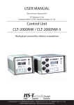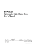
1
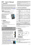
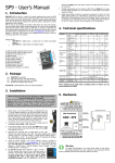
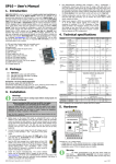
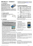
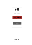
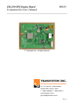
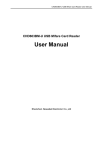
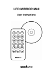
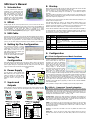
SP6 User’s Manual 8. Startup 1. Introduction Before startup, place the SIM card into the SIM card reader and connect the GSM antenna. Then connect the power supply to connector JP6. LED STA /status/ on the right starts flashing with 2 short subsequent flashes (●● ●●). When flashing changes to 1 short flash (● ●) the device is ready for operation. Now, send a SMS text message from your mobile in the form “1234 STATE” to the telephone device number SP6. The device will respond with a message describing its status “SP6: Input1=Off, Input2=Off, …” You have purchased the device for monitoring of 8+1 logical inputs and remote control of 8 log. outputs using SMS text messages. The device is highly versatile and must be configured with a PC using SpInit software supplied on CD. The program requires Windows 98 or higher (recommended Windows 2000 or Windows XP). If the status of any input is changed, the device sends a SMS text message to your mobile in the form “Input1 is On”. 2. SPInit Install program SP Init from the provided CD into your PC. Insert CD into the PC drive and wait till the introductory screen pops up. In the menu, select installation of program SP Init and follow the wizard instructions. Then on the introductory screen select installation of USB driver and install it. (Typically to a folder “C:\Cygnal\CP2101”). The program SPInit can be also downloaded free of charge from the website www.seapraha.cz (English pages Ö Support Ö GSM-SP6). 3. USB Cable Interconnect your PC with the device using the USB cable supplied with the delivery. After the first connection, the computer prompts you to install the USB port drivers. Files of this driver were installed into your PC during step 1 and typically can be found in folder “C:\Cygnal\CP2101”. The driver creates a new virtual serial port on your PC, you can check clicking Control panels, System, Hardware, Device Manager. 4. Setting Up The Configuration Green COLOR GSM Green MEANING SP6 status Normally one short blink. GSM network status blink 1:1 … SP6 starting up blink shortly 1 per 3 seconds … SP6 is fully operational in GMS Yellow Yellow Red network Sending SMS or outgoing voice call Receiving SMS or incoming data connection Error. Use the program SPInit or service module SM2 to find the problem. 9.1 First Configuration and Basic Functions Click button [Save] in the bottom part of the screen. Allow a while for the program to locate the device and wait until the configuration is saved. The SP6 device is power supplied during the configuration from the USB port and the main power supply unit needs not be connected. Now disconnect USB cable. POWER USB JP6 JP7 USB JP8 J7 SIM Card Holder SP6 J4 J2 J5 J6 PWR WATCH JP5 GSM STA ERR RCV SND J3 DIn 7. Inputs and Outputs LED STA 9. Configuration 5. Saving The Configuration The SP6 device is power supplied from 8 V ... 30 V DC power supply unit. This voltage is supplied to connector JP6 in the upper left part of the device. The polarity is shown in the figure on the right. Yellow LED RCV indicates a SMS text message is received and yellows LED SND on the right hand side of the device indicates a SMS text message is sent. Connector JP1 is designed to connect service module SM2 that displays status details of the device and can be used to run detail diagnostics. SND RCV ERR Start program SP Init (Start Ö Programs Ö SEA Ö SP Init Ö SP Init x.x.x). Read configuration from device by clicking button [Read] in bottom left corner of main window. Enter correct PIN for your SIM card (panel General). On tab User List enter your phone number to and your name instead of user Smith. 6. Power Supply Red LED ERR changing its status to On during startup indicates that an error occurred. Check that PIN was specified correctly in the SP Init configuration program and that the antenna is connected. For more information see the User Manual to device SP6, chapter Function – Errors During Startup Sequence. DOut LOGICAL PRG SM2 INPUTS KAB JP3 JP2 JP1 LOGICAL OUTPUTS You can use program SPInit to prepare complete configuration for practical use and to monitor SP6. It’s useful to test monitoring now. Press the pushbutton [Connect] and select an item “Logical inputs”. All of them will be in non active state. Activate an input DIn4 with bringing voltage 8 … 30 VDC between pins C and 5 of DIn1-4 connector. Watch the inputs state change on your PC display. Now try to activate input DIn1 (pin C and 1). You will see the change on your PC display and SMS message will follow due to SP6 factory configuration where the change of input DIn1 is set to send SMS message. Similarly is possible to send a SMS caused by increasing temperature on sensor over 30°C. Now try to switch on the output DOut1 by sending SMS from your mobile phone to phone number of a SIM card in SP6 in form “1234 OUTPUT1 ON”. You will see the change of an output in the item logical outputs. You will receive a confirmation SMS message on your mobile phone (supposing you didn’t use the command “NOBACK” in the command SMS). Now is possible to configure SP6 for intended purpose with the program SPInit. JP4 Inputs (signals to SP6) are supplied to connector JP3 and outputs (signals from SP6) are connected to connector JP4. See the diagrams below for connection of these signals. 9.2 SPInit - Important Terms Explanation PIN (Personal Identification Number – usually four digits number) Only persons with knowledge of PIN can operate a SIM card (in case the PIN usage on a SIM card was activated). Usage of the PIN can be deactivated. Insert the SIM card to your mobile phone and follow the instruction in the mobile phone manual. (Usually the PIN usage can be deactivated in Menu -> Security -> PIN ACCESS CODE – Password for SMS commands, configuration and monitoring of SP6. SP6 accepts only SMS with a valid access code. The password is requested also for connection of SP6 with PC (via USB cable or remotely via data connection of GSM network). Factory setting of access code is „1234“. EVENT = level change in case of logical input, zone change in case of analog inputs. SP6 can reacts on EVENTS by several ACTIONS if was setup this way. SP6 can send SMS messages on selected phone numbers and to make voice calls on selected phone numbers. ACTION = one voice call or one SMS to one user. Any EVENT can contain several ACTIONS. USER LIST = List of all users and their phone numbers which are used for ACTIONS. User names are used only for better clarity. SP6 does not use them any way. 9.3 Remote Configuration SP6 can be configured remotely via GSM data connection in the same way like via USB cable. Just click in menu [Options] and in new window call Options set the phone number for data connection to SP6. 10. Remote Control 10.1 SMS Message control SP6 is controlled via SMS messages of GSM network. Command SMS messages are in form: <PASSWORD> <COMMAND> [<RETURN COMMAND >] Example: 1234 STATE … SP6 returns a SMS containing status 1234 DOUT1 ON … SP6 output1 will be switched on. Confirmation SMS will be returned 1234 DOUT8 PULSE NOBACK … SP6 pulse on output8 will be generated. No confirmation message will be send It’s possible to write more commands into one command SMS. For higher readability separate commands by semicolon “;” inside command use “=”. 1234 OUTPUT0=ON; OUTPUT1=ON; OUTPUT3=PULSE; Names of inputs and outputs are user definable by SPInit program. Command SMS may look like this: 1234 GATE=OPEN; HEATING=ON; LAMP=BLINK 10.2 SP6 Status SMS Message Whenever command SMS contains valid password, SP6 always returns status SMS. Status SMS contains following information: <Device Name>: <LogInput1>=<LogInput1Status> <LogInput2>=<LogInput2Stat us> ... <LogOutput1>=<LogOutput1Status> <LogOutput2>=<LogOutput1Status> ... <GSM Signal Level> Status SMS message contains information only about selected inputs and outputs. Selection is done in configuration program SPInit by checking the appropriate checkbox. SP6 Status SMS Example Device SP6: DIn1=on DIn2=off DOut3=on Signal=58% Explanation Device Name (user configurable) Logical Input 1 is on Logical Input 2 is off Logical Output 3 is on (closed) GSM Signal level in % 11. Monitoring Program SPInit enables to watch status of inputs and outputs on PC monitor in tab “Monitoring”. Monitoring can be local via USB cable or remote via GSM data connection. It’s possible to switch on or off logical outputs by clicking on pushbutton [Change] or [Pulse]. It helps to check function of external circuitry. 12. Inputs Events SP6 can be set up to inform about events (=changes) on its logical and analog inputs. SP6 sends information via SMS message or makes a voice call. By the SPInit program is possible to set several actions for each event specifying the phone number – user who will receive a SMS message and who will be called. A various SMS can be sent to and a voice call can be make to more phone numbers from the list. The order of SMS and voice calls depends on a list of actions for each action. Voice call rises the probability the user will not miss received SMS message. First of all the Event has to be created in the configuration program SPInit. Click by a mouse on the symbol of a key . By pushbutton [+ ADD] select requested action of SP6 (SMS or voice call), write the text of SMS which has to be sent or insert the sequence of DTMF numbers in case of a voice call. Now select a user and add him to a list of users for this event by a click on an arrow [>>]. Please check carefully the number of users for an event. If case the number of users is zero nothing will happen / no SMS will be send /. 13. Logical Inputs – Special Usage: Event number coding “Events number coding” can activate more events than is the number of inputs. For this special function is possible to select several SP6’s input signals. (See. program SPInit – card “Advanced”) Typical usage is when the error numbers are sent as a code. This decreases the number of signals needed for communication with e. g. PLC. The signals with a code are called “data” signals. When these signals are valid, they are strobe by a signal called “data valid”. On a rising edge of this signal, the “data signals” are evaluated and adequate event is generated. Any combination of input “data” signal is an independent event which can send SMS and make a voice call (see chap. Inputs Events) Example: If a combination of four inputs 1 1 0 1: means a serious failure it’s possible to send following SMS “A serious failure in the city steam plant.” to all technical stuff and to the head of the firm too. And then to make a voice call to all technicians to increase probability they will read the SMS. (See. The Advanced example configuration in the SPInit program). The input signals for this function are selected beginning by input no 1. All other not used inputs keeps their former function. All 8 (7 data + 1 strobe) logical inputs of SP6 is possible to use for this special function. It means up to 128 (2^7) events can be assigned. 14. Technical specifications Parameter Dimensions Power supply Logical inputs DC any polarity Logical outputs DC, AC Temperature Symbol Width Height (without antenna) Depth Voltage DC w h Current Count Voltage log. H Voltage log. L Current Count Voltage Current Operational ICC |VIN| Conditions MIN. MAX. 22 100 d VCC VCC = 12V 8+1 12 30 mm V DC A V <4 4 V 30 0,1 8 VIN = 12V Unit mm mm 120 8 |VIN| IIN VOUT IOUT tA TYP. 0,4 5 8 -20 50 100 +65 mA V mA °C SP6 is designed to be used inside a building only! 15. Frequently Asked Questions 1. What is necessary to use SP6 successfully? SIM card capable to send and receive SMS messages from standard mobile phone and voice / data call incoming and outgoing as well. Please test all these functions in your mobile phone. It’s important to solve all possible problems before using SIM card in SP6. Contact your mobile operator if necessary. Good quality GSM signal in area of installation of SP6 (at least 2 or 3 bars on your mobile phone). If there is a problem with GSM signal quality, try to use another type of external antenna, which can be placed in proper place with better GSM signal and which is connected to SP6 with several meters long coax cable with SMA connector. Sufficient Credit (in case of prepaid SIM card) Cancel all phone calls redirection for a SIM card in SP6 2. What is a phone number of SCA (SCA = Service Center Address) of my mobile operator? (You might deal with this, when it’s not possible to send SMS form your SIM card….) Contact your mobile operator for this information. 3. I tested SP6 with my own SIM card. Now I cannot find SMS messages formerly stored on my SIM card. SMS from your SIM card were processed by SP6 and then deleted. In SP6 any received SMS is deleted just after being analyzed and executed 4. Where can I find more information? See the website www.seapraha.cz (English pages->Support->GSM-SP6). 16. Warranty General warranty period is 12 months after purchase, when eventual malfunction device will be repaired free of charge in SEA company while shipping to SEA is paid by customer and SEA pays for shipping back to customer. For SW there is 24 months warranty under following conditions: Both CPU and PC software is sold “as is”. The software was created by the best software engineers in SEA and was carefully tested both in SEA and also by SEA customers using GSM applications products made in SEA. In spite of making all possible to get error free software it can happen, that the software in CPU or PC programming SW or their mutual interaction has some error under some specific conditions. If such error is found and the description of the problem including configuration file is sent by E-mail to SEA ltd., the error is removed free of charge and SEA will send new SW by E-mail to customer. SEA ltd. has NO RESPONSIBILITY for any damage, lost, costs and any other problems direct or inducted, caused by such SW error, by eventual device malfunction from any reason or by undelivered SMS from the device. (Version 1.13; 2006-11-28)